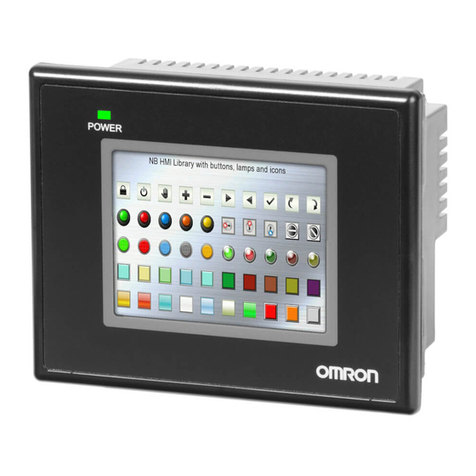
Bernecker + Rainer MP181 User manual

1Mobile Panel User's Manual V 1.5
Mobile Panel
User's Manual
Version: 1.5 (Jan. 2005)
Model No.: 5MAMPX.0001-EN
We reserve the right to change the contents of this manual without warning. The information
contained herein is believed to be accurate as of the date of publication; however, Bernecker +
Rainer Industrie-Elektronik Ges.m.b.H. makes no warranty, expressed or implied, with regards
to the products or the documentation contained within this book. In addition, Bernecker + Rainer
Industrie-Elektronik Ges.m.b.H. shall not be liable in the event of incidental or consequential
damages in connection with or resulting from the furnishing, performance, or use of these
products. The software names, hardware names, and trademarks contained in this document are
registered by the respective companies.
5MAMPX.0001-DE

2 Mobile Panel User's Manual V 1.5

3Mobile Panel User's Manual V 1.5
Chapter 1: General information
Chapter 2: Technical Data
Chapter 3: Start-up / Operation
Chapter 4: Software
Chapter 5: Standards and Certifications
Chapter 6: Accessories

4 Mobile Panel User's Manual V 1.5

5Mobile Panel User's Manual V 1.5
Chapter 7: Maintenance / Servicing
Appendix A: Data
Figure Index
Index
Table Index
Model Number Index

6 Mobile Panel User's Manual V 1.5

7Mobile Panel User's Manual V 1.5
Table of Contents
Chapter 1: General Information ..................................................... 11
1. Manual History .................................................................................................................... 11
2. Safety Notices ..................................................................................................................... 13
3. Guidelines ........................................................................................................................... 13
4. Safety Regulations .............................................................................................................. 13
4.1 Introduction .................................................................................................................... 13
4.2 Intended Use ................................................................................................................. 14
4.3 Transport and Storage .................................................................................................. 14
4.4 Mounting ........................................................................................................................ 14
4.5 Operation ....................................................................................................................... 15
4.5.1 Supply Voltage ........................................................................................................ 15
4.5.2 E-stop System ......................................................................................................... 16
4.5.3 Enable Switch ......................................................................................................... 16
5. Model Numbers .................................................................................................................. 18
5.1 Operating Unit ............................................................................................................... 18
5.2 Handle ........................................................................................................................... 18
5.3 Connection Cable .......................................................................................................... 18
5.4 Switching Cabinet Cable ............................................................................................... 19
5.5 Wall Mount .................................................................................................................... 19
5.6 Strapping Plug ............................................................................................................... 19
5.7 Accessories ................................................................................................................... 20
5.8 Software ........................................................................................................................ 20
Chapter 2: Technical Data .............................................................. 21
1. Introduction ......................................................................................................................... 21
1.1 Features ........................................................................................................................ 22
1.2 Construction .................................................................................................................. 23
2. Entire Device ...................................................................................................................... 24
2.1 Dimensions .................................................................................................................... 24
2.2 Technical Data .............................................................................................................. 25
3. Individual Components ....................................................................................................... 27
3.1 Operating Unit ............................................................................................................... 27
3.1.1 Dimensions ............................................................................................................. 28
3.1.2 Mylar Keypad .......................................................................................................... 28
3.1.3 Entry Devices .......................................................................................................... 29
3.1.4 Touch Screen Pen .................................................................................................. 30
3.1.5 CF / USB Cover ..................................................................................................... 30
3.1.6 Rear View of an Operating Unit .............................................................................. 35
3.1.7 Switches, Buttons and Batteries ............................................................................. 36
3.1.8 Technical Data ........................................................................................................ 39
3.2 Handle ........................................................................................................................... 59
3.2.1 Dimensions ............................................................................................................. 60
3.2.2 Technical Data ........................................................................................................ 60
3.2.3 Enable Switch ......................................................................................................... 60
3.2.4 Operating Unit Fastener .......................................................................................... 62
3.2.5 Fastening the Connection Cable ............................................................................. 63
Table of Contents

8 Mobile Panel User's Manual V 1.5
Table of Contents
3.3 Connection Cable ..................................................................................................... 64
3.3.1 Technical Data ........................................................................................................ 65
3.3.2 Cable Specifications ............................................................................................... 66
3.4 Switching Cabinet Cable Crossover .............................................................................. 68
3.4.1 Shielding in the Switching Cabinet .......................................................................... 68
3.4.2 Technical Data ........................................................................................................ 69
3.4.3 Cable Specifications ............................................................................................... 70
3.4.4 Drilling Template for the Connection Housing ........................................................ 71
3.5 Switching Cabinet Cable - Straight Through ................................................................. 73
3.5.1 Shielding in the Switching Cabinet .......................................................................... 73
3.5.2 Technical Data ........................................................................................................ 74
3.5.3 Cable Specifications ............................................................................................... 75
3.5.4 Drilling Template for the Connection Housing ........................................................ 76
3.6 Wall Mount .................................................................................................................... 77
3.6.1 Technical Data ........................................................................................................ 78
3.6.2 Dimensions ............................................................................................................. 79
3.6.3 Storing the Mobile Panel Device ............................................................................. 80
3.7 Strapping Plug ............................................................................................................... 81
3.7.1 Order Data .............................................................................................................. 81
3.7.2 Technical Data ........................................................................................................ 81
3.7.3 Cable Layout ........................................................................................................... 82
Chapter 3: Start-up / Operation ..................................................... 83
1. Commissioning from a Safety Point of View ....................................................................... 83
1.1 Intended Use ................................................................................................................. 83
2. Operating the Mobile Panel Device .................................................................................... 84
3. Recommended Monitoring Devices .................................................................................... 85
3.1 Connection Examples for the E-stop and Key Switch ................................................... 86
3.1.1 Connection Example for Safety Circuits up to EN 954-1 Category 4 ...................... 86
3.1.2 Connection Example for Safety Circuits up to EN 954-1 Category 1 ...................... 88
3.2 Connection Example for the Enable Switch .................................................................. 90
3.2.1 Connection Example for Safety Circuits up to EN 954-1 Category 4 ...................... 90
3.3 Current Load of the Enable Switch and Entry Device Circuit ........................................ 92
Chapter 4: Software ........................................................................ 93
1. Mobile Panel with Automation Runtime .............................................................................. 93
1.1 General Information ....................................................................................................... 93
1.2 Control and Visualization with the Mobile Panel ........................................................... 94
1.3 Operation and Monitoring with the Mobile Panel ........................................................... 95
1.4 Summary Screen ........................................................................................................... 95
2. Mobile Panel with Windows CE .......................................................................................... 97
2.1 General Information .................................................................................................... 97
2.2 Requirements ................................................................................................................ 97
2.3 Installation ..................................................................................................................... 97
2.4 Serial ActiveSync Connection ....................................................................................... 98
2.5 Mobile Panel as a Thin Client ........................................................................................ 99

9Mobile Panel User's Manual V 1.5
Table of Contents
3. Mobile Panel with Windows XP Embedded ...................................................................... 100
3.1 General Information .................................................................................................... 100
3.2 Requirements .............................................................................................................. 100
3.3 Installation Procedures ................................................................................................ 100
Chapter 5: Standards and Certifications .................................... 101
1. Valid European Guidelines ............................................................................................... 101
2. Overview of Standards ..................................................................................................... 101
3. Requirements for Emissions (Emission) ........................................................................... 103
3.1 Network Related Emissions ........................................................................................ 103
3.2 Electromagnetic Emissions ......................................................................................... 104
4. Requirements for Immunity to Disturbances (Immunity) ................................................... 105
4.1 Electrostatic Discharge (ESD) ..................................................................................... 106
4.2 High-frequency Electromagnetic Fields (HF field) ....................................................... 106
4.3 High-speed Transient Electrical Disturbances (Burst) ................................................. 107
4.4 Surge Voltages (Surge) ............................................................................................... 107
4.5 Conducted Disturbances ............................................................................................. 107
4.6 Magnetic fields with energy technical frequencies ...................................................... 108
4.7 Voltage dips, fluctuations and short-term interruptions ............................................... 108
4.8 Damped Oscillations ................................................................................................... 109
5. Mechanical Conditions ...................................................................................................... 110
5.1 Vibration Operation ..................................................................................................... 110
5.2 Vibration Transport ...................................................................................................... 110
5.3 Shock Operation .......................................................................................................... 111
5.4 Shock Transport (packed) ........................................................................................... 111
5.5 Toppling ....................................................................................................................... 111
5.6 Free Fall (packed) ....................................................................................................... 112
6. Climate Conditions ............................................................................................................ 112
6.1 Worst Case Operation ................................................................................................. 113
6.2 Dry Heat ...................................................................................................................... 113
6.3 Dry Cold ...................................................................................................................... 113
6.4 Large Temperature Fluctuations ................................................................................. 113
6.5 Temperature Fluctuations in Operation ....................................................................... 114
6.6 Humid Heat, Cyclical ................................................................................................... 114
6.7 Humid Heat, Constant (storage) .................................................................................. 114
7. Further Limit Values .......................................................................................................... 114
8. International Certifications ................................................................................................ 116
8.1 BGFE Certificate ......................................................................................................... 116
9. Standards and Definitions for Safety Technology ............................................................. 117
Chapter 6: Accessories ................................................................ 121
1. Overview ........................................................................................................................... 121
2. Replacement CMOS Batteries .......................................................................................... 122
2.1 Order Data ................................................................................................................... 122
2.2 Technical Data ............................................................................................................ 122
3. Touch Screen Pen ............................................................................................................ 123

10 Mobile Panel User's Manual V 1.5
Table of Contents
3.1 Order Data ................................................................................................................... 123
4. Compact Flash cards 5CFCRD.xxxx-02 ........................................................................... 124
4.1 General Information ..................................................................................................... 124
4.2 Order Data ................................................................................................................... 124
4.3 Technical Data ............................................................................................................ 124
4.4 Dimensions .................................................................................................................. 125
4.5 Calculating the Lifespan .............................................................................................. 126
5. USB Memory Stick ............................................................................................................ 132
5.1 General Information ..................................................................................................... 132
5.2 Order Data ................................................................................................................... 132
5.3 Technical Data ............................................................................................................ 132
Chapter 7: Maintenance / Servicing ............................................ 135
1. Cleaning ............................................................................................................................ 135
2. Exchanging the Connection Cable ................................................................................... 136
2.1 Procedure .................................................................................................................... 136
3. Changing the Battery ........................................................................................................ 141
3.1 Procedure .................................................................................................................... 141
Appendix A: .................................................................................. 145
1. E-stop button .................................................................................................................... 145
2. Key Switch ........................................................................................................................ 146
3. Enable Switch ................................................................................................................... 147
4. Touch Screen ................................................................................................................... 148
4.1 3M Touch .................................................................................................................... 148
4.1.1 Cleaning ................................................................................................................ 149
4.2 Gunze Touch ............................................................................................................... 149
4.2.1 Cleaning ................................................................................................................ 150
5. Mylar ................................................................................................................................. 150
6. Filter Glass ........................................................................................................................ 152
6.1 Mechanical Characteristics ......................................................................................... 152
6.2 Chemical Properties .................................................................................................... 152
7. Housing ............................................................................................................................. 152

General Information • Manual History
Chapter 1
General Information
11Mobile Panel User's Manual V 1.5
Chapter 1 • General Information
1. Manual History
Information:
B&R does its best to keep the printed versions of its user's manuals as current as
possible. However, sometimes a newer version of the user's manual can be
downloaded in electronic form (pdf) from the B&R homepage www.br-
automation.com.
Version Date Comment
1.0 16.03.2004 First edition, created with BuR HB manual template V33_09_2003
1.1 17.09.2004 Changes / New Features
- New image for "Automation Runtime summary screen", on page 96 and corresponding
description in the table "Automation Runtime summary screen", on page 96.
- New image for "Wall Mount 4MPBRA.0000-00", on page 77.
- Section for wall mount installation of the Mobile Panel using 4MPBRA.0000-00 added (see section
"Storing the Mobile Panel Device", on page 80).
- Replacement touch screen pen added, see section "Touch Screen Pen", on page 123.
- Section "Recommended Monitoring Devices", on page 85 updated - Note regarding unwanted
safety category 4 according to EN 954-1 was added.
- Section "Switching Cabinet Cable - Straight Through", on page 73 (5CAMPC.0020-01) added.
- Chapter 5 "Standards and Certifications" updated.
- Safety-related texts matched to the current BGFE guidelines.
- Section "Current Load of the Enable Switch and Entry Device Circuit", on page 92 added.
- Section "Features", on page 22 for Mobile Panel devices updated.
- Section "Entire Device", on page 24 updated.
- Figure "Dimensions for the entire device", on page 24 added.
- "Appendix A" updated.
- Section "Compact Flash cards 5CFCRD.xxxx-02", on page 124 updated.
- Technical data for all operator panels was expanded.
Table 1: Manual history

12
General Information • Manual History
Mobile Panel User's Manual V 1.5
1.1 17.09.2004 - 2 GB Compact Flash card (5CFCRD.2048-02) added.
- Length tolerance values for connection and switching cabinet cables added.
- Connection and switching cabinet cable weight values per meter added.
- USB memory sticks (5MMUSB.0128-00, 5MMUSB.0256-00, 5MMUSB.0512-00) added.
- New "Connection Example for the Enable Switch", on page 90 with new monitoring device.
- Connection example for E-stop and key switch added for "Category 3 according to EN 954-1", on
page 86.
- Connection example for E-stop and key switch added for "Category 2 according to EN 954-1", on
page 87.
- Connection example for E-stop and key switch added for "Connection example for safety circuits
up to category 1 according to EN 954-1", on page 85.
- Connection example for E-stop and key switch added for "Category B according to EN 954-1", on
page 91.
- Connection example for enable switch added for "Category 3, 2, 1 and B according to EN 954-1",
on page 94.
- 7 meter long Mobile Panel connection cable (5CAMPH.0070-00) added.
- Application example for the Mobile Panel with Automation Runtime expanded (see section
"Control and Visualization with the Mobile Panel", on page 94 or section "Operation and Monitoring
with the Mobile Panel", on page 95).
- Application example for the Mobile Panel with BIOS expanded (see section "Mobile Panel as a
Thin Client", on page 99).
- Model numbers for Windows CE added (see section 5.8 "Software" on page 20).
- Shock and vibration values added to the general device data.
- Section 2.4 "Serial ActiveSync Connection" on page 98 (cable specifications) added.
- Windows XP Embedded section added.
- SanDisk White Paper added for calculating Compact Flash lifespan.
- Mobile Panel labeling sticker added (see "Type Plate", on page 36).
1.2 18.10.2004 Changes / New Features
- New notes for the device components listed in Appendix A.
- Section 3.1.7 "Switches, Buttons and Batteries" moved to chapter 2 "Technical Data".
- Description for the mode/node switch settings for the Mobile Panel with BIOS updated (see table
16 "BIOS switch settings for the mode / node switch").
- Information for securing the enable switch and entry device circuit added (see page 92).
1.3 22.10.2004 Changes / New Features
- Standard overview changed: EN418 added, PSA guidelines removed.
- Existing note for the limited enable function on the controller-side that is time or program step
dependent is defined as warning (see section 4.5.3 "Enable Switch" on page 16).
1.4 28.10.2004 Changes / New Features
- Correction of E-stop button properties to pre-emption.
- Text changed in "General Information" section for the type plate.
- Chapter 3 Start-up / Operation updated (e.g. removal of safety circuits).
- Text changed in Chapter 5 Standards and Certifications - section Standards and Definitions for
Safety Technology - footnote 1.
1.5 29.10.2004 Changes / New Features
- Correction of the maximum current load limmit for the enable switch circuti from 0.5 to 0.4 A.
- Fuse type for protecting the E-stop circuit and enable switch circuit changed from 0.5 to 0.4 A.
- Text changes concerning using the PNOZ e2.1p as monitoring device for the enable switch made
on page 85.
Version Date Comment
Table 1: Manual history (cont.)

General Information • Safety Notices
Chapter 1
General Information
13Mobile Panel User's Manual V 1.5
2. Safety Notices
The safety notices in this manual are organized as follows:
3. Guidelines
All dimension diagrams (e.g. dimension diagrams, etc.) are drawn
according to European dimension standards.
4. Safety Regulations
4.1 Introduction
Programmable logic controllers (PLCs), operating and monitoring devices (industrial PCs, Power
Panels, Mobile Panels, etc.) as well as the B&R uninterruptible power supplies have been
designed, developed or manufactured for conventional use in industry. They were not designed,
developed and manufactured for any use involving serious risks or hazards that could lead to
death, injury, serious physical damage or loss of any kind without the implementation of
exceptionally stringent safety precautions. In particular, such risks and hazards include the use
of these devices to monitor nuclear reactions in nuclear power plants, as well as flight control
Safety notices Description
Danger! Disregarding the safety regulations and guidelines can be life-threatening.
Caution! Disregarding the safety regulations and guidelines can result in severe injury or major damage to
material.
Warning! Disregarding the safety regulations and guidelines can result in injury or damage to material.
Information: Important information for preventing errors
Table 2: Safety guidelines
Information:
The instructions listed, which refer to the wiring and devices used to ensure safety,
must be precisely followed in all cases. Otherwise sources of danger can arrise,
which could cause the integrated safety equipment in the Mobile Panel to be
bypassed.
Danger!
The corresponding safety guidelines for safety and accident regulations must also
be reviewed for the respective situation in addition to and independent of this
document.

14
General Information • Safety Regulations
Mobile Panel User's Manual V 1.5
systems, flight safety, the control of mass transportation systems, medical life support systems,
and the control of weapons systems.
The safety precautions applying to industrial control systems (e.g. the provision of safety devices
such as emergency stop circuits, etc.) in accordance with applicable national and international
regulations must be observed both when using programmable logic controllers and when using
operating and monitoring devices as control systems in conjunction with a Soft PLC (e.g. B&R
Automation Runtime or comparable products) or a Slot PLC (e.g. B&R LS251 or comparable
products). The same applies for all other devices connected to the system, such as drives.
All tasks such as installation, commissioning and service may only be carried out by qualified
personnel. Qualified personnel are persons who are familiar with the transport, mounting,
installation, commissioning and operation of the product and have the appropriate qualifications
(e.g. IEC 60364). National accident prevention guidelines must be followed.
The safety guidelines, connection descriptions (rating plate and documentation) and limit values
listed in the technical data must be read carefully before installation and commissioning and
must be observed.
4.2 Intended Use
Electronic devices are generally not fail-safe. In the event of a failure on the programmable
control system, operating or monitoring device or uninterruptible power supply, the user is
responsible for ensuring that other devices that may be connected, such as motors, are made
safe.
4.3 Transport and Storage
During transport and storage, devices must be protected from excessive stress (mechanical
load, temperature, humidity, aggressive atmosphere).
4.4 Mounting
• The installation must take place according to the documentation using suitable
equipment and tools.
• The devices are only allowed to be installed without voltage applied and by qualified
personnel.
• General safety regulations and nationally applicable accident prevention guidelines must
be observed.
• Electrical installation must be carried out according to the relevant guidelines (e.g. line
cross section, fuse, protective ground connection).

General Information • Safety Regulations
Chapter 1
General Information
15Mobile Panel User's Manual V 1.5
4.5 Operation
4.5.1 Supply Voltage
Warning!
• When operating a system with the Mobile Panel, take note that at this point in
time operation is only possible using the Mobile Panel and is not possible
from any other point in the system.
• If the safety equipment (safety door, etc.) is not active, the movements carried

out using the Mobile Panel are only permitted when the enable switch is
activated and at reduced speed.
Danger!
When using an E-stop circuit according to EN 954-1, the function of the E-stop
circuit must be checked at least monthly.
Caution!
• The 24 VDC supply must be separated from the low voltage signals in a
secure manner to provide protection from dangerous voltages. This can be
done, for example, using a safety transformer or similar equipment.
• When dimensioning the supply, the voltage drop on the Mobile Panel
connection cable and switching cabinet cable must be taken into
consideration.
• The supply circuit must be protected using a 3 A (slow-blow) fuse.
Warning!
• The project engineer for a machine or system must make provisions to
guarantee that an interrupted program is started again properly after voltage
drops and power failures. Not even short-term operating states that cause
dangerous situations are permitted to occur.
• Errors that occur on automation systems can cause injury and damage to
material, therefore additional measures must be taken to ensure safe
operation of the entire system should errors occur.
• The functionality of the safety-relevant equipment (e.g. E-stop and enable
switch) must be monitored cyclically.
• After heavy loads, e.g. shock to the device or dropping the device, the safety-
relevant equipment must be checked.

16
General Information • Safety Regulations
Mobile Panel User's Manual V 1.5
4.5.2 E-stop System
The E-stop safety equipment found on the Mobile Panel meets EN418 requirements and can be
used together with a corresponding monitoring system for safety-relevant control tasks (up to
category 4 according to EN 954-1).
Connection examples for the E-stop button and the key switch for various categories (EN 954-
1) can be found in chapter 3 "Start-up / Operation", section "Connection Examples for the E-stop
and Key Switch", on page 86.
4.5.3 Enable Switch
The enabling equipment consists of the enable button as seen in figure 23 "Handle
4MPHDL.0000-00" on page 59 and is part of the Mobile Panel safety equipment.
Obtaining safety category 4 according to EN 954-1 is possible through the implementation of
enabling equipment with 2-circuits and using a corresponding monitoring device.
The enabling functionality is described in EN60204. The 3-step enable switch is state-of-the-art
technology. The "Null" and "Panic" positions on the enable switch represent off functions. Only
the "Enable" position allows activation. The standards EN60204 and IEC60204-1 are identical,
which provides the 3-step enabling switch with international significance.
Danger!
• When unplugged, the Mobile Panel must be kept away from sources of
danger on the machine or system and must be locked away. An E-stop that is
not connected must be kept out of sight for the user because the closest E-
stop will be pressed if a dangerous situation occurs and, when unplugged,
this E-stop does not function.
• The E-stop must be effective in any operating mode on the machine or
system.
• Deactivating the E-stop is not permitted to cause an automatic restart.
• The E-stop is not a replacement for safety equipment.
• If the machine or system was brought to a standstill using the E-stop button,
the E-stop button is only to be deactivated and the system being monitored
is only to be restarted after the reason for stopping has been corrected and
the dangerous situation no longer exists.
Caution!
Dropping the Mobile Panel can trigger the E-stop button and cause the system being
monitored to come to a standstill.

General Information • Safety Regulations
Chapter 1
General Information
17Mobile Panel User's Manual V 1.5
The electromechanical enable switch and equipment are to be linked with the controller so that
the safety-related circuit requirements are met according to DIN EN 775, DIN EN 60204-1,
DIN EN 954-1, DIN EN 1088 and VDI 2854.
The cables and lines used to set up the system (except for protective ground conductors) that
can be accessed or are open to other conductive parts without opening or removing a cover must
either have double or reinforced insulation between wires and the surface or have a metal sheath
that can handle the current if a short-circuit occurs between the wire and sheath.
An enable switch connection example for a monitoring device can be found in chapter 3 "Start-
up / Operation", section 3.2 "Connection Example for the Enable Switch" on page 90.
Warning!
When applicable, the enable function should be limited on the controller according
to time or program step.
Warning!
• The enable switch is only suitable as a protective function if the person
activating the enable switch can recognize the danger in time and
immediately take action to prevent the dangerous situation!
• Commands for dangerous states are not permitted to be initiated by the
enable switch alone. A second conscious start command is required here.
The only person permitted in the danger area is the person activating the
enable switch.

18
General Information • Model Numbers
Mobile Panel User's Manual V 1.5
5. Model Numbers
5.1 Operating Unit
5.2 Handle
5.3 Connection Cable
Model Number Description Note
4MP181.0843-03 MP181 TFT C VGA 8.4in FT
Operating unit with 8.4" VGA color LCD with Touch Screen (resistive); 19 system keys;
64 MB SDRAM; Compact Flash Slot (type I); ETH10/100; RS232 (RxD, TxD); USB; E-stop;
key switch; IP54 protection (only with handle 4MPHDL.0000-00).
4MP251.0571-12 MP251 LCD C QVGA 5.7in F
Operating unit with 5.7in QVGA color LCD; 14 softkeys and 19 system keys; 64 MB SDRAM;
Compact Flash Slot (type I); ETH10/100; RS232 (RxD, TxD); CAN; USB; E-stop; key switch;
IP54 protection (only with handle 4MPHDL.0000-00).
4MP281.0571-12 MP281 LCD C QVGA 5.7in FT
Operating unit with 5.7in QVGA color LCD with touch screen (resistive); 14 softkeys and 19
system keys; 64 MB SDRAM; Compact Flash Slot (type I); ETH10/100; RS232 (RxD, TxD);
CAN; USB; E-stop; key switch; IP54 protection (only with handle 4MPHDL.0000-00).
4MP281.0843-13 MP281 TFT C VGA 8.4in FT
Operating unit with 8.4in VGA color LCD with touch screen (resistive); 19 system keys;
64 MB SDRAM; Compact Flash Slot (type I); ETH10/100; RS232 (RxD, TxD); CAN; USB; E-
stop; key switch; IP54 protection (only with handle 4MPHDL.0000-00).
5MP181.0843-07 MP181 TFT C VGA 8.4in FT
Operating unit with 8.4in VGA color LCD with touch screen (resistive); 19 system keys;
128 MB SDRAM; Compact Flash Slot (type I); ETH10/100; RS232 (RxD, TxD); CAN; USB;
E-stop; key switch; IP54 protection (only with handle 4MPHDL.0000-00).
Table 3: Model numbers for Mobile Panel operating unit
Model Number Description Note
4MPHDL.0000-00 Mobile Panel handle
Mobile Panel handle with integrated three-step enable switch.
Table 4: Model number for Mobile Panel handle
Model Number Description Note
5CAMPH.0050-00 Mobile Panel connection cable 5 m1)
Mobile Panel connection cable 5 meters long; with plug contacts for cabling the Mobile Panel
incl. an industrial connector for the switching cabinet cable.
5CAMPH.0070-00 Mobile Panel connection cable 7 m1)
Mobile Panel connection cable 7 meters long; with plug contacts for cabling the Mobile Panel
incl. an industrial connector for the switching cabinet cable.
5CAMPH.0100-00 Mobile Panel connection cable 10 m1)
Mobile Panel connection cable 10 meters long; with plug contacts for cabling the
Mobile Panel incl. an industrial connector for the switching cabinet cable.
Table 5: Model numbers for Mobile Panel connection cables

General Information • Model Numbers
Chapter 1
General Information
19Mobile Panel User's Manual V 1.5
5.4 Switching Cabinet Cable
5.5 Wall Mount
5.6 Strapping Plug
5CAMPH.0150-00 Mobile Panel connection cable 15 m1)
Mobile Panel connection cable 15 meters long; with plug contacts for cabling the
Mobile Panel incl. an industrial connector for the switching cabinet cable.
5CAMPH.0200-00 Mobile Panel connection cable 20 m1)
Mobile Panel connection cable 20 meters long; with plug contacts for cabling the
Mobile Panel incl. an industrial connector for the switching cabinet cable.
1) Proper operation of the serial interface is only guaranteed up to a total cable length of 15 meters (connection cable + switching cabinet
cable + application-specific cables).
Model Number Description Note
5CAMPC.0020-00 Switching cabinet cable - crossover 2 m1)
Switching cabinet cable 2 meters long; with wire tip sleeves for connection in the switching
cabinet incl. installation socket for the Mobile Panel connection cable.
1) Proper operation of the serial interface is only guaranteed up to a total cable length of 15 meters (connection cable + switching cabinet
cable + application-specific cables).
5CAMPC.0020-01 Switching cabinet cable - straight through 2 m1)
Switching cabinet cable 2 meters long; with wire tip sleeves for connection in the switching
cabinet incl. installation socket for the Mobile Panel connection cable.
Table 6: Model numbers for Mobile Panel switching cabinet cables
Model Number Description Note
4MPBRA.0000-00 Wall mount with cable supports
Wall mount for storing the Mobile Panel; with supports for the Mobile Panel connection cable
Table 7: Model number for Mobile Panel wall mount
Model Number Description Note
4MPBYP.0000-00 Strapping plug
Used to bridge the E-stop contacts on the switching cabinet socket of the Mobile Panel
switching cabinet cable.
Table 8: Model number for Mobile Panel strapping plug
Model Number Description Note
Table 5: Model numbers for Mobile Panel connection cables (cont.)

20
General Information • Model Numbers
Mobile Panel User's Manual V 1.5
5.7 Accessories
5.8 Software
Model Number Description Note
0AC201.9 Lithium batteries (5x)
Lithium batteries, 5 pcs., 3 V / 950 mAh, button cell
4A0006.00-000 Lithium battery (1x)
Lithium battery, 1 piece, 3 V / 950 mAh, button cell
5AC900.1100-00 Touch screen pen (5x)
Five replacement touch screen pens
5CFCRD.0032-02 Compact Flash 32 MB TrueIDE SanDisk/A
Compact Flash card with 32 MB Flash PROM, and true IDE/ATA interface.
5CFCRD.0064-02 Compact Flash 64 MB TrueIDE SanDisk/A
Compact Flash card with 64 MB Flash PROM, and true IDE/ATA interface.
5CFCRD.0128-02 Compact Flash 128 MB TrueIDE SanDisk/A
Compact Flash card with 128 MB Flash PROM, and true IDE/ATA interface
5CFCRD.0256-02 Compact Flash 256 MB TrueIDE SanDisk/A
Compact Flash card with 256 MB Flash PROM, and true IDE/ATA interface
5CFCRD.0512-02 Compact Flash 512 MB TrueIDE SanDisk/A
Compact Flash card with 512 MB Flash PROM, and true IDE/ATA interface
5CFCRD.1024-02 Compact Flash 1024 MB TrueIDE SanDisk/A
Compact Flash card with 1024 MB Flash PROM, and true IDE/ATA interface
5CFCRD.2048-02 Compact Flash 2048 MB TrueIDE SanDisk/A
Compact Flash card with 2048 MB Flash PROM, and true IDE/ATA interface
5MMUSB.0128-00 USB memory stick 128 MB SanDisk
USB 2.0 Memory Stick 128 MB
5MMUSB.0256-00 USB memory stick 256 MB SanDisk
USB 2.0 Memory Stick 256 MB
5MMUSB.0512-00 USB memory stick 512 MB SanDisk
USB 2.0 Memory Stick 512 MB
Table 9: Model numbers for accessories
Model Number Description Note
9S0001.13-010 OEM MS-WinCE4.1 German
OEM Microsoft Windows CE 4.1 German license, only supplied together with a Mobile Panel
BIOS device.
9S0001.13-020 OEM MS-WinCE4.1 English
OEM Microsoft Windows CE 4.1 English license, only supplied together with a Mobile Panel
BIOS device.
9S0001.17-020 OEM MS-WinCE4.2 English
OEM Microsoft Windows CE 4.2 English license, only supplied together with a Mobile Panel
BIOS device.
9S0001.21-020 OEM MS-WinXPe MP100/200 w/CF English
Only delivered with a Mobile Panel BIOS device!
Table 10: Model numbers for Mobile Panel software
This manual suits for next models
7
Other Bernecker + Rainer Industrial Monitor manuals