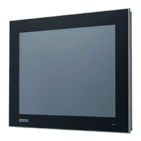
Vtron L-PH4618 User manual

User Manual
VTRON LCD Display Panel
V1.0
VTRON
http:// www.vtron.com
E-Mail: info @ vtron.com
All rights reserved

User Manual VTRON LCD Display Panel
This manual is the copyright property of VTRON. Without prior written approval from
VTRON, any part of this manual shall not be duplicated or distributed in any way or
by any means.
This manual is subject to changes without prior notice.
This product may allow you to use the third party’s software or upload, download the
third party’s works, including articles, images, video or software, but VTRON does not
own or provide such third party’s works. Your use of the above-mentioned third party’s
works means that you agree to use such works without infringing or breaching the
rights of the third party, and VTRON does not assume any liability for your use.
VTRON and Digicom are the registered trademarks of VTRON. Windows is the
trademark or registered trademark of Microsoft in the USA and/or other countries
(regions). Other product names and company names mentioned in this document may
be the trademarks of their respective owners.
Notice
This manual is designed for the introduction to the LCD display panel developed by
VTRON. The specific configurations and functions shall be in accordance with the
purchase contracts signed with the customer. The functions and display interface of the
product you order might differ from those introduced in this manual.
Statement
Products as introduced in this manual are Class A products that may cause radio
interferences in domestic environment. Practical measures should be taken when
necessary.
Currently, the use of LCD display panel shall not last for more than 20 hours each
day due to the technical limitation of the panel manufacturers. Otherwise, the long time
use may cause some aging and Black Mura problems, which may result in some
damages to the panel. In such case, VTRON has the duty to help repair the product. But
VTRON assumes no liability for such kind of damages, so the necessary fee is needed
for the repair.

User Manual VTRON LCD Display Panel
This product has passed strict tests before delivery. However, improper use
may cause electric shock or fire. To ensure safety, extend the service life of this
product and maximize its performance, please read carefully the following items
before using this product, and strictly observe the relevant safety precautions.
If the following situations appear, plug off the power connector from the socket and
turn to qualified technician for repair:
a. The power cable or power connector is damaged or worn out;
b. The panel drops down to the floor or its
cover is damaged;
c. Exception occurs, and the panel still
cannot operate normally even when you
have acted according to the instructions.
d. Foreign object or liquid falls into the unit;
e. Unusual noise or smell gives out;
Inside the panel, there exists high voltage,
and there are no user serviceable
components. To avoid the relevant danger,
please do not open the cover. If repair is
needed, please turn to the qualified
technician.
Safety Precautions
!

User Manual VTRON LCD Display Panel
Locate the panel in the place with good ventilation, moderate temperature and free
from dampness and direct sunshine.
The opening on the enclosure is used for the
heat dissipation of the components inside.
Pay attention not to block the openings when
locating the unit.
Do not place the unit inside any embedded equipment, unless there is any good
ventilation device.
To avoid the falling of the panel, do not place the
panel on any uneven surface.
Do not use the panel near the water source, in the
damp basement or other similar environment.
To avoid unnecessary accidents, please cut off
the power supply during lightning storms.

User Manual VTRON LCD Display Panel
Contents
1. Display Panel Overview............................................................................................. 1
1.1 System Features and Functions...................................................................................................1
1.2 Technical Parameters ..................................................................................................................2
1.2.1 Display Panel Parameters.....................................................................................................2
1.2.2 Interface Parameters.............................................................................................................5
1.2.3 Product Outline Dimensions................................................................................................6
1.3 Interface Overview....................................................................................................................11
2. Remote Control......................................................................................................... 12
3. OSD Menu Operation .............................................................................................. 15
4. Connection Diagram for Display Panel (2×2)........................................................ 21
5. Loop Connection Diagram....................................................................................... 22
6. Installation of Display Panel.................................................................................... 23
7. Use of Display Panel................................................................................................. 24
7.1 System Startup/Shutdown.........................................................................................................26
7.2 Display Signal Source...............................................................................................................27
8. Daily Maintenance.................................................................................................... 27
9. Contact us.................................................................................................................. 29
User Manual VTRON LCD Display Panel
- 1 -
1. Display Panel Overview
1.1 System Features and Functions
L-xxxxx8 products are LCD display panels developed for large-screen video wall
system to realize display of all the input signals.
L-xxxxx8 LCD display panels have the following functions and features:
Support the input of DRGB signal.
Support serial port loop control.
Support entire wall on/off function.
Automatic parameter saving function, able to memorize the adjusted
parameters.
Able to normally display the picture even when the display signal input cable
is plugged out and then plugged in.
Support large-screen display wall application administration software VCMS
(optional).
The VCMS (VTRON LCD Display Management System) software is the
application administration system developed, designed and produced by
VTRON for the large-screen video wall. It is used to control the hardware
equipment in the large-screen display wall system so as to realize the
administration and control of various signal windows and application
windows of the wall. For the detailed configuration and operation instruction
of VCMS, please refer to the user manual of VCMS software.

User Manual VTRON LCD Display Panel
- 2 -
1.2 Technical Parameters
1.2.1 Display Panel Parameters
L-PH4618/
L-PH4618(L)
display panel
Screen size
46″
Screen aspect ratio
16:9
Physical resolution
1920×1080
Dot pitch (mm)
0.530(H) ×0.530 (V)
Display area (mm)
1018.08 (H) ×572.67 (V)
Brightness
L-PH4618(L)
Min.400cd/m2 ;Typ.500cd/m2
L-PH4618
Min.600cd/m2;Typ.700cd/m2
Contrast ratio
Min.2500:1 ;Typ.3500:1
Viewing angle (H/V)
Min.178°/178°
Service life
50000 hours
Power
consumption
L-PH4618(L)
Max:130W
L-PH4618
Max:180W
Power supply
100~240VAC,50~60Hz
Weight
21 Kg
L-PH4628/
L-PH4628(L)
display panel
Screen size
46″
Screen aspect ratio
16:9
Physical resolution
1920×1080
Dot pitch (mm)
0.530(H) ×0.530 (V)
Display area (mm)
1018.08 (H) ×572.67 (V)
Brightness
L-PH4628(L)
Min.400cd/m2 ;Typ.500cd/m2
L-PH4628
Min.600cd/m2;Typ.700cd/m2
Contrast ratio
Min.2500:1 ;Typ.3500:1
Viewing angle (H/V)
Min.178°/178°
Service life
50000 hours
Power
consumption
L-PH4628(L)
Max:100W
L-PH4628
Max:120W

User Manual VTRON LCD Display Panel
- 3 -
Power supply
100~240VAC,50~60Hz
Weight
21 Kg
L-PH5518(L)
display panel
Screen size
55″
Screen aspect ratio
16:9
Physical resolution
1920×1080
Dot pitch (mm)
0.630(H) ×0.630 (V)
Display area (mm)
1209.6 (H) ×680.4 (V)
Brightness
Min.400cd/m2 ;Typ.500cd/m2
Contrast ratio
Min.2500:1 ;Typ.3500:1
Viewing angle (H/V)
Min.178°/178°
Service life
50000 hours
Power consumption
Max:220W
Power supply
100~240VAC,50~60Hz
Weight
27 Kg
L-PH5528/
L-PH5528(L)
display panel
Screen size
55″
Screen aspect ratio
16:9
Physical resolution
1920×1080
Dot pitch (mm)
0.630(H) ×0.630 (V)
Display area (mm)
1209.6 (H) ×680.4 (V)
Brightness
L-PH5528(L)
Min.400cd/m2 ;Typ.500cd/m2
L-PH5528
Min.600cd/m2;Typ.700cd/m2
Contrast ratio
Min.3000:1 ;Typ.4000:1
Viewing angle (H/V)
Min.178°/178°
Service life
50000 hours
Power
consumption
L-PH5528(L)
Max:220W
L-PH5528
Max:240W
Power supply
100~240VAC,50~60Hz
Weight
27.5 Kg

User Manual VTRON LCD Display Panel
- 4 -
Video wall
Quantity of rows and columns
Rows(M) ×Columns (N)
without limitation
Signal input
DRGB
DVI-D
Input/output
loop control
interface
DB9F
RS232
Operating
environment
Temperature
0-40℃
Relative humidity
20﹪-85﹪
Storage
environment
Temperature
-10℃-55℃
Relative humidity
10﹪-90﹪

User Manual VTRON LCD Display Panel
- 5 -
1.2.2 Interface Parameters
Signal input channel
DRGB port
Digital
Connector type
DVI-D
Signal format
TMDS
Dot clock range
27MHz ~148.5MHz
Horizontal scanning frequency range
36.25KHz~67.5KHz
Vertical scanning frequency range
50Hz~60Hz
Resolution range
640×480~1920×1080
Color depth
24bit
Control port
Serial port control and control loop-in
Connector type:
DB9F
Serial port type:
RS232
Data format:
8 data bits, 1 stop bit, no check bit
Baud rate:
9600
Input signal amplitude:
±3V~±15V
Output signal amplitude:
>±4V
Control loop-out
Connector type:
DB9F
Serial port type:
RS232
Data format:
8 data bits, 1 stop bit, no check bit
Baud rate:
9600
Input signal amplitude:
±3V~±15V

User Manual VTRON LCD Display Panel
- 6 -
1.2.3 Product Outline Dimensions
Outline dimensions of L-PH4618 display panel:

User Manual VTRON LCD Display Panel
- 7 -
Outline dimensions of L-PH4618 (L) display panel:

User Manual VTRON LCD Display Panel
- 8 -
Outline dimensions of L-PH4628/L-PH4628 (L) display panel:

User Manual VTRON LCD Display Panel
- 9 -
Outline dimensions of L-PH5518 (L) display panel:

User Manual VTRON LCD Display Panel
- 10 -
Outline dimensions of L-PH5528/L-PH5528 (L) display panel:

User Manual VTRON LCD Display Panel
- 11 -
1.3 Interface Overview
SN
Name
1
Power input port
2
ON/OFF button
3
RS232 in/out port
4
USB ports
5
HDMI port
6
DVI port
7
VGA port
8
PC audio port (currently unavailable)
9
Video input ports
10
Video output ports(currently unavailable)
11
Audio output ports
12
YPbPr ports
13
SV-Y/C input ports
14
Audio input ports
Note:
Please use the cable provided by VTRON. Otherwise, the signal quality may be
affected.

User Manual VTRON LCD Display Panel
- 12 -
2. Remote Control
Precautions for remote control
The remote control shall be pointed directly to the receiving window. Any object
between the remote control and the receiving window may affect the normal
operation of the remote control.
The remote control shall be protected from any vibrant shake. The remote control
shall not be set or placed under direct sunshine. Otherwise, the heat may deform
the remote control.
The remote control may malfunction when the receiving window of the host is
under direct sunshine or strong light. In this case, please change the lighting angle
or the panel angle, or operate the remote control closer to the receiving window.
The remote control distance may be affected in case of insufficient battery voltage.
In this case, please replace with new batteries. If the remote control is idle for a
long time or the battery is used up, please remove the battery. Otherwise, the
battery leakage may erode the remote control, making it unusable.
Do not use batteries of different types. Do not use new batteries together with old
ones. Be sure to replace batteries in pairs.
Do not throw batteries into fire, recharge or decompose them. Please dispose of
the batteries according to the relevant environment protection regulations.

User Manual VTRON LCD Display Panel
- 13 -
Key name
Function description
Standby
The key for switching between
normal state and standby state
Mute
The key used to enable/disable
sound function
Number keys
0~9
The number entry key
F1
The key used to
freeze/defreeze the image
Sound mode
The key used to switch sound
modes
Picture mode
The key used to switch picture
modes
Arrow key
Up/down: select function
Left/right: adjust the value of
the menu item
OK
The confirmation operation
Key
Volume +/-
The key used to
increase/decrease volume
Menu
The key used to display main
menu and return to the upper
level menu
Source
The key used to display signal
source selection menu
Display
The key used to display/cancel
the display panel’s address
number
Time set
The key used to shut down the
display panel at preset time
Zoom
The key used to switch the
display modes
Color
temperature
The color temperature
switching key
Play
Operation in USB mode (not
used)
Pause

User Manual VTRON LCD Display Panel
- 14 -
Stop
Rotate
Previous
Next
Reverse
Forward
Battery installation method for remote control:
Remove the battery box cover, install two AAA (1.5V each) cells, ensuring that the
battery polarity is consistent with the polarity marks (+ and -) inside the battery box.
Note: The appearance of the remote control may be different from the figure. Please
refer to the actual product.

User Manual VTRON LCD Display Panel
- 15 -
3. OSD Menu Operation
Signal source selection
Press the “Source” key on the remote control, and the “input signal source” menu
will be displayed on the screen. Press the “ ” and “ ” key on the remote
control to select the signal source, such as Video 1, Video 2, Video 3, Video 4,
S-terminal, component, PC, HDMI and DVI. Press the “OK” key on the remote
control or the “MENU” key on the panel, and then the display panel will switch to
the input signal source you have selected.
Table 3-1 Description of Signal Source Menu
Key name
Corresponding
input port
Description
Video 1
AV-1
Video channel 1,
loop-in channel
Video 2
AV-2
Video channel 2
Video 3
AV-3
Video channel 3
Video 4
AV-4
Video channel 4
S-terminal
SV-Y,SV-C
S-VIDEO channel
Component
Y,Pb,Pr
YPbPr channel
PC
VGA
VGA channel
HDMI
HDMI
HDMI channel
DVI
DVI
DVI channel
Main menu
Press the “Menu” key on the remote control or the “MENU” key on the panel, the
main menu will be displayed on the screen.
This manual suits for next models
6
Table of contents
Popular Industrial Monitor manuals by other brands

Azbil
Azbil ACTIVAL+ Specifications & instructions

Digital Equipment
Digital Equipment Pro-face FP2500-T41 user manual

Hope Industrial Systems
Hope Industrial Systems HIS-UM15-***H user manual

Raven
Raven RGL 600 Operation manual

Toshiba
Toshiba LTA057A341F specification

Hatteland
Hatteland JH 15C06 CTX user manual

Advantech
Advantech FPM-3060G Series user manual

freetronics
freetronics DMD Getting started

Azbil
Azbil QY5010S1000 Specifications & instructions

C-MORE
C-MORE EA1-S6ML quick start guide

CHIEF
CHIEF ConnexSys Series installation guide

Synergy Global Technology
Synergy Global Technology LCDR7U19-08 user manual