Bernhard Express Dual 4000DX User manual

EXPRESS DUAL 4000DX
Please read this manual carefully before using the Express Dual 4000DX.
This manual should be kept in a safe place so that it can be used for future reference.
Touch Screen Model
User’s Guide &
Instruction Manual
EXPRESS DUAL 4000DX

EXPRESS DUAL 4000DX
© Bernhard and Company Limited
NOTES
.....................................................................................................................................................................................................................................................................
.....................................................................................................................................................................................................................................................................
.....................................................................................................................................................................................................................................................................
.....................................................................................................................................................................................................................................................................
.....................................................................................................................................................................................................................................................................
.....................................................................................................................................................................................................................................................................
.....................................................................................................................................................................................................................................................................
.....................................................................................................................................................................................................................................................................
.....................................................................................................................................................................................................................................................................
.....................................................................................................................................................................................................................................................................
.....................................................................................................................................................................................................................................................................
.....................................................................................................................................................................................................................................................................
.....................................................................................................................................................................................................................................................................
.....................................................................................................................................................................................................................................................................
.....................................................................................................................................................................................................................................................................
.....................................................................................................................................................................................................................................................................
.....................................................................................................................................................................................................................................................................
.....................................................................................................................................................................................................................................................................
.....................................................................................................................................................................................................................................................................
.....................................................................................................................................................................................................................................................................
.....................................................................................................................................................................................................................................................................
.....................................................................................................................................................................................................................................................................
.....................................................................................................................................................................................................................................................................
.....................................................................................................................................................................................................................................................................
.....................................................................................................................................................................................................................................................................
.....................................................................................................................................................................................................................................................................

EXPRESS DUAL 4000DX
© Bernhard and Company Limited
EXPRESS DUAL
BERNHARD & CO. LIMITED
Bilton Road • Rugby • England • CV22 7DT
Tel +44 1788 811600 • Fax +44 1788 812640
Email: info@bernhard.co.uk
USA Toll Free 1-888 GRIND IT (1-888 474 6348)
ED4000DX Precison Reel/Cylinder Grinder
Welcome to the Bernhard Express Dual 4000DX. If cared for and operated
correctly this machine will give you years of good service.
This manual will enable you to obtain the best results from your Express Dual so
please read it thoroughly before using your machine.
If you have any service or operational issues please contact your distributor or
phone our technical support hotline
Technical Helpline (USA only) 1-888 474 6348
Rest of World: UK Head Ofce, England (+44) 1788 811600
Email: support@bernhard.co.uk
Technical FAQs can be found on our web site: www.bernhard.co.uk
When ordering spare parts please quote the machine type and serial number.
THE MANUFACTURERS ACCEPT NO RESPONSIBILITY FOR ANY SITUATION ARISING FROM THE
FITTING AND/OR USE OF NON-ORIGINAL SPARE PARTS.
Contents
Identication of Pictograms 3
Safety 5
Installation 6
Identication of Tools and Equipment 8
Understanding the Machine 9
In Frame Grinding 11
Electrical Fault Finding 21
Maintenance 23
Part Lists and Exploded Diagrams 29
Lift Table Instructions 48
Quick Start Guide 58
ED4000DX Touchscreen – 1003.4/ENG/2017RB
Please quote this serial number on all
correspondence:
Serial #:

© Bernhard and Company Limited 4
EXPRESS DUAL 4000DX
BEWARE! HIGH VOLTAGE
1. Identication of Pictograms
MAXIMUM LIFT PLATFORM
LOAD - 250 KG (550 LBS)
BEWARE!
TRAPPING FEET OR OTHER OBJECTS
WHEN LOWERING LIFT PLATFORM
MAXIMUM GRINDSTONE
DIAMETER 150mm
MAXIMUM SPEED 4000 Rev/Min
RUNS AT 2200 Rev/Min
BEWARE!
MOVING GRINDSTONE AND SHAFT
REEL ROTATING AT BETWEEN
147 AND 255 Rev/Min
TOTAL WEIGHT OF MACHINE (KG)

© Bernhard and Company Limited 5
EXPRESS DUAL 4000DX
WEAR EYE, EAR AND BREATHING
PROTECTION
1. Identication of Pictograms (Continued)
POINTS FOR ATTACHING
LIFTING EYES
BEWARE!
MOVING COMPONENTS KEEP HANDS
AND OTHER OBJECTS CLEAR
GRINDSTONE START CONTROL
REEL START CONTROL
STOP CONTROL
TRAVERSE START CONTROL
ENGAGE / DISENGAGE (INCREASE /
REDUCE) GRINDSTONE FEED

© Bernhard and Company Limited 6
EXPRESS DUAL 4000DX
2.1 This machine is designed and manufactured ONLY for grinding lawn mower reels, rollers,
groomers and verticut units, and MUST NOT be used for any other purpose.
2.2 This machine should be installed, operated and maintained by competent personnel who
have received adequate training.
2.3 Before carrying out any work on the machine, other than grinding, ALWAYS SWITCH OFF
the main electrical supply, or remove the power lead from its socket.
2.4 ALWAYS operate the machine with the guards in position.
2.5 NOISE - Owing to the widely varying conditions of use, noise emissions may vary
considerably. There may be occasions when the safe noise level may be exceeded (see
note on noise emission). In this case adequate ear protection MUST be worn.
2.6 NEVER t or use a grinding wheel (or other spares) other than those supplied specically
for use on the EXPRESS DUAL (Warranty will be invalidated).
2.7 NEVER t or use a grinding wheel which has been dropped or subjected to any other form
of abuse.
NOTE: Grinding wheels should be tted ON LY by competent, trained personnel.
2.8 NEVER leave rags or tools on the machine or wear any loose clothing or other articles
which could be caught in moving components.
2.9 NEVER allow any combustible materials to be placed on or around the machine.
2.10 ALWAYS ensure that all parts of the cutting unit being ground are securely xed.
2.11 ALWAYS ensure that all electrical connections are sound and all cables are safely routed.
2.12 ALWAYS carry out cleaning and maintenance of the machine as instructed in this manual
(Refer to safety note 2.3).
2.13 STAY ALERT. Watch what you are doing. NEVER operate the machine when tired, or
under the inuence of drugs or alcohol.
If a lift table is tted NEVER attempt to lift in excess of the rated capacity, and always
ensure that the area is clear before lowering the load.
2. Safety
© Bernhard and Company Limited 7
EXPRESS DUAL 4000DX
3. Set Up and Installation
Fig: 3.2
3.1 Handling
If the machine is crated, it can be moved by a suitable fork lift truck or pallet truck under
the pallet (skid). Once the lid and sides of the crate are removed, a fork lift truck may be
used under the lifting members of the machine chassis.
The machine can be lifted off the pallet using suitable lifting tackle through 4 lifting eyes
(provided) tted at the points indicated on the top corners of the machine.
The total weight of the machine is indicated on the machine plate and also at the front of
this manual.
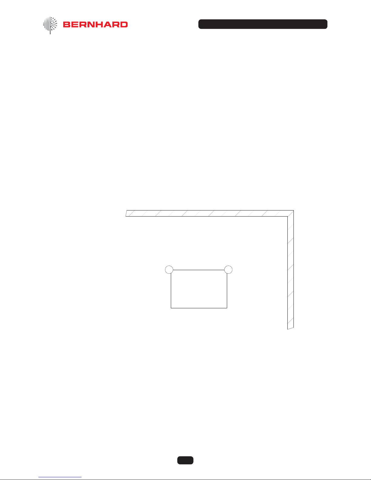
3.2 Location
The machine should be located in a well lit environment with adequate headroom. For
ideal operation, the machine should be accessible from the front, rear and at least one
side, with clearance around it as indicated in the sketch (Fig. 3.2).
3.3 Leveling
The machines should, ideally, be placed on a solid level oor, and this should be checked
by placing a spirit level on the table. Check the level in both directions. Steel shims should
be placed under the feet as necessary to ensure that the machine is rm and level. Bolt
holes are provided in the feet which can be used for xing down if required.
NOTE Ensure that the packing under the feet is correct before tightening the bolts, otherwise
twisting of the frame may occur.
1.5m (5 ft)
1.5m (5 ft)
ENSURE ADEQUATE SPACE FOR
LOADING UNITS AND FOR A LIFT
TABLE (IF FITTED)
FRONT OF MACHINE

© Bernhard and Company Limited 8
EXPRESS DUAL 4000DX
3.4 Electrical Supply
USE A QUALIFIED ELECTRICIAN
The EXPRESS DUAL is supplied with a .75 kW (1 HP) single phase main (grind) motor
plus 2 fractional HP motors, for spin and traverse.
Power connection to the machine is via plug and socket termination of the lead supplied.
Connection is at the rear of the main electrical control box on the right hand end of the
machine.
Ensure that any cable or conduit run to the machine does not constitute a hazard to the
operator or other personnel.
Machine should be connected to the supply via a 20A breaker.
The top of the reel and the top of the grinding wheel should both move away from the
front of the machine (i.e. both rotate clockwise when viewed from right hand end of the
machine). In this way, the reel and grinding wheel are moving in OPPOSITE DIRECTIONS
at the point of contact.
3.5 Preparation
If the machine has been
received in a crate, the handles
on the control wheels should be
removed from the underneath of
the control wheels and retted to
the top (see Fig. 3.5).
It is important that the protective
lm on the main shaft is
removed prior to using the
machine. This can be done
using a WD40®or similar
product (not gas/petrol) and then
drying the shaft with a clean, dry
cloth so that the grinding wheel
assembly moves freely along the
whole length of the shaft.
A spray lubricant, such as WD40®, should be applied to all bare metal surfaces and
moving parts; this includes the reversing bar and the shafts (along which the fork assembly
traverse, but NOT THE MAINSHAFT).
The mainshaft should be washed down as instructed in the maintenance section of this
manual. The feed control screws are normally coated with Molycote®, and may be washed
down with WD40®if required and recoated with Molycote®(or similar anti friction coating)
when dry.
Fig: 3.5
3. Installation (Continued)

© Bernhard and Company Limited 9
EXPRESS DUAL 4000DX
4. Indentication of Tools and Equipment
The items below may not necessarily be included since the tools and equipment
supplied will vary according to the machine specication.
4.1 Express Dual 4000 and 4000DX (see illustrated parts list).
A9502 Adjustable Mounting Bracket Set (Fitted) ........................1
A6505 Grind Stone (Fitted)..................................................................1
A6737 Diamond Dresser (In Spin Drive Support) .......................1
A2719 Grinding Wheel Wrench..........................................................1
A6342 Pressure Plate ............................................................................1
A4095 Plain Drive Rod Short..............................................................1
A4134 Square Drive Rod Short (Fitted To Cable Drive) ...........1
A4066 Long Ball Handled Allen Key.................................................1
A2720 Large Hex Key............................................................................1
A2706 3/16 T Handled Allen Key.......................................................1
A4097 Plain Shaft Driver ......................................................................1
A4063 Large Two Pin Sprocket Driver.............................................1
A4133 Drive Kit - Female Splines......................................................1
A9535 Adj. Sprocket Driver Complete .............................................1
A9534 Eccentric Pin For Adj Sprocket Driver ...............................3
A2722 Molycote Paste...........................................................................1
A6847 Molycote Brush...........................................................................1
A4087 Multix Channels .......................................................................1
A2712 8mm Allen Key ...........................................................................1
A8786 Pack of Spare Fuses................................................................1
A2708 3mm Allen Key ...........................................................................1
A3306 22mm 1/2 Drive Socket...........................................................1
A6603 Guarantee Certicate ..............................................................1
A6615 Operating Instructions .............................................................1

© Bernhard and Company Limited 10
EXPRESS DUAL 4000DX
5. Understanding the Machine
5.1 General Principles
The EXPRESS DUAL is designed to grind reels completely assembled, or as a separate
“loose” reel. A Loose Reel Kit (Available as an optional extra, at additional cost) is required
for this operation.
The basic principle of the EXPRESS DUAL is to grind mowers in exactly the same
conditions that they mow in. The grinding wheel takes the place of the grass, striking the
reel in relatively close proximity to that found in the mowing position.
5.2 Basic Requirements
It is important that grinding the cutting unit, when it remains completely assembled, takes
place under the following conditions:
5.2.1 The reel bearings MUST be in good condition, adjusted correctly and if the roller is to be
located on the roller mounting brackets or the multix brackets, the roller bearings MUST
also be in good condition.
5.2.2 The bedknife must be ground separately on a machine, such as the ANGLEMASTER
bedknife grinder which can guarantee that the blade will be perfectly STRAIGHT and at
whilst mounted on the bedbar.
During the reel grinding process, it is advisable that the bedknife/bedbar assembly is
replaced in the unit after having been ground. On many units the bedknife/bedbar is an
integral part of the frame and contributes to its strength and rigidity.
5.2.3 The reel or bedknife must be adjusted away from one another to allow free rotation (There
should be no reel to bedknife contact!).
5.2.4 It is essential that all work to be carried out on the mowing unit (all mower repairs
– bearings, seals, roller work, etc.) has been completed prior to grinding the reel. The last
operation of all, apart from nal setting reel to bedknife, is the actual grinding of the reel
in-frame.
It is essential that the unit is held totally rm during the grinding process. When in frame
grinding, the front of the unit must be held rmly in the multix brackets or on the front
roller brackets.
5.2.5 It is essential that the unit is held totally rm during the grinding process. When in frame
grinding, the front of the unit must be held rmly in the multix brackets or on the front
roller brackets.
The rear of the unit will be held by the radiused pressure bar at the rear of the grinder.

© Bernhard and Company Limited 11
EXPRESS DUAL 4000DX
5. Understanding the Machine (Continued)
5.3 Machine Functions
The EXPRESS DUAL has separate motors driving the different functions of the machine,
all are turned on and off from the control panel in ‘manual’ mode or by the machine
program in ‘auto’ mode. These functions are as follows:
5. 3.1 Traverse
This motor and the accompanying drive mechanism controls the automatic movement of
the grinding wheel along the mainshaft.
5.3.2 Reel/Spin drive
This motor drives the reel through a exible shaft driving from a drive mechanism under
the table. It is a three phase motor controlled by an inverter for varying output speed.
5.3.3 Grinding Wheel
A motor situated under the table, drives the mainshaft and grinding wheel at around 2200
rpm.
5.3.4 Stop
Pressing the stop button shuts off all motors and locks into the “off” position. None of the
start buttons will operate until the stop button has been unlocked by twisting the knob
counter-clockwise to release it (and the m/c control error warning has been reset).
NOTE The machine must NOT be stopped when there is contact between the reel and grinding
wheel, except in cases of emergency.
5.3.5 Reset Button (see also Electrical Fault Finding section)
If the main motor is subject to a voltage drop or overloading, the current being drawn
will rise and a safety device will automatically shut the grinder off. The overload trip
device (thermal overload contactor) is attached to the main motor contactor in the main
electrical control box which is located within the safety guard on the right hand side of the
machine.(looking from the front). The (red) reset button is on this overload.
The trip setting will vary with the electrical specication of each machine and is normally
set to the full load current of the motor. If the overload trip has shut off the grinder it can be
reset by pushing the reset button after a few minutes delay. This will allow the grinder to be
re started.
NOTE The overload is variable and should be adjusted, if required, as indicated in the appropriate
service bulletin.
Other motor, VSD inverter (reel spin speed control), and other electrical devices are
protected by individual fuses located on the electrical control panel accessible via key
entry to the enclosure on the right hand side of the guard.

© Bernhard and Company Limited 12
EXPRESS DUAL 4000DX
6.1.1 Mower Preparation
Units of up to 36” long can be ground
in frame, this includes most machines
including Greens mowers and Fairway
units. In order to spin / drive the reel,
one end of the reel shaft drive must be
exposed. This will require the removal
of the hydraulic motor, the chain / belt
or cover depending on which type
of unit is being ground. This should
be done before the mower is on the
grinder (see example Fig. 6.1).
Ensure that the mower is clean and
that both reel and roller bearings are
in good condition. Also ensure that
the bedknife has been sharpened, if
necessary, and replaced with a small
amount of clearance between it and the reel.
FOLLOW THE ILLUSTRATED INSTRUCTIONS IN THE QUICK START
GUIDE AT THE END OF THIS MANUAL
6.1.2 FOLLOW THE SCREEN PROMPTS
Press Auto icon button to progress from the welcome screen to automatic mode
– display advances to next screen
Screen prompts to:
Ensure traverse is not engaged
To mount mower
To engage clamp
6.1.3 Unscrew the traverse engagement screw until it is released from the traverse chain so that
fork/grindstone can be traversed manually along the mainshaft.
6. In-frame Grinding
Fi g: 6.1

© Bernhard and Company Limited 13
EXPRESS DUAL 4000DX
6. In-frame Grinding (Continued)
6.2. Mounting Mower
The mainshaft / Grinding stone should be wound down to its lowest position and the unit
placed on the table. The unit should then be carefully moved towards the multix brackets
or front roller brackets, which can be adjusted in any direction to allow the unit to be xed
in such a position that the grinding wheel can be raised towards the reel without coming
into contact with either the bedknife or the front roller/groomer.
6.3. Clamping
With the mower correctly positioned the radiused pressure bar) is moved forward to rest
on the rear of the mower and locked in position by pressing the key on the operator display
panel on the operator control panel downwards. The operator should release the key as
the pressure bar engages the cutting unit thus retaining pressure on the mower until the
grinding operation is completed. A backing up plate is supplied to protect the rear of the
units and to evenly disperse the force of the pressure bar across the width of the mower
(see Fig. 6.3.1.).
Fi g: 6.3 .1
© Bernhard and Company Limited 14
EXPRESS DUAL 4000DX
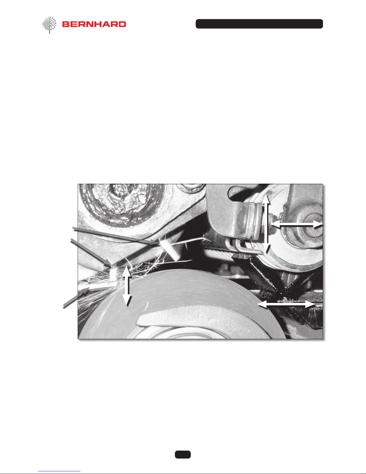
To ensure that the correct position for the mower unit has been achieved, both control
wheels (right hand and left hand) should be wound in a clockwise direction so that the
grinding wheel may be placed to contact each end of the reel evenly. If the grinding wheel
touches the bedknife or any part other than the reel, the whole unit must be moved by
adjusting the position of the multix brackets or roller brackets. The exact position required
will be easily seen by looking along the mainshaft from one end of the machine as the
stone is raised to check that the point of contact is in a suitable position (see Figure 6.3.2.)
Rotate hand wheels anti-clockwise to move grinding wheel away from reel. It is important
that the grinding wheel should clear the highest blade along the full length of the reel
before proceeding.
NOTE If the cutting unit has no front roller tted so that the multix brackets are used then, once
the correct position for any particular unit has been nalised a “set up guide” should be
completed and led for future reference so that the identical multix brackets positions can
be used for all subsequent applications on the same type of unit.
6. In-frame Grinding (Continued)
Fig: 6.3.2
Reel
blades
Front Roller position
is adjustable
Grind stone has to contact
reel blades for sharpening
without touching anything else
Adjustable Front
Roller support
Position of
bedknife is
adjustable

© Bernhard and Company Limited 15
EXPRESS DUAL 4000DX
6.4 Linking Up The Reel Drive Unit to the Reel
Machines are supplied with the reel drive motor under the table and a exible drive which
can be attached to either end of the machine do not have to be prepared before the mower
unit is placed on the table, as the complete drive unit can be moved to either side of the
table with a mower unit in place.
6.4.1 Select the attachment with which to drive the reel. If the reel sprocket, gear or pulley
is secured with a nut it may be easier to use a standard socket together with a 1/2”
square end driver. Ensure the nut is tight as the direction of rotation may tend to unscrew
it. Ensure that the drive shaft is through the exible coupling/driver before setting the
machine on the table and that the whole unit is at the correct end of the table.
Alternatively it may be easier to drive directly onto the sprocket using one of the pin or
adjustable type sprocket drivers tted to the plain drive rod.
6.4.2. When the cutting unit is in place and rmly xed into the multix brackets, or front roller
brackets, and the rear clamped with the radiused pressure bar, adjust the drive unit left or
right so that the appropriate drive rod will reach the end of the reel shaft. Tighten unit in
place.
Adjust the height and position, forwards and backwards and up and down, of the cable
drive support so that the shaft is square with the driven end of the reel, and tighten clamps
to hold it in place.
The black lobed hand screw allows the drive head to be moved along the square support
shaft to adjust the height of the drive, while the 5/8” hex headed socket screw allows the
support shaft to be clamped at any desired angle, and also allows the whole assembly to
be moved left or right along the machine bed to engage in the drive mechanism on the
reel.
The drive head of the shaft can also be slid through it’s support for further adjustment or
nal connection/ disconnection of drive.
6.4.3 Tighten the drive rod via the allen screw in the exible coupling onto the at of the drive
shaft.
6. In-frame Grinding (Continued)

© Bernhard and Company Limited 16
EXPRESS DUAL 4000DX
6. In-frame Grinding (Continued)
6.4.4 Moving the exible Shaft
There is a lay shaft socket at both ends of the
machine into which the exible drive can be
engaged as required. The other end of the
exible shaft can be disconnected if required
but this would not generally be necessary as the
bracket and shaft would normally be moved as
an assembly
The exible drive shaft can be detached
from its socket on the end of the machine by
pulling sharply on the shaft, to release it from
a spring loaded ball detent. (Earlier units by
rst removing the spring retainer (R-pin)),
and withdrawing the complete shaft (see Fig.
6.4.2.2.) When replacing the shaft, ensure that
it is properly engaged in the lay shaft socket.
By loosening the socket screw and allowing
the clamp nut, under the table, to twist through
approximately 90 degrees, the whole assembly
can be lifted clear of the table, and moved to the
other side of the mower unit if required.
Press “next” icon on operator display – display advances to next screen.
Fig. 6.4.4.2
© Bernhard and Company Limited 17
EXPRESS DUAL 4000DX
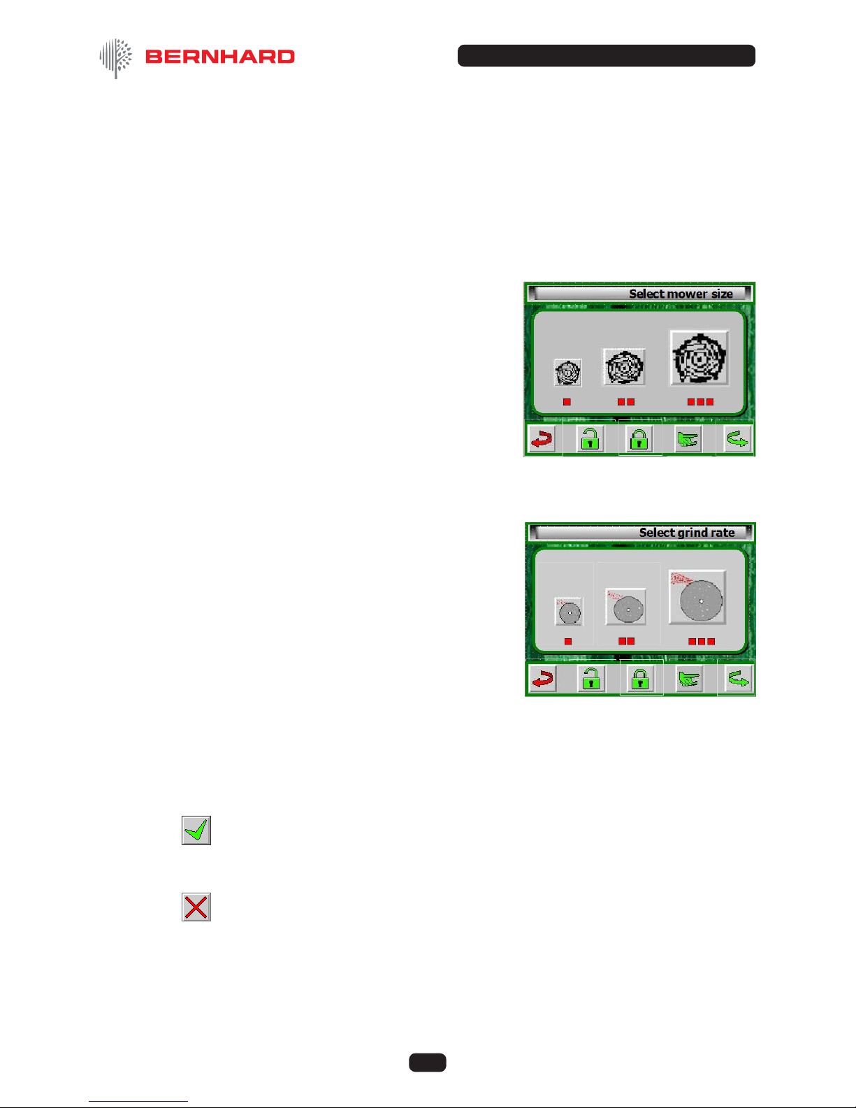
6.5 Actual Grinding
Screen requests size of mower.
6. 5.1 Press the relevant icon to select size of mower:
nSmaller units (or Greens)
n n Medium sized units (or Tees / Light
Fairway)
n n n Large units (or Fairway)
Display advances to the next screen.
Screen requests type of grind required.
6.5.2 Press the relevant icon to select type of grind required:
n“touch up” (mower needs little
sharpening, probably part of a regular
sharpening regime)
n n “maintain” (blades need just a little more
material removing to get a good edge) or
n n n “rectify” (damaged blades, or a unit rarely
ground or heavily back-lapped)
Display advances to the next screen.
6.5.3 Screen shows selected answers (grind cycle)
CLOSE GUARD FIRST
Press tick (“accept”) icon if OK.(Grind, Traverse and Reel drive motors start – display
advances to the next screen).
or
Press cross (“reject”) icon if you wish to make an alternative selection (display returns to
size of mower question).
6. In-frame Grinding (Continued)
© Bernhard and Company Limited 18
EXPRESS DUAL 4000DX
6. In-frame Grinding (Continued)
6.5.4 Set up of Traverse
With motors running, the screen prompts: “set grind stone to reel” and
“set traverse limit stops”
Traverse the grinding wheel by hand, using the Traverse Engagement Screw until it is at
the extreme point of desired travel. Ensure that the traverse reversing bar is also moved in
that direction and slide the reversing stop up to the grinding wheel traverse assembly and
tighten. Move the grinding wheel to the opposite end of the desired travel and repeat the
operation ensuring that the reversing bar has also been moved in the opposite direction.
This is critical where the grinding wheel cannot pass beyond the end plates if they protrude
below the maximum diameter of the reel.
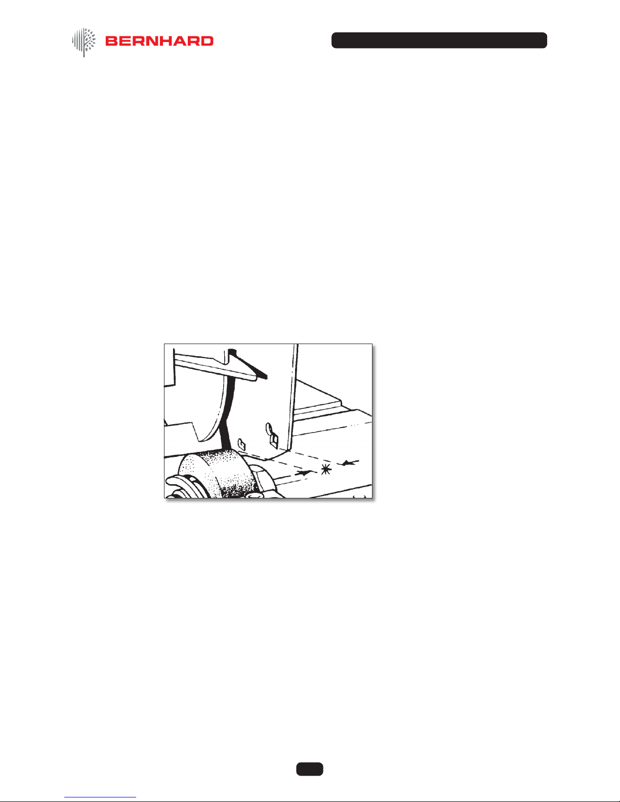
NOTE On the EXPRESS DUAL it is not necessary for the whole width of the grinding wheel to
pass the end of the reel and it SHOULD NOT DO SO EVEN IF SPACE PERMITS (see
Fig. 6.5.4).
Ensure that the leading edge
of grinding stone passes the
end of the reel – but clearance
must be maintained between
stone and end frame of unit.
NOTE: The reversing bar will move approximately ½” (13mm) before the direction of travel is
reversed and will allow the grinding wheel to move with it. It is therefore ESSENTIAL that
this is taken into account when setting the maximum point of travel.
Fig: 6.5.4

© Bernhard and Company Limited 19
EXPRESS DUAL 4000DX
6.6.1 With the stone positioned at the left hand end of the reel, place the left hand on the left
hand control wheel and the right hand on the traverse knob, moving the grinding wheel
along the reel by hand using the traverse engagement screw, wind up the left hand control
wheel clockwise until the grinding wheel strikes and sparks gently against the reel.
6.6.2 Unwind a complete turn to move the stone away from the reel.
6.6.3 Move the grinding wheel to the right hand end of the reel and, using the right hand on the
right control wheel, raise the shaft until the reel again can be gently rotates against the top
of the grinding wheel.
6.6.4 Unwind half a turn.
6.6.5 Go back to the left hand end and repeat the process but this time, after contact has been
made, unwind only sufciently to release the contact.
6.6.6 Go back to the right hand end and repeat the process and again release the contact only
slightly.
6.6.7 Repeat this process on the right hand side of the reel, raising the shaft with your right hand
and moving the grinding wheel along with your left hand. Repeat this process until the
contact all along the reel is light, even and parallel.
6.6.8 Screw in traverse knob to engage power traverse.
NOTE: Check auto traverse is changing direction at correct point at each end of its
movement.
6.6.9 Press “next” icon to start grinding cycle
Screen reads “GRINDING”. Pictures on display animate.
Both handwheels will automatically rotate clockwise to apply a parallel cut to the reel.
After a pre-determined number of traverse passes of the stone along the reel a further in
feed will be applied.
According to the program selected a certain number of in feeds / traverse passes will
follow until the cycle is completed. Both handwheels will then rotate counter-clockwise, to
back the stone away from the reel, and all motors will stop.
(Programme will NOT let a reel “spark-out” with factory set programme parameters)
6. In-frame Grinding (Continued)

© Bernhard and Company Limited 20
EXPRESS DUAL 4000DX
6.6.10 Screen reads “PROGRAM COMPLETE
Press “nished” icon if reel is satisfactory
or
Press “re-do” icon if it needs more grinding, to repeat the whole cycle
or
Press “touch-up” icon if reel is almost there but could do with a “touch up” to nish it off.
6.6.11 Press “nished” icon to advance display to the next screen “Grinding completed”-
remove mower from machine”
6.6.12 Press “unlock” icon to undo clamp and remove mower
6.6.13 Press “next” icon to return to the starting screen
6.7 ALTERNATIVES
6.7.1 If “re-do” or “touch up are selected, (close the guard before selection).
After a pause the motors will re-start and the handwheels will return the grindstone to the
position where the grind cycle nished. Further feeds/traverses will follow until the cycle is
completed once more,
6.7.2 At this time the guard can be opened and the condition of the reel checked.
6.7.3 If the blades are sharp enough Press the “nished” icon.
6.7.4 The display will change to “Grinding completed – remove mower from machine”
screen.
6.7.5 If the blades still need some grinding, the “resume” icon can be pressed, after closing
the guard. After a pause the motors will re-start and the handwheels will return the
grindstone to the position where the grind cycle was paused. The cycle will continue to it’s
conclusion.
6. In-frame Grinding (Continued)
Table of contents
Other Bernhard Grinder manuals


