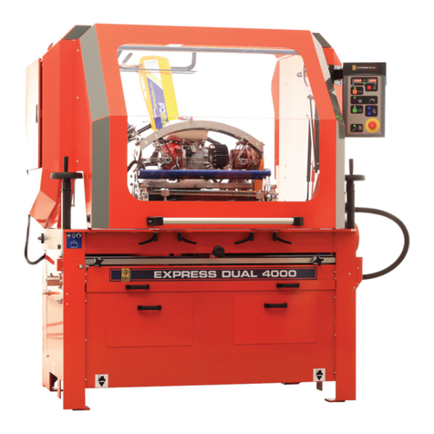
Bernhard Anglemaster 3000 User manual

Please read this manual carefully before using the Anglemaster.
This manual should be kept in a safe place so that it can be used for future reference.
User’s Guide &
Instruction Manual
ANGLEMASTER
3000
Anglemaster 3000 Bedknife Grinder
AM3000_2007/02/ENG/Membrane Control Panel
ANGLEMASTER • AM3000

ANGLEMASTER
BERNHARD AND COMPANY LTD
Bilton Road • Rugby • England • CV22 7DT
Tel +44 1788 811600 • Fax +44 1788 812640
Email: info@bernhard.co.uk
USA Toll Free 1-888 GRIND IT (
1-888 474 6348)
AM3000 Precision Bedknife Grinder
Contents
Identication of Pictograms 3
Control Box Layout 4
Understanding the Machine 5
Safety 6
Set Up and Installation 7
Setting Up 9
Setting Angles of Cut 13
Electrical Fault Finding 16
Maintenance 18
Parts List 19
Wiring Diagrams 35
Bedknife Mounting Guide 38
AM3000_2007/02/ENG/Membrane Control Panel
Please quote this serial number on all
correspondence:
Serial #:
You are now the owner/operator of a Bernhard’s Anglemaster 3000 which,
if cared for and operated correctly, will give you years of good service.
This manual will enable you to obtain the best results from your Anglemaster so
please read it thoroughly before using your machine.
If you have any service or operational problems contact your distributor,
or phone our
Technical Helpline (USA only) – 1-888 474 6348
or
Bernhard and Company Ltd, England – (+44) 1788 811600
or email
or use the technical support feedback form on our web site
www.expressdual.com or www.bernhard.co.uk
When ordering spare parts please quote the machine type and serial number.
THE MANUFACTURERS ACCEPT NO RESPONSIBILITY FOR ANY SITUATION
ARISING FROM THE FITTING AND/OR USE OF NON-GENUINE SPARE PARTS.
2
ANGLEMASTER • AM3000

BEWARE!
HIGH VOLTAGE
BEWARE!
MOVING COMPONENTS KEEP HANDS
AND OTHER OBJECTS CLEAR
1. LIFT HERE
2. DO NOT LIFT HERE
TOTAL WEIGHT OF MACHINE (KG)
WEAR EYE, EAR AND BREATHING
PROTECTION
MAXIMUM GRINDSTONE
DIAMETER 150mm
MAXIMUM SPEED 3800 Rev/Min
BEWARE!
MOVING GRINDSTONE AND SHAFT
Identication of Pictograms
3
ANGLEMASTER • AM3000
© Bernhard and Company Limited

Control Box Layout
TRAVERSE
CONTROL
COOLANT
PUMP
GRINDSTONE
CONTROL
MAGNET
CONTROL
(Bottom)
EMERGENCY STOP
(Twist anti-clockwise to
release)
SERVICE
SWITCH
RESET 0° ANGLE
INCREASE/
DECREASE ANGLE
DESIRED ANGLE
“Where you want to be”
CURRENT ANGLE
“Where you are”
4
ANGLEMASTER • AM3000
© Bernhard and Company Limited

Machine Functions
The ANGLEMASTER has three separate motors driving the grind stone, traverse and
coolant pump respectively. Each has a separate start and stop button on the control panel.
Grind Stone
Directly driven by the main motor at up to 3800 rpm.
Traverse
Powered by a motor/gearbox unit under the grinding head carriage. Drives along a xed,
damped chain run. Traverse is physically engaged using the over-centre lever on the left
front of the carriage.
Coolant pump
Fitted into the top of the coolant reservoir/settlement tank which is located inside the
cabinet in the base of the machine.
Emergency stop
Pressing the large red mushroom headed button will stop ALL motors. The button will be
locked into the off position. No motors will start when their buttons are pressed until the
E-stop is released by twisting the knob counter-clockwise.
Understanding the Machine
5
ANGLEMASTER • AM3000
© Bernhard and Company Limited

1.1 Always wear eye protection when operating the machine
1.2 Never leave rags or tools on the machine or wear loose clothing that could become caught
up in the bedknife, grinding stone or shaft.
1.3 Never allow combustible materials to be placed on or around the machine
1.4 Always ensure that all parts of the bedknife being ground are securely xed.
1.5 Never use the machine for any purpose other than that for which it was designed
1.6 If large units are to be ground, ear defenders should ideally be worn.
(The maximum noise, with a heavy cut on a 36” bedknife has been measured at 85
decibels).
1.7 Ensure that all electrical connections are sound and that cables are safely routed.
1.8 NEVER t or use any grinding stone other than those supplied specically for use on the
ANGLEMASTER.
1.9 NEVER t or use a grinding stone that has been dropped or damaged in any other way
1.10 Always mix and use coolant according to the manufacturer’s instructions.
1.11 Never allow coolant to wash over the control box or other electrical parts.
Extreme caution should be used when removing a bedknife from the ANGLEMASTER.
Ideally protective gloves should be worn.
1. Safety
6
ANGLEMASTER • AM3000
© Bernhard and Company Limited

2. Installation
Hex head
bolt
2.2 Location
The machine should be installed in a well-lit area, set up on a solid oor base of concrete
or similar. Wooden oors should ideally be avoided.
Using a spirit level, laid across / along the traverse rails, the machine can be leveled easily,
suitable metal packing may be placed under the cabinet chassis feet.
2.1 Handling
The weight of the machine is indicated on the plate on
the front of the machine.
If the machine is supplied crated, it can be moved by a
suitable forklift or pallet truck under the crate base (skid).
Once the lid and sides of the crate have been removed,
the machine remains bolted to the base (skid).
LIFTING WITH CHAINS/STRAPS/FORKS MUST ONLY
BE CARRIED OUT AS INDICATED BY LABELS ON
THE MACHINE NOT BY MEANS OF THE TRAVERSE GUIDE RAILS.
2.3 For transit purposes, the blade-mounting bar is locked in position at both ends. Some units
may be shipped with a hex head bolt in the right hand clamp. If so, the clamp lock down
lever is in the tool drawer of the machine cabinet. Remove replace the hex head bolt with
the lever and tighten down.
The hex head bolt on the left-hand clamp should be eased off and adjusted to permit
rotation of the mounting bar with a small amount of resistance.
Do not release the right hand clamp (lock down lever) until the weight has been taken on
the angle control lever. For all subsequent use only the lock down lever will be used to hold
the mounting bar in position. If the lock down lever does not appear to be applying enough
force, the hex head bolt on the left-hand needs to be a little tighter.
7
ANGLEMASTER • AM3000
© Bernhard and Company Limited

2. Installation (Continued)
2.4 Electrical Supply
USE A QUALIFIED ELECTRICIAN.
All motors are dual cycle 220-230V 50/60Hz, single phase induction motors (Except
variable speed traverse motor on DX models which is three phase).
Electrical connection should be via the electrical cable/plug/socket provided and should be
to a 20 Amp breaker.
The main grinding head motor is overload protected, whilst coolant pump and traverse
motors are independently fused.
Ensure that any cable / conduit run to the machine constitutes no hazard to operator or
other personnel.
The machine MUST BE EARTHED.
2.5 Coolant
Check the location of the settlement tray in the
coolant tank on the shelf in the cabinet under
the left-hand side of the machine. It should sit
beneath the collector funnel outlet (inlet into tank
lid). Also check the connection of the coolant
supply hose to the pump outlet.
The soluble additive may be used in the coolant
tank and should be mixed according to the
manufacturer’s instructions (at 1 –1 capful of
additive per FULL tank of water). This uid is
suitable for all types of blade grinding and has
good rust inhibiting properties (if used according
to instructions).
Do not exceed the recommended concentration
as this may lead to “loading” of the grindstone
during usage, which may in turn affect grinding
results.
Sediment in the coolant tank should not exceed
”. Surplus liquid should be returned to the tank
and solid deposits removed at regular intervals,
depending upon workload.
8
ANGLEMASTER • AM3000
© Bernhard and Company Limited

3. Setting Up
1. BRACKET BODY
2. ADJUSTABLE SUPPORT
PLATE
3. LOCKING KNOB A /
ADJUSTABLE LEVER
4. TAPERED SUPPORT PIN
5. SUPPORT CUP
6. LOCKING KNOB
7. CENTRAL JACKING SCREW
8. JACKING SCREW END
EXTENSION
9. KNURLED LOCKING NUT
10. TRUNNION
11. LOCKING KNOB
12. SUPPORT BRACKET
3.1 General
3.1.1 The ANGLEMASTER has a capacity of 40” between mounting brackets for complete
bedknife/bedbar assemblies, or 42” for plain blades clamped directly to the mounting bar.
3.2 Mounting a bedknife
3.2.1 The machine is equipped with adjustable, universal bedknife mounting brackets which can
easily be set to correspond with bed-bar xing holes. In this way the bedknife is supported
on the machine in a way that resembles, as closely as possible, its mounting in a cutting
unit. Special adapters are available when required for certain units (Adjustable quadrant
brackets may also be supplied, these are an option for those who prefer to bolt their
bedknife assemblies to a support bracket arrangement).
3.2.2 Attach adjustable support plate (2) through horizontal slot using locking knob A /
adjustable “kip” lever (3).
3.2.3 Fix either tapered pin (4) or cup (5) to adjustable support plate (Tapered pin ts all
bedknife assemblies which either bolt on or locate over a male pivot pin; Cup support is for
bedknife assemblies which mount similar to Toro 216, Spartan, 3500, 6500 etc).
OR
1
2
4
5
6
7
8
9
10
12
12
14
3
9
ANGLEMASTER • AM3000
© Bernhard and Company Limited

3.2.4 There are two alignment stops at the front face of the mounting bar. Rotate the tabs so that
they stand above the top face of the mounting bar.
3.2.5 Using the bedknife, draw the stops out as far as they will go
(only slight pressure is required). Adjust the nut on the back
of the stops to adjust the travel.
The bedknife should be set to overhang the mounting bar
such that the back of the trough lines up with the edge of
the mounting bar (the leading edge of the bedknife will be
around 3/8” - 1/2” forward of the front edge of the mounting
bar). This should ensure that the stone will not grind the back of the bedknife.
3.2.6 Switch on the electromagnets. The bedknife assembly is now held so that it can be easily
mounted.
3.2.7 Universal Brackets
If using the Universal Bedknife Mounting Brackets:
Slide the mounting bracket assembly to the bedknife
assembly and locate bedknife using tapered pin or cup
support (according to it’s mounting type).
3.2.8 Lock the bracket end to the Anglemaster mounting bar,
then lock the support plate in position using locking knob
/ adjustable lever.
3.2.9 Rotate the mounting bar forward to improve
to improve access and adjust the height and
angle of the jacking screw assembly so that
the jacking screw end extension aligns with
a suitable point on the back of the bedknife
assembly. Lock in position with 2 knobs.
Loosen locking nut, adjust jacking screw against
the rear of the bedknife assembly with just
enough pressure to keep the lower front of the
bedknife assembly against the Anglemaster
mounting bar (to stop it swinging when the bar is
rotated) re-tighten locknut.
Jacking screw against bedknife
(Bar shown rotated to vertical position for clarity)
3. Setting Up (Continued)
10
ANGLEMASTER • AM3000
© Bernhard and Company Limited

3.2.10 Quadrant Brackets
If using the quadrant brackets:
Loosen the ball lever of the left-hand sole plate bracket by pushing down, and slide the
assembly up to the left-hand end of the bedbar.
Slacken the quadrant locking lever and swing the quadrant until a bedbar xing hole aligns
with one of the slots.
Tighten the sole plate and quadrant and fasten the bedbar with a suitable bolt.
Repeat the procedure for the right hand bracket, ensuring that, when both ends are
tightened, the bedknife is still resting on the mounting bar.
(In order to minimize the possibility of distorting very light bedbars, it is advisable to t a
at washer between bedbar and mounting quadrant).
3.2.11 Rotate the two spring loaded alignment stops to that they retract and sit against the front of
the mounting bar (beneath the overhang of the bedknife).
When the grinding motor is started, the electromagnets will de-energize so that they do not
adversely affect the straightness of the bedknife or grind.
When the grinding motor is stopped, the electromagnets will re-energize, holding the
bedknife assembly so that it can be easily unbolted from the quadrant brackets.
3. Setting Up (Continued)
11
ANGLEMASTER • AM3000
© Bernhard and Company Limited

3.5 Grinding stone dressing
A diamond dresser is supplied, tted to the grinding head.
The grinding stone should be dressed periodically, by
adjusting the dresser towards the stone with the secondary
control knob that draws the dresser onto the stone. Then rotate
the control knob back and forth making a few light passes of
the dresser, to ensure that the stone does not become “loaded”
(clogged). New stones should ALWAYS be dressed!
There is no necessity to alter the set up to do this. The cut
can simply be taken off with the single point feed handwheel
and the stone can be dressed mid way through a grind, if
necessary.
Ensure that adequate eye / breathing protection is used.
3. Setting Up (Continued)
3.6 Grinding stone replacement
Isolate the electrical supply. Rotate the mounting bar so that the top face (magnets) face
the operator. Wind the grinding head back to it’s rear-most position (nearest the operator)
Insert a 6mm hex key into the socket at the rear of the motor and undo the grindstone nut
with the box spanner provided.
Before tting a replacement stone, the new stone should be carefully examined for
damage. It should be held loosely and “rung” by tapping gently with a non-metallic object
such as a screwdriver handle. A sound stone will make a clear ringing noise. Reject a
stone that sounds “dead”. Ensure that there is no loose grit/debris between the stone and
the mounting anges.
Box spanner
Key
12
ANGLEMASTER • AM3000
© Bernhard and Company Limited

4.1 The angle of cut is adjusted by rotating the mounting bar assembly, complete with
bedknife, so that it is presented to the grinding stone at the required angle. Take the weight
of the assembly on the control lever, loosen lock-down lever then use the control lever to
rotate the assembly to the required angle, tighten the lock-down lever.
4.2 Applying a cut
The Bedknife blade is adjusted parallel to the grinding access. The mounting bar is
paralleled by drawing the mounting bar / bedknife assembly towards the grinding stone, by
means of the two handwheels
Once the bedknife has been set, the cut is applied via the single point feed handwheel on
the grinding head/carriage.
Handwheels must be moved equal amounts. If one is moved considerably more than the
other (during set up for instance) mounting bar misalignment could result in the slide block/
feed screws jamming.
4.3 Rotate the mounting bar so that the bedknife is vertical.
4.4 If not already done, release the motor unit from the traverse chain using the lever at the
front left hand side of the motor unit.
The guard mounted on top of the motor unit can be adjusted so that you can see the
contact point of the stone to the bedknife. Slacken the locating screws to move this and
retighten. The guard should only be move the minimum to allow visibility. This will need
adjusting as the stone wears over time.
Scratch across the top face of the bedknife (by hand with the grinding motor off, or with
experience with the grinding stone motor running).
Adjust the mounting bar so that the grinding stone scratches the full worn face of the
bedknife from edge to edge in one spot (You have effectively found the datum relationship
between reel and bedknife).
4.5 Press reset button to set the current position of bedknife
– left hand “Where you are” display shows zero. Now the
bedknife’ blade and machine are both set to 0°
(On a brand new bedknife, scratch across the new face and reset display to 0°, then hold
reset button whilst using the + and - buttons to adjust the “when you are” display to the
correct angle for that bedknife according to it’s size:
–7°, small units; –9°, medium units; –12°, large units.
As the blade has no wear the angle will be correct as applied by the manufacturer).
4. Setting Angles of Cut
Scratch
13
ANGLEMASTER • AM3000
© Bernhard and Company Limited

4.6 Grinding the Top Face of the bedknife
Using the + and - buttons adjust the right hand “Where to want to be” display to the
required angle to be applied to the bedknife.
Now apply a relief grind (reverse angle) to the top face of the bedknife by releasing the
mounting bar and pushing back on the control lever.
APPLY:
Small blades –5° to -9° (eg. greens mowers)
Medium blades –6° to –12° (tees, surrounds and small fairway)
Heavy blades –7° to –15° (large fairway and gang units)
In each case use the lowest angle for very clean conditions, the highest angle for rough
conditions.
(On new bedknives add max 1° to the scratch setting, ie that angle ground at the factory).
When the “Where you are” value equals the desired “Where you want to be” angle it
changes to read “Top”.
Lower the guard.
This example: Setting -7° degrees on top face.
a) Use
+ and buttons adjust the right hand “Where to want to be” display to -7°.
b) Display reads t-07°:
c) Rotate mounting bar so the left “Where you are” current angle changes from 00º
towards -07º until it indicates TOP.
4. Setting Angles of Cut (Continued)
+
14
ANGLEMASTER • AM3000
© Bernhard and Company Limited

4.7 Start the grinding wheel motor and slowly hand traverse the grinding carriage along the
length of the bedknife, with very light contact.
Set the traverse stops on the front of the machine chassis, so that the grinding stone just
clears the ends of the blade.
Preliminary setting up passes, with hand traverse during set up, may be made without
coolant. Similarly, initial grinding can be carried out without coolant. For the latter stages, a
moderate ow of coolant should be directed onto the bedknife, as close as possible to the
point of contact with the grinding stone.
Ensure that the ground surface is parallel along the whole length of the bedknife.
With the auto traverse engaged, grind the bedknife until it “sparks out” (only occasional
sparks seen as grinding stone passes the blade – no real metal removal).
4.8 Grinding the Front Face of the bedknife
Rotate the mounting bar forwards, continue through 0°,
through 90° until both displays show Front when the front
face has reached 5°.
As for the top face, grind the front face parallel from end to end.
Check that the cutting edge is sharp and remove any burr as necessary.
4.9 Unbolt the bedbar from the bedknife mounting brackets. Switch off the electromagnets and
remove the bedknife assembly from the Anglemaster.
4. Setting Angles of Cut (Continued)
15
ANGLEMASTER • AM3000
© Bernhard and Company Limited

5.1 USE A QUALIFIED ELECTRICIAN
5.1.1 In the event of any motor not starting / magnets not working, the following
procedure should be adopted.
5.1.2 Check voltage at control box at PWR Plug to Control PCB in the electrical drawer.
5.1.3 Check main fuses/breakers feeding machine if voltage is not normal - also check
individually labelled fuses on Control PCB.
5.1.4 Check that EMERGENCY STOP BUTTON on control pendant is not locked in
STOP position.
5.1.5 Check for open circuit on overload terminals 95 and 96, press overload reset
button to correct (see Service Bulletin #4).
5.1.6 Check that reset button on clear control box lid is not permanently in contact with
red button on overload. Adjust as required (see Service Bulletin #1).
5.1.7 Listen for the functioning of all four contactors/relays in the control box by
operating the individual motor control buttons, and the reversing microswitch.
Contactor number 4 should move in and out depending on the position of the
microswitch.
The contactors are positioned as shown:
1. Coolant Relay
2. Grinding Motor Contactor
3. Traverse Contactor
4. Traverse Reversing Contactor
5. Magnet Relay
6. Overload (beneath reset button)
PWR: Power Plug
5.1.8 If the relevant contactor appears to be operating correctly check the voltage on the
out going plug at the Control PCB and then the voltage at the appropriate motor
terminals.
5. Electrical Fault Finding
5
1
6
432
PWR
16
ANGLEMASTER • AM3000
© Bernhard and Company Limited

5. Electrical Fault Finding (Continued)
5.2 Coolant Pump
If the voltage is correct at the coolant pump a new pump is required.
5.3 Traverse Motor
If the voltage is correct at the traverse motor terminals, try tting a new capacitor before
assuming that the motor itself is at fault.
If the traverse jumps at the change in direction, check microswitch and contactor operation
but most likely is a capacitor failure (often resulting from a low voltage supply).
5.4 Grinding Motor
If the voltage is correct at motor terminals check the current/amps at terminals T2 & T3 (on
thermal overload contactor, then at “MAIN” plug on Control PCB). If the current exceeds the
full load current indicated on the motor plate, a new motor is needed. If below full load current
the overload could be set too low (see Service Bulletin #4).
5.5 Magnets
Check for 12V DC at terminals 2 and 3 at the 4 pole socket at the rear of the drawer (closest
to the largest 16 pole connector. If no volts are present, check output at “MAGNET” plug on
main Control PCB - then at transformer (Warning: where voltage will be AC).
17
ANGLEMASTER • AM3000
© Bernhard and Company Limited

6. Maintenance
6.1 Maintenance
As with any precision machine, a small amount of time and trouble taken on routine
maintenance and cleaning will pay valuable dividends in terms of overall efciency and
component life.
6.2 Lubrication
A small amount of light oil should be applied to the sliding and rotating surfaces of the
feed screws/slides and mounting bar assemblies and to the traverse chain as required, at
approximately 3 monthly intervals, depending on the work load of the machine.
6.3 Traverse Chain
The chain should be adjusted as required by adjusting the bolts where the chain ends
are attached to the machine chassis. The springs at these points should NOT be fully
compressed as they provide damping at the change in traverse direction.
6.4 Rails
Rails should be kept as clean as possible. Although the rear rail is cleaned by wipers
attached to the carriage cover, some dust/debris will still collect on this rail.
Wipe the rails down daily and spray with WD40 at the end of each day’s grinding.
NOTE 1: Always wipe the rails before grinding as oil / WD 40 will cause grinding debris to
stick during operation.
NOTE 2: The rolling action of the carriage bearings along the rails will eventually result
in the appearance of narrow “ats” on the rails where the gearings run. This is perfectly
normal and DOES NOT affect the accuracy of the machine (These narrow ats are
actually work-hardened areas).
18
ANGLEMASTER • AM3000
© Bernhard and Company Limited

7. Parts List
Page
BASE FRAME ___________________________________________ 18
MAIN FRAME ___________________________________________ 20
DUST TRAY AND GUARDS _______________________________ 22
MOUNTING BAR ________________________________________ 24
TRAVERSE MOTOR AND CARRIAGE ______________________ 26
MAIN MOTOR AND SLIDE ________________________________ 28
MOTOR GUARD _________________________________________ 30
CONTROL BOX _________________________________________ 31
ELECTRICAL DRAWER __________________________________ 32
SAFETY GUARD ________________________________________ 34
Ref # Name of Part Qty. Part #
BASE FRAME _______________________________________________
1 Base Cabinet ........................................................................... 1 A6304
2 Bottom Drawer ........................................................................1 A6308
3 Top Drawer .............................................................................. 1 A6309
4 Coolant Tank ...........................................................................1 A6315
5 Coolant Tank Stop Bracket......................................................1 A6316
6 Drawer Handle ........................................................................4 A6110
7 Button Head Screw M6 x 10 ...................................................8 A5142
8 Stop Bracket Screw................................................................. 1
9 Coolant Settlement Tray.......................................................... 1 A6314
10 Coolant Tank Top ....................................................................1 A6317
11 Coolant Pump..........................................................................1 A6009
12 Cabinet Door ........................................................................... 1 A6306
13 Magnetic Door Catch ..............................................................1 A6740
14 Drawer Runner Set L.H. & R.H. ............................................. 4 A6741
15 Funnel...................................................................................... 1 A6855
16 Adjustable Feet .......................................................................4 A6107
17 Coolant Pipe............................................................................ 1 A6733
18 Pump Base Fitting 3/8” BSP ...................................................1 A6763
19
ANGLEMASTER • AM3000
© Bernhard and Company Limited

7. Parts List (Continued)
BASE FRAME
20
ANGLEMASTER • AM3000
© Bernhard and Company Limited
This manual suits for next models
1
Table of contents
Other Bernhard Grinder manuals
Popular Grinder manuals by other brands
HOLT
HOLT Eraser HGW 13 Operator's manual

ODE
ODE Brew Grinder quick start guide
MONSTER MOBILE
MONSTER MOBILE MST702 owner's manual

Golden Prime Home Appliances
Golden Prime Home Appliances Grindo Pro Instruction manual & warranty card

Silver Eagle
Silver Eagle SE345 operating instructions

Fein
Fein CG13-125V Original instructions
