Bernhard EXPRESS RELIEF User manual
EXPRESS
RELIEF
Please read this manual carefully.
This manual should be kept in a safe place so that it can be used for future reference.
for Express Dual Spin Grinders with Lift Table
User’s Guide &
Instruction Manual
EXPRESS RELIEF

2
EXPRESS RELIEF
© Bernhard and Company Limited
BERNHARD & CO. LIMITED
Bilton Road • Rugby • England • CV22 7DT
Tel +44 1788 811600 • Fax +44 1788 812640
Email: info@bernhard.co.uk
USA Toll Free 1-888 GRIND IT (1-888 474 6348)
EXPRESS RELIEF
Contents
Welcome to the Bernhard Express Relief. If cared for and operated correctly this
machine will give you years of good service.
This manual will enable you to obtain the best results from your Express Relief so
please read it thoroughly before using your machine.
If you have any service or operational issues please contact your distributor or
phone our technical support hotline
Technical Helpline (USA only) 1-888 474 6348
Rest of World: UK Head Ofce, England (+44) 1788 811600
Email: support@bernhard.co.uk
Technical FAQs can be found on our web site: www.bernhard.co.uk
When ordering spare parts please quote the machine type and serial number.
THE MANUFACTURERS ACCEPT NO RESPONSIBILITY FOR ANY SITUATION ARISING FROM THE
FITTING AND/OR USE OF NON-ORIGINAL SPARE PARTS.
Safety 4
Installation 5
User Instructions 7
Parts List and Diagrams 11
Please quote this serial number on all
correspondence:
Serial #:
Express Relief – 2010/10/ENG/RB
3
EXPRESS RELIEF
© Bernhard and Company Limited
USER INSTRUCTIONS
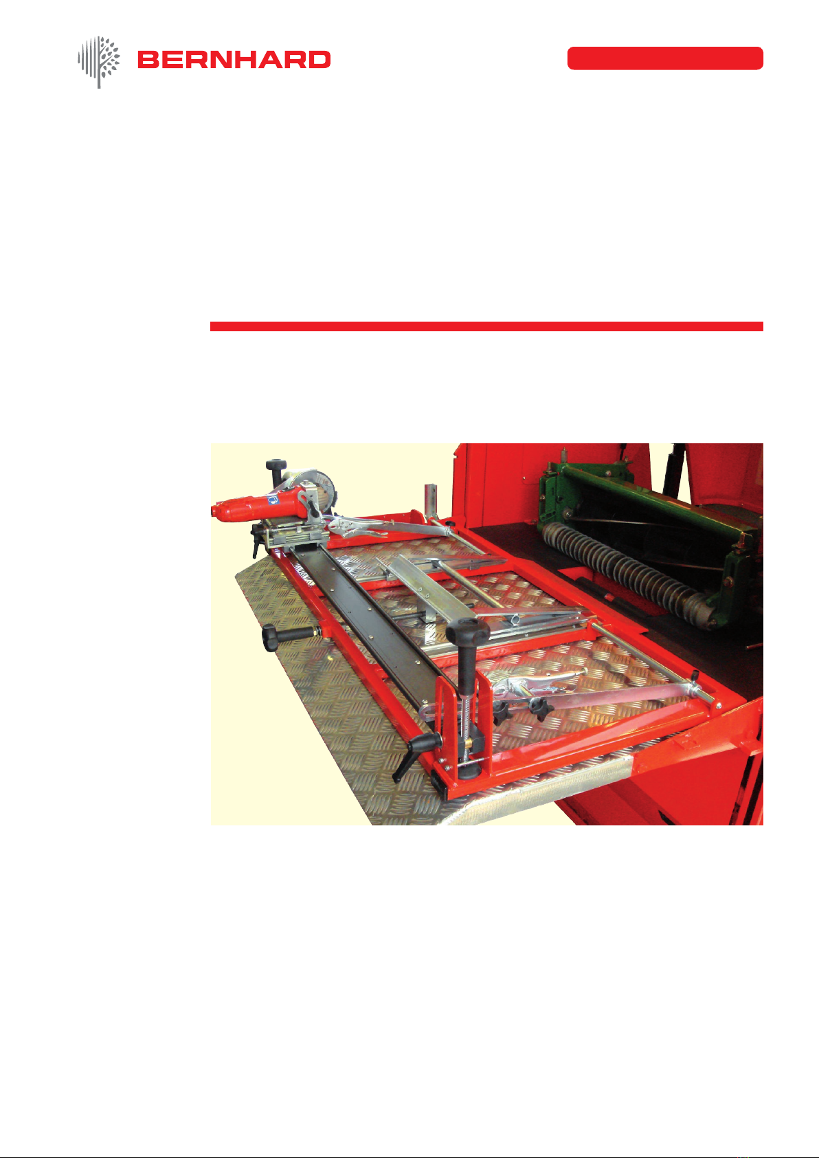
EXPRESS RELIEF
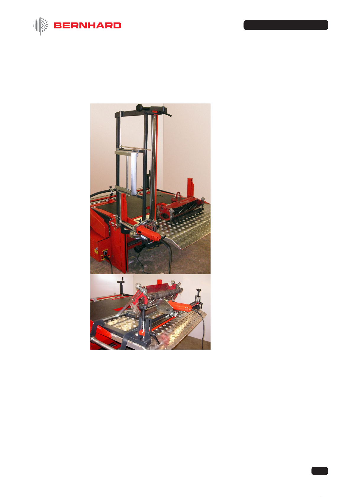
in Up position
EXPRESS RELIEF
in Down position

4
EXPRESS RELIEF
© Bernhard and Company Limited
1.1 This machine is designed and manufactured ONLY for single blade grinding of lawn mower
reels and MUST NOT be used for any other purpose.
1.2 This machine should be installed, operated and maintained by competent personnel who
have received adequate training.
1.3 Before carrying out any work on the machine, other than grinding, ALWAYS SWITCH OFF
the main electrical supply, or remove the power lead from its socket.
1.4 NOISE - Owing to the widely varying conditions of use, noise emissions may vary
considerably. There may be occasions when the safe noise level may be exceeded (see
note on noise emission). In this case adequate ear protection MUST be worn.
1.5 NEVER t or use a grinding wheel (or other spares) other than those supplied specically
for use on the EXPRESS RELIEF (Warranty will be invalidated).
1.6 NEVER t or use a grinding wheel which has been dropped or subjected to any other form
of abuse.
NOTE: Grinding wheels should be tted O NLY by competent, trained personnel.
1.7 NEVER leave rags or tools on the machine or wear any loose clothing or other articles
which could be caught in moving components.
1.8 NEVER allow any combustible materials to be placed on or around the machine.
1.9 ALWAYS ensure that all parts of the cutting unit being ground are securely xed.
1.10 ALWAYS ensure that all electrical connections are sound and all cables are safely routed.
1.11 STAY ALERT. Watch what you are doing. NEVER operate the machine when tired, or
under the inuence of drugs or alcohol.
If the machine is raised to the UP position, ALWAYS secure it with the safety locking pin.
1. Safety
5
EXPRESS RELIEF
© Bernhard and Company Limited
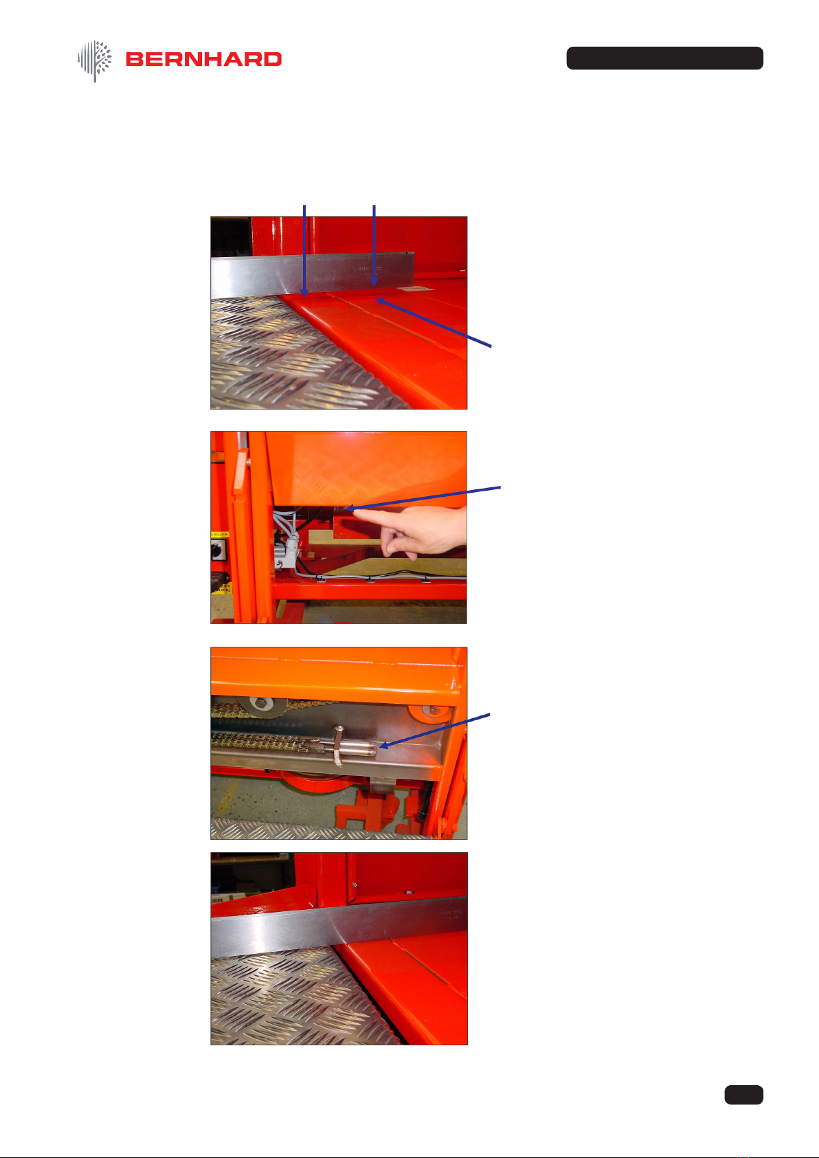
2.1 Check the height of the lift table platform – relative to the machine table.
If it is higher, as shown left, it will need to
be adjusted.
2 . 2 Undo the two wing knobs and remove the
cover from the lft table mechanism.
2.3 Using an ‘allen’ key in the adjusters, adjust
the chain length so that the platform and
the machine table are level.
2. Installation

6
EXPRESS RELIEF
© Bernhard and Company Limited
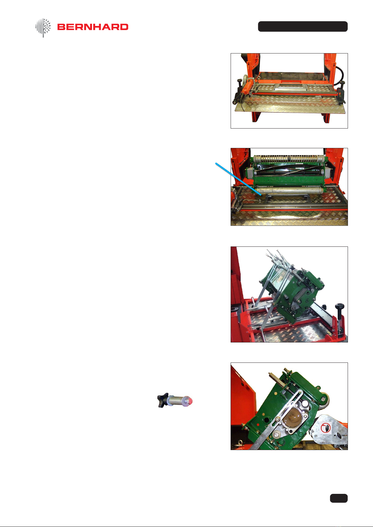
2.4 If necessary assemble the support/pivot
shaft to the Express Relief chassis.
Locate the chassis over the shaft as
shown, with the end of the shaft ush with
the outer chassis boss.
Position the two adjustable collars
as shown and secure in position with
the grub screws, to prevent lateral
movement of the chassis on the support/
pivot shaft.
2.5 Place the Express Relief on the lift table platform as shown (ensure that the bolts securing
the support/pivot shaft to the bracket go into the detents in the shaft).
2.6 Position the support bracket so that
it is central on the side plate of the
lift table chassis.
2.7 Mark the hole positions, using the
support bracket as a template.
Drill 8.5mm & Tap M10 (using the
drill and tap supplied).
Securely bolt the Express Relief to
the machine.

7
EXPRESS RELIEF
© Bernhard and Company Limited
These instructions assume that the Express Relief has been correctly tted to the lift table
of an Express Dual according to the supplied tting instructions.
3.1 If the Express Relief is in its "lowered"
position, supported on the lift table
platform, lower the lift table platform to the
ground.
3.2 Slide the grinding head the left hand side of the guide
rail and pivot the Express Relief about its mounting, to the
vertical position and hold in position with the locking pin.
3.3 Place the cutting unit on the lift table, front facing away from the machine and raise the
platform so that the cutting unit can be slide onto the machine table.
3. User Instructions
8
EXPRESS RELIEF
© Bernhard and Company Limited
3.5 Bring the cutting unit onto the Express
Relief so that it’s rear roller is located in the
‘V’ support.
3.6 Position the adjustable clamps in the
slotted side supports so that they can
be attached to an appropriate (solid and
secure) part of the mower frame to secure
the cutting unit, starting at an angle of
approximately 45 degrees.
3.7 Alternatively, secure with a suitable bolt
directly through the side supports to the
cutting unit or (if necessary, use the spacer
bosses provided).
3.4 Lower the lift platform around 4” (100mm),
remove the locking pin and lower the
Express Relief to the horizontal position.
Raise the platform to it’s highest position
once more to support the Express Relief
frame.
9
EXPRESS RELIEF
© Bernhard and Company Limited
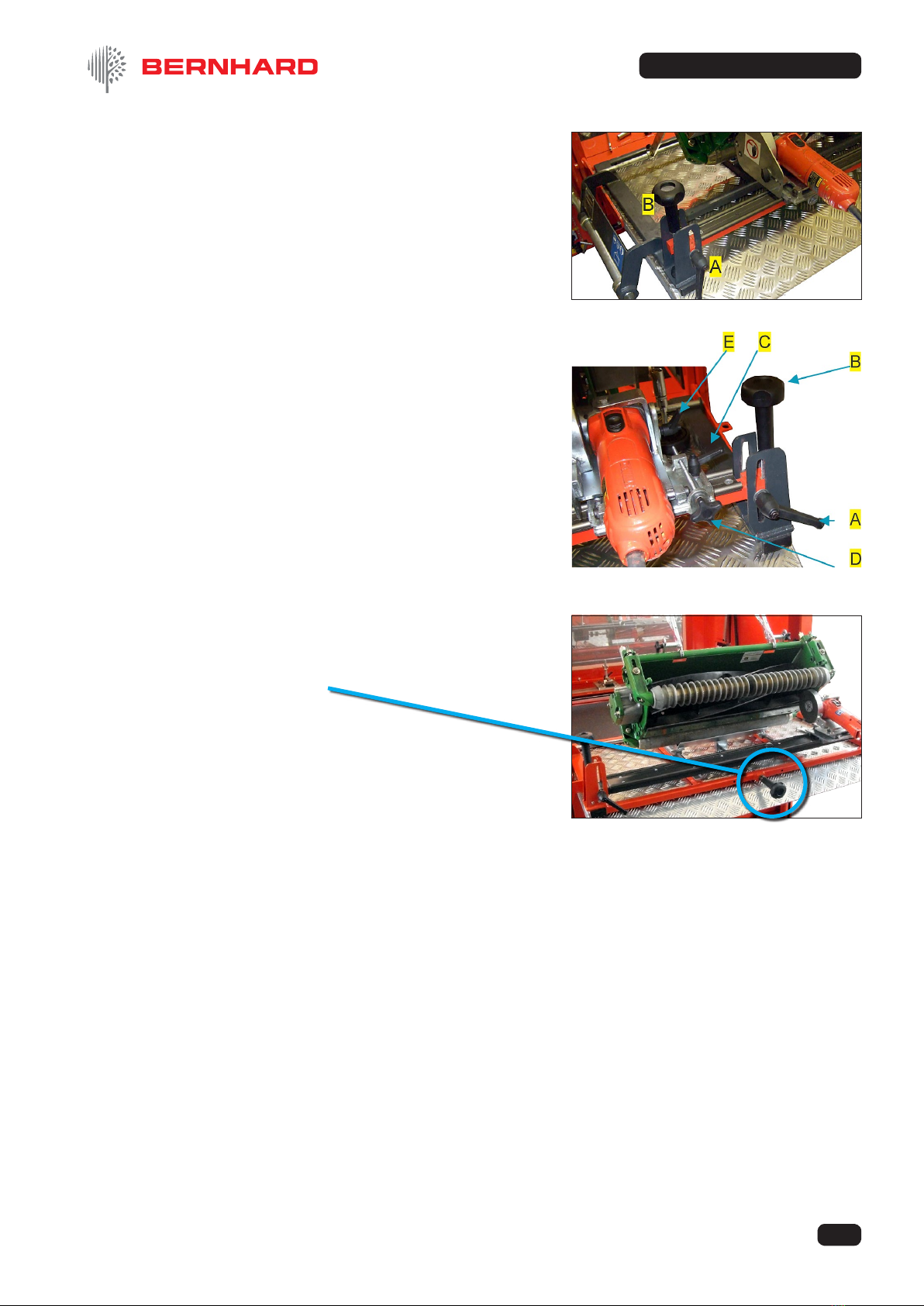
3.9 Loosen locking lever [C] to enable
horizontal infeed of the grinding head
using handwheel [D], Loosen locking lever
[E] to enable angular adjustment of the
grinding head.
3.8 Loosen locking levers [A] and raise
the guide rail by rotating adjusters
[B] at each end of the rail, for coarse
positioning of the grinding head relative
to the cutting unit.
3.10 Fine adjustment of mower position back
and forth can be achieved by moving the
vee support for the rear roller with the
handwheel.
10
EXPRESS RELIEF
© Bernhard and Company Limited
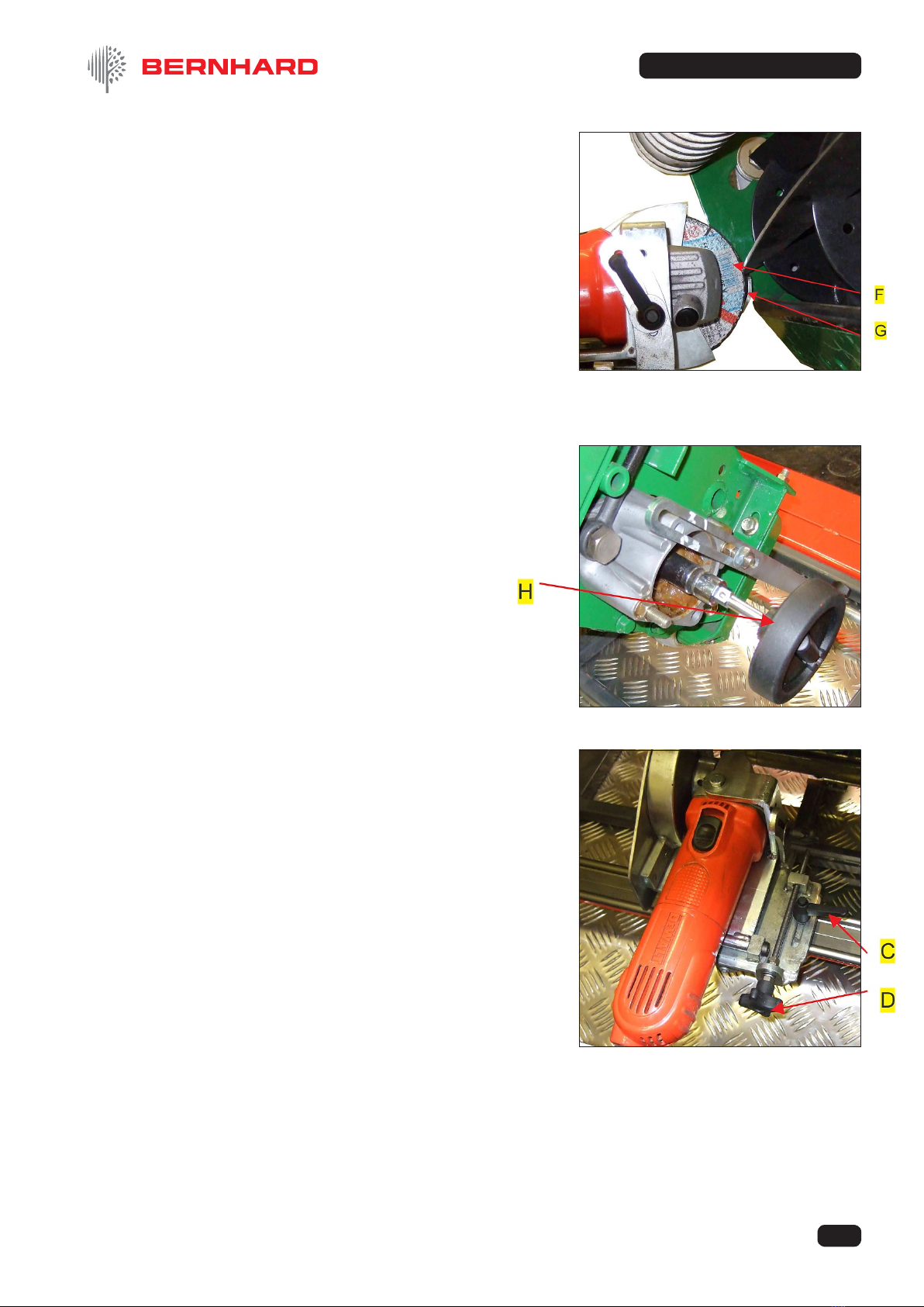
3.9 Position the grinder so that a reel blade can
be “trapped” between grinding disc [F] and
support nger [G] with the grinding disc
setting the required angle of relief to the blade.
Using the adjusting handwheels [B] at each
end of the guide rail, make ne adjustments
until contact between reel blade and grinding
disc is even along the length of the blade.
Lock this position using levers [A].
Note: Fine adjustments can later be repeated like
(with the grinder running) this to ensure an
equal width of land ground along the reel
blade.
3.10 With a suitable driver attached, insert the
reel control handwheel [H] into the cutting
unit so that each reel blade can be safely
held against the support nger and to allow
indexing from blade to blade.
3.11 Move the grinder to one end of the reel, back
the disc away from the reel blade slightly
using feed knob [D], switch on the grinder.
Feed the grinder in to apply a reasonable cut
and tighten feed locking lever [C].
3.12 Traverse the grinder back and forth along each reel blade, increasing cut as necessary,
until an acceptable amount of relief (blade thinning) has been applied.
Note: Ideally mark the rst blade that is ground, grind each blade in turn for one complete
revolution of the reel, then apply a ne nishing cut and repeat grinding for one revolution
of the reel in the opposite direction.
11
EXPRESS RELIEF
© Bernhard and Company Limited
4. Parts List
Page
EXPRESS RELIEF COMPLETE ____________________________ 11
EXPRESS RELIEF FRAME ASSEMBLY _____________________ 12
FRONT RAIL ASSEMBLY _________________________________ 13
GRINDER TROLLEY ASSEMBLY __________________________ 14
HINGE ASSEMBLY ______________________________________ 15
RIGHT HAND MOWER SUPPORT ASSEMBLY _______________ 16
LEFT HAND MOWER SUPPORT ASSEMBLY ________________ 17
Ref # Name of Part Qty. Part #
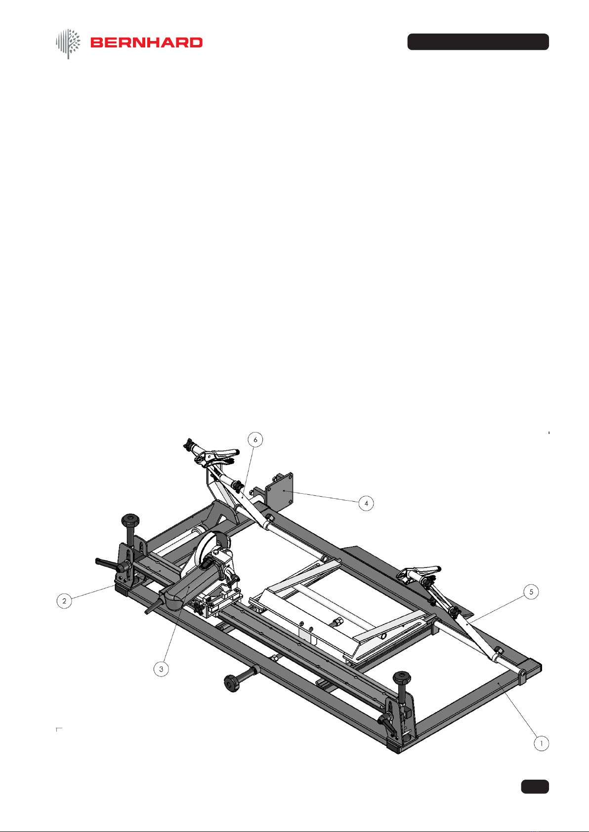
EXPRESS RELIEF COMPLETE ________________________________
1 Express Relief Frame Assembly.............................................1 03938
2 Front Rail Assembly ................................................................1 03935
3 Grinder Trolley Assembly........................................................ 1 03714
4 Hinge Assembly ...................................................................... 1 03939
5 RH Mower Support Assembly.................................................1 03940
6 LH Mower Support Assembly ................................................. 1 03941
12
EXPRESS RELIEF
© Bernhard and Company Limited
4. Parts List (Continued)
Ref # Name of Part Qty. Part #
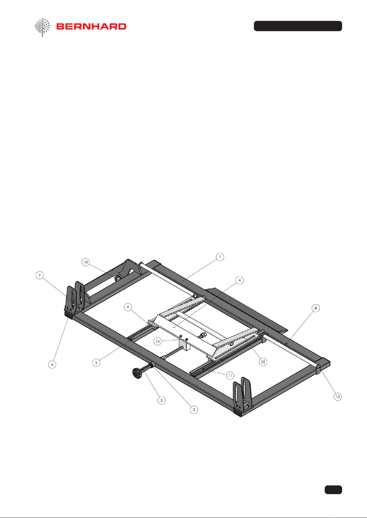
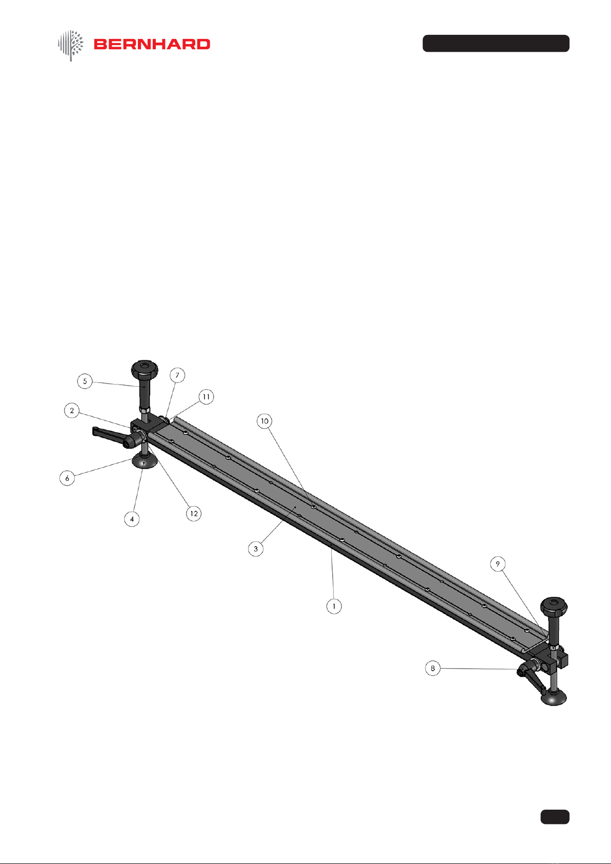
EXPRESS RELIEF FRAME ASSEMBLY _________________________
1 Main Frame Fabrication .......................................................... 1 03934
2 Feed Screw Bush .................................................................... 1 03718
3 Single Slide Rail ......................................................................2 03422
4 BT Roller Cradle......................................................................1 04154
5 Roller Cradle Feed Assembly ................................................. 1 03717
6 Plastic Cap For Side Arm........................................................ 4 06151
7 M5 x 70 Cap Head Socket Bolt ............................................... 4 05200
8 Rear Shaft ............................................................................... 2 03363
9 DryLin Bearing ........................................................................ 4 03346
10 Oilite Bush 1 1/4” Bore ............................................................2 07701
11 ISO 7380 - M5 x 12 --- 12N..................................................... 8
12 ISO 7380 - M8 x 25 --- 25N.....................................................2
13 ISO 10642 - M6 x 16 --- 16N...................................................2
14 Hexagon Nut ISO - 4034 - M5 - N...........................................4
15 ISO 7380 - M5 x 20 --- 20N ....................................................4
13
EXPRESS RELIEF
© Bernhard and Company Limited
4. Parts List (Continued)
Ref # Name of Part Qty. Part #
FRONT RAIL ASSEMBLY _____________________________________
1 Main Rail Fabrication .............................................................. 1 03715
2 Mounting Bar Pivot Boss.........................................................2 03360
3 Wide Igus Rail .........................................................................1 03703
4 Self Aliening Foot .................................................................... 2 06147
5 4 Lobe Knob 50mm................................................................. 2 06135
6 Nylon Spacer........................................................................... 2 03511
7 M10 Double coil spinng M10 Double coil spring ..................... 2
8 Kip Lever M10x30.................................................................... 2 0 6119
9 Hexagon Nut ISO - 4032 - M12 - D - N ................................... 2
10 ISO 7380 - M5 x 12 --- 12N................................................... 11
11 ISO 7380 - M10 x 30 --- 30N................................................... 2
14
EXPRESS RELIEF
© Bernhard and Company Limited
4. Parts List (Continued)
Ref # Name of Part Qty. Part #
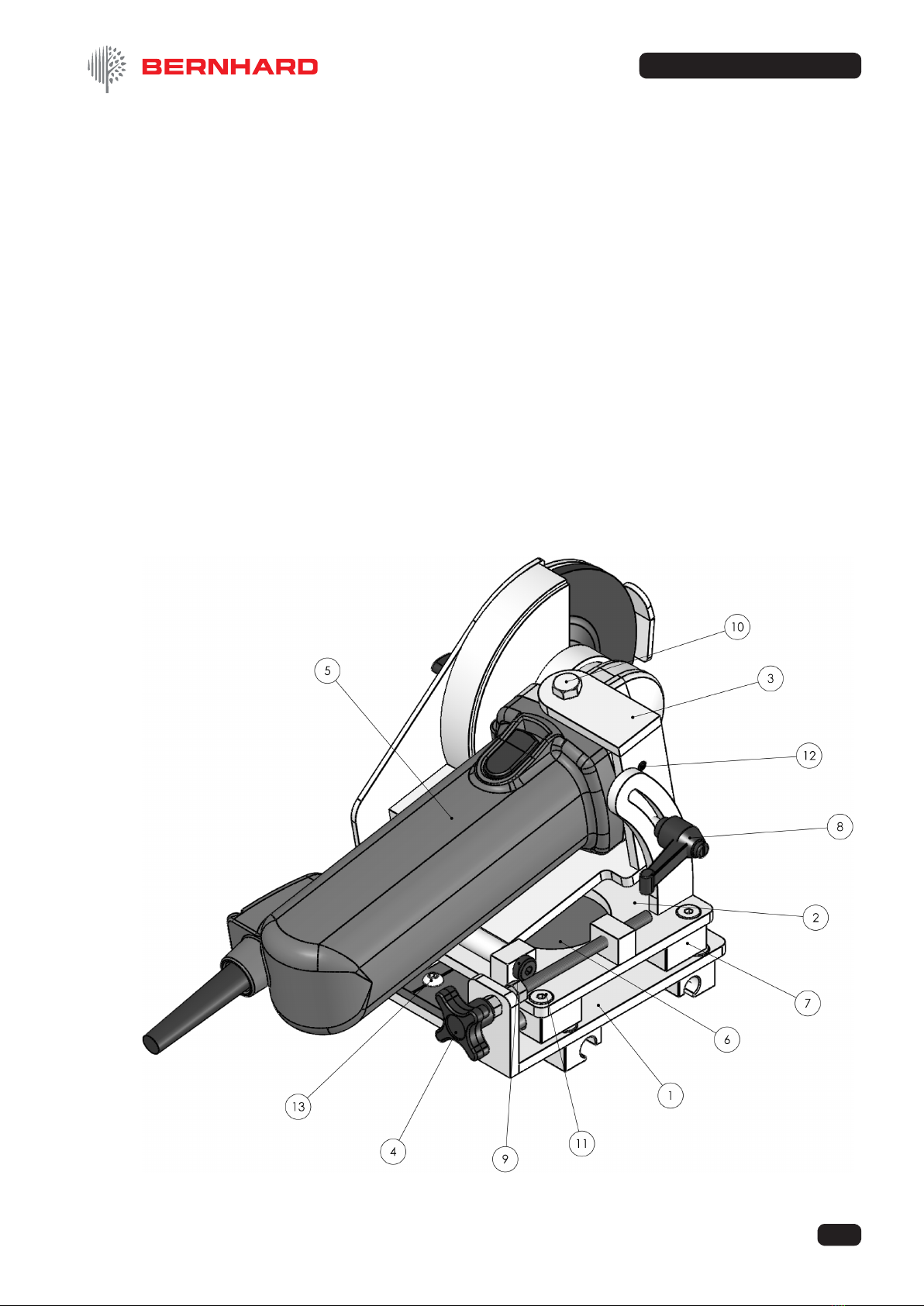
GRINDER TROLLEY ASSEMBLY ______________________________
1 Base Carriage Fabrication ......................................................1 03711
2 Grinder Slide Carrage Fabrication ..........................................1 03709
3 Grinder Pivot Bracket Fabrication..........................................1 03706
4 Feed Screw Assembly ............................................................ 1 03379
5 Grinder Complete With Guard ................................................ 1 03374
6 Igus Cross Slide ...................................................................... 1 03713
7 DryLin Bearing ........................................................................ 8 03346
8 M6 x 16 Kip Lever F ................................................................ 1 06128
9 Shoulder Screw M8x12 ........................................................... 2 05165
10 ISO 4018 - M8 x 16-WN .......................................................... 2
11 ISO 10642 - M6 x 16 - -- 16N .................................................. 8
12 BS 4168-5 - M6 x 8-N ............................................................. 2
13 ISO 7380 - M6 x 12 --- 12N..................................................... 4

15
EXPRESS RELIEF
© Bernhard and Company Limited
4. Parts List (Continued)
Ref # Name of Part Qty. Part #
HINGE ASSEMBLY __________________________________________
1 Hinge Support Fabrication ......................................................1 03378
2 Hinge Fabrication .................................................................... 1 03377
3 T Pin ........................................................................................ 1 04262
4 1 1/4” Set Collar....................................................................... 2 04050-14
5 BS 4168-5 - M10 x 10-N.......................................................... 2
6 ISO 4018 - M8 x 30-WN..........................................................2
16
EXPRESS RELIEF
© Bernhard and Company Limited
4. Parts List (Continued)
Ref # Name of Part Qty. Part #
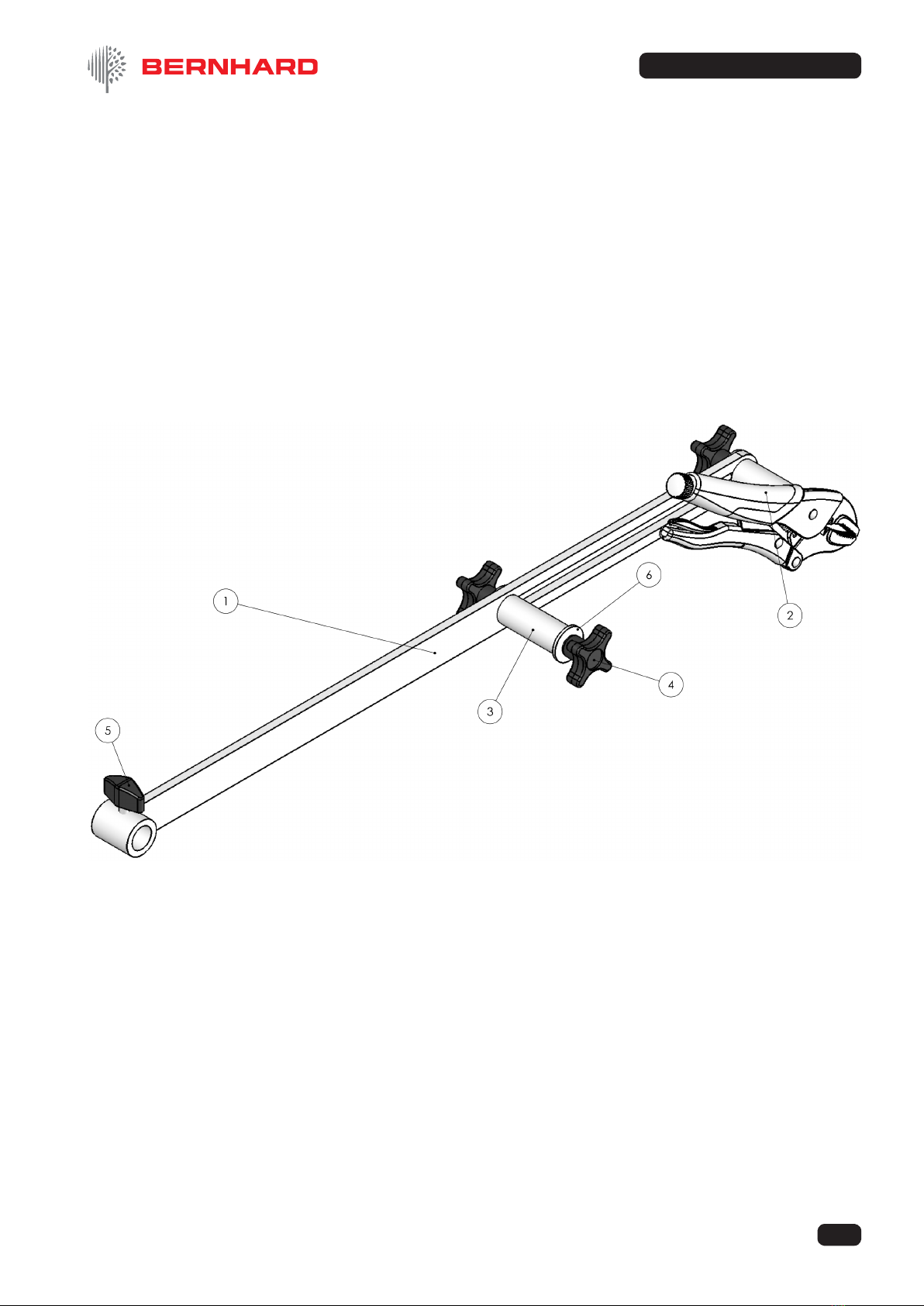
RIGHT HAND MOWER SUPPORT ASSEMBLY ___________________
1 Mower Support Stay Complete ............................................... 1 03369
2 LH Vice Grip Clamp Fabrication ............................................. 1 03727
3 Support Stay Spacer ...............................................................1 03366
4 M8 x 15mm Lobe Knob ........................................................... 3 06131
5 Wing Knob M6x10 ................................................................... 1 06126
6 Black washer BS 4320 - M8 (Form G) .................................... 3
17
EXPRESS RELIEF
© Bernhard and Company Limited
4. Parts List (Continued)
Ref # Name of Part Qty. Part #
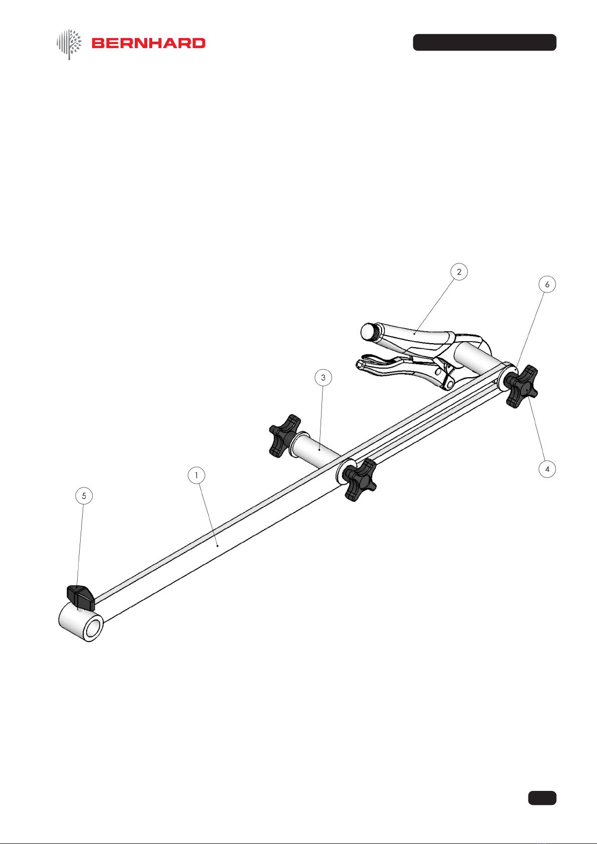
LEFT HAND MOWER SUPPORT ASSEMBLY ____________________
1 Mower Support Stay Complete ............................................... 1 03369
2 RH Vice Grip Clamp Fabrication............................................. 1 03726
3 Support Stay Spacer ...............................................................1 03366
4 M8 x 15mm Lobe Knob ........................................................... 3 06131
5 Wing Knob M6x10 ................................................................... 1 06126
6 Black washer BS 4320 - M8 (Form G) ................................... 3

BERNHARD & CO. LIMITED
Bilton Road • Rugby • England • CV22 7DT
Tel +44 1788 811600 • Fax +44 1788 812640
Email: [email protected]
USA Toll Free 1-888 GRIND IT (1-888 474 6348)
If you have any service or operational issues please contact your distributor
or phone our technical support hotline
Technical Helpline (USA only) 1-888 474 6348
Rest of World: UK Head Ofce, England (+44) 1788 811600
Email: techsupport@bernhard.co.uk
Technical FAQs can be found on our web site: www.bernhard.co.uk
When ordering spare parts please quote the machine type and serial number.
THE MANUFACTURERS ACCEPT NO RESPONSIBILITY FOR ANY SITUATION ARISING FROM
THE FITTING AND/OR USE OF NON-ORIGINAL SPARE PARTS.
Table of contents
Other Bernhard Lifting System manuals

Popular Lifting System manuals by other brands


Nussbaum
Nussbaum JUMBO NT 3500 Operating Instruction and Documentation

probst
probst AKZ-UNI-H operating instructions

Vestil
Vestil HDC-305 Series manual

Nuvo
Nuvo Navigator Lift 180 Single operating instructions

North American Ramps
North American Ramps CHECK OUT ProMaster MANUAL & SAFETY INSTRUCTIONS

Basta Boatlifts
Basta Boatlifts Over-Center 36k60 Assembly and installation instruction


