manuals.online logo
Brands
  1. Home
  2. •
  3. Brands
  4. •
  5. Basta Boatlifts
  6. •
  7. Lifting System
  8. •
  9. Basta Boatlifts Over-Center 36k60 User manual

Basta Boatlifts Over-Center 36k60 User manual

tm
Over-Center Hydraulic Steel Lift
36,000 lbs Capacity
READ complete manual CAREFULLY
BEFORE attempting assembly or operation
ASSEMBLY
INSTALLATION
3/23
Copyright 2023 Basta Inc
©
866-GO-BASTA
www.gobasta.com
Basta Inc. Seatac WA 98198 USA L392-0111B
36k60
(16,300 kg Capacity) Model # 36k60
page 2
For a full list of patents, go to:
bastaboatlifts.com/patents
DANGER
• Do not exceed the maximum weight capacity specified for the lift. Maximum weight capacity
can be found on the cover of this manual and on the H frame of the lift.
Improper use or failure to follow this instruction can cause property damage, serious injury,
or death.
• Never use for lifting humans or animals. Improper use or failure to follow this instruction can
cause property damage, serious injury, or death. The lift should only be used for lifting boats
& watercraft.
• Always avoid being under, and maintain adequate clearance from, the lift. Failure to follow
this instruction can cause serious injury or death.
• Always use AGM batteries and follow battery manufacturer's warnings and instructions.
Improper use, or use of other batteries, have the potential to produce flammable hydrogen
gas which can result in serious injury or death.
WARNING
• Visually inspect all parts and assemblies for damage or defects prior to assembling lift.
• Install the lift on firm and level ground.
• Verify the lower frame of the lift is level before each use.
• Do not play on or near the lift.
• Do not service the unit with the watercraft on the lift.
• High pressure hydraulics can penetrate skin. Oil injected into the skin from high pressure
systems can cause severe injury. In the case of injury, seek medical attention immediately.
CAUTION
• Do not install the lift alone.
• The lift should only be used for lifting boats & watercraft.
• Passengers should stand clear of the lift when the lift is in operation.
Assembly Instructions ...........................................................................Pages 8 - 21
First Use / Adjustments
..………….…...........................................................Page 23
Operating Instructions ....……..........................……………....…………..…...Page 24
Parts Assembly Diagram....................................................................Pages 4 - 7, 22
Maintenance Guide/ Log.…..................................................................Pages 25 - 26
TABLE OF CONTENTS
Warning ..……………………..................................................................................Page 2
Warranty.............................….............................................................................Page 28
page 3
PRODUCT INFORMATION
Model #:
Serial #:
Purchased From:
Date of Purchase:
Contact Name:
Phone #:
Notes:
IMPORTANT!
WARRANTY MUST BE
REGISTERED WITHIN 30 DAYS
OF INSTALLATION.
TO REGISTER, SCAN HERE OR VISIT
WWW.BASTABOATLIFTS.COM/SUPPORT
Troubleshooting / FAQ .…............................................................................Page 27
page 4
In the following pages various symbols are used:
indicates an illustration for a procedure.
indicates a major part shown and described above.
indicates a hardware item shown and described on pages 6-7.
12
1
C3
1
1
2
3
4
5
6
7
7
8
10
12
13
17
18
9
5
18
18
1
1
14
14
10
10
14
11
15
16
19
20
23
24
25
PARTS LIST - DIAGRAM
10
10
21
22x60
PARTS LIST
FOR QUESTIONS ABOUT PARTS PLEASE CALL BASTA BOATLIFTS AT
(425) 641-8911
ITEM PART # DESCRIPTION
1Base Crossmember
W110-0032
QTY
4
2
3
4
5
6
7
8
9
10
11
12
13
14
15
16
17
18
19
20
21
22
Left Side Rail
Right Side Rail
H-Frame, Aft
H-Frame, Center
H-Frame, Forward
Bunk Rail
Adjustable Support Leg
Leg Cap
Bunk Chevron, Forward
Bunk Chevron, Mid
Bunk Chevron, Aft
Foot Pad
Bunk Board Assembly, Forward
Bunk Board Assembly, Aft
Guide Board
Keel Block
Dual Hydraulic Cylinder Kit
Load Guide Stanchion
Guide Board Assembly, Upper
Bunk Stanchion*
Bunk Stanchion Backing Plate*
W104-0038
W104-0039
W101-0071
W101-0070
W101-0069
W113-0039
K200-0223
F730-0013
W113-0029
W113-0031
W113-0030
W116-0010
A428-0043
A428-0044
W410-0097
W410-0081
H310-0024
W108-0046
A428-0045
K204-0116
K204-0160
1
1
1
1
1
2
8
8
4
1
1
8
6
2
2
4
3
2+
4
60
60
23
24
25
CG Bolt Plate
CG Socket Weldment
CG Buffer Tube
K204-1095
W108-0047
K204-1125
var.
var.
var.
26 Keel Block Spacer**W410-0081 var.
*shown on next page
** not shown
page 5
page 6
M
I
H
G
F
G
H
M
F
KL
K
N
E
N
F
H
I
F
H
PRE-INSTALLED
(ALL BUNKS)
J
B
D
A
B
CC
B
M
HARDWARE - DIAGRAM
ITEM PART # DESCRIPTION
A1 5/8” x 1-1/2” hex head set screw, SSS166-6812
QTY
48
B1
B2
B3
C1
C2
C3
D1
D2
D3
E1
E2
F1
F2
F3
G1
G2
G3
H1
H2
1/2” x 1-1/2” hex head cap screw, SS
1/2” flat washer, SS
1/2” nylon insert lock nut, SS
1” x 9” hex head cap screw, SS
1” flat washer, SS
1” nylon insert lock nut, SS
3/4” x 5” hex head cap screw, SS
3/4” flat washer, SS
3/4” nylon insert lock nut, SS
ring type cotter pin, SS
3/4” x 3-1/2” clevis pin, SS
1/2” x 4” hex head cap screw, SS
1/2” flat washer, SS
1/2” nylon insert lock nut, SS
1/2” x 1-1/2” hex head cap screw, SS
1/2” flat washer, SS
1/2” nylon insert lock nut, SS
1/2” x 4” hex head cap screw, SS
1/2” flat washer, SS
S103-0707
S313-0010
S362-0010
S103-1020
S313-4015
S362-0014
S103-0912
S313-0013
S362-0012
S522-0801
S503-0013
S103-0717
S313-0010
S362-0010
S103-0707
S313-0010
S362-0010
S103-0717
S313-0010
32
64
32
8
8
8
8
8
8
12
12
24
48
24
36
72
36
72
144
H3 1/2” nylon insert lock nut, SS
S362-0010 72
HARDWARE
*Centering device (CD) hardware not pictured
I1
I2
I3
J1
J2
J3
K1
K2
5/16” flat washer, galvanized
5/16” lock washer, galvanized
5/16” hex nut, galvanized
1/2” x 1-1/2” hex head cap screw, SS
5/16” flat washer, galvanized
5/16” lock washer, galvanized
5/16” hex nut, galvanized
5/16” flat washer, galvanized
S321-0007
S321-0007
S341-0007
S341-0007
S103-0707
S312-0007
S321-0007
S341-0007
S312-0007
S312-0007
8
8
8
16
16
120
16
120
24
120
L2
L3
M1
N1
N2
N3
1/2” flat washer, SS
1/2” nylon insert lock nut, SS
1/2” flat washer, SS
1/2” nylon insert lock nut, SS
5/8” x 1-1/2” hex head set screw, SS
1/2” x 5” hex head cap screw, SS
S362-0010
S313-0010
S362-0010
S166-6812
S103-0719
S313-0010
48
24
24
48
96
48
K3
L1
ITEM PART # DESCRIPTION QTY
21
22
Bunk Stanchion Backing Plate
bolt plate, 3.25” x 6”K204-0160
K204-0116 60
60
AM
B
C
D
GL
IJK
F H
N
E
Note: Items A-N referred to as sets
(i.e., C = bolt, washer, nut)
HARDWARE - LIST
21
22
page 7
ASSEMBLY INSTRUCTIONS
Foot and Leg Sockets (8 Total)
1
QTY SIZE TYPE
hex head set screws5/8 x 1-1/2
REF
A1
apply a small
amount of grease
to bolt threads
HARDWARE
2
1
1
1
1
1
2
3
3
2
2
tighten leg set screws
alternately to push the
leg securely into the
corner of the leg socket
page 8
step
1
?parts identified
on page 4
A1
A1
A1
8
13 A1
1
22
1
1
48
Aft & Center Crossmembers Forward Crossmember
2
3
QTY QTYSIZE SIZETYPE TYPE
bolts 1/2 x 1-1/2
1/2
1/2
REF REF
B2B2
B3B3
B1B1 bolts
flat washersflat washers
lock nutslock nuts
apply a small
amount of grease
to bolt threads
apply a small
amount of grease
to bolt threads
HARDWARE
HARDWARE
do not tighten these bolts
completely until the H-frames
and bunks have been
installed & squared up
do not tighten these bolts
completely until the H-frames
and bunks have been
installed & squared up
page 9
step
?parts identified
on page 4
?parts identified
on page 4
B2 B3
B1 B2
B2 B3
1
B1 B2
B1 B2
B1 B2
1
2
2
1
16
8
8
48
24
24
1/2 x 1-1/2
1/2
1/2
ASSEMBLY INSTRUCTIONS
page 10
Forward H-Frame
QTY SIZE TYPE
bolts1 x 9
REF
C1
flat washers
lock nuts
1
1
C2
C3
4apply a small
amount of grease
to bolt threads
HARDWARE
step
?parts identified
on page 4
6
FORWARD CENTER AFT
C2 C3
C1
6
X2
5
5
4
2
2
2
Center H-Frame (2 total) Aft H-Frame
QTY QTYSIZE SIZETYPE TYPEREF REF
6
5
apply a small
amount of grease
to bolt threads
apply a small
amount of grease
to bolt threads
HARDWARE
HARDWARE
bolts bolts1 x 9 1 x 9C1 C1
flat washers flat washers
lock nuts lock nuts
1 1
1 1
C2 C2
C3 C3
page 11
step
step
FORWARD CENTER AFT
?parts identified
on page 4
?parts identified
on page 4
FORWARD CENTER AFT
C1
C3
C2
C1
C2 C3
C1
C2 C3
5
4
AFT
X2
X2
4
4
4
2
2
2
9
8
ASSEMBLY INSTRUCTIONS
Bunk Rails
QTY SIZE TYPE
bolts3/4 x 5
REF
D1
flat washers
lock nuts
3/4
3/4
D2
D3
7apply a small
amount of grease
to bolt threads
HARDWARE
tighten these nuts only
“finger tight” until the
cylinders are installed
page 12
step
?parts identified
on page 4
D1 D2 D3
7
7
7
7
7
8
7
7
7
7
8
8
9
8
8
8
Forward + Mid Hydraulic Cylinders Aft Hydraulic Cyinders
QTY QTYSIZE SIZETYPE TYPE
ring type cotter pinsring type cotter pins
clevis pinsclevis pins
3/32 x 23/32 x 2
3/4 X 53/4 X 5
REF REF
E2E2
E1E1
9HARDWARE
HARDWARE
install the clevis pins
“E2” with their heads
toward the inside of the lift
page 13
step
NOTICE
tighten the bunk rail nuts and
crossmember bolts after
all the cylinders are installed
?parts identified
on page 4
?parts identified
on page 4
INSIDE
INSIDE
E1
E2
INSIDE
INSIDE
E1
E2
18
6
E2 E1
5
18
8
step
NOTE: Install cylinders with lift in
'down' position
8
8
4
4
F2 F3 F2 F3
F1
F2
F1
F2
1”
2.54cm
Bunk Chevrons FWD (4 total)
QTY SIZE TYPE
bolts1/2 x 4
REF
F1
flat washers
lock nuts
1/2
1/2
F2
F3
10 apply a small
amount of grease
to bolt threads
HARDWARE
leave bolts loose
until bunk boards
are installed
page 14
step
?parts identified
on page 4
10
78”
198cm
78”
198cm
78”
198cm
42.5”
108cm
35.5”
90cm
approximate starting locations
10
12
11
10
FWD (X4)
AFT (X1)
MID-AFT (X1)
10
10
10
12
11
ASSEMBLY INSTRUCTIONS
16
32
16
F2F3
F1
F2
F2 F3
F1
F2
Bunk Chevrons Mid-AftBunk Chevrons Aft
12
11
page 15
step
step
F2 F3
F1 F2
F1
F2
F2F3
11
12
QTY SIZE TYPE
bolts1/2 x 4
REF
F1
flat washers
lock nuts
1/2
1/2
F2
F3
apply a small
amount of grease
to bolt threads
HARDWARE
QTY SIZE TYPE
bolts1/2 x 4
REF
F1
flat washers
lock nuts
1/2
1/2
F2
F3
apply a small
amount of grease
to bolt threads
HARDWARE
?parts identified
on page 4
leave bolts loose
until bunk boards
are installed
STEP 11: MID-AFT, BRACKET MUST FACE FORWARD
STEP 12: AFT, BRACKET MUST FACE AFT
4
8
4
4
8
4
16
15
13
16
18
18
14
14
ASSEMBLY INSTRUCTIONS
REF
I1
I2
I3
galvanized lock washers
I2
I3 I1
galvanized flat washers
FORWARD
galvanized hex nut
TYPE
16
Guide Board (2 total)
Brackets
SIZE
5/16
5/16
5/16
11
QTY
step HARDWARE
12
13 apply a small
amount of grease
to bolt threads
?parts identified
on page 4
page 16
8
8
8
the bunks may have to be adjusted
several times for the best fit -
page 17
remember to tighten all the
bolts installed in Step 10
NOTICE
WITHOUT BOAT ON LIFT!
?parts identified
on page 4
14 apply a small
amount of grease
to bolt threads
J2
J1
J3
HARDWARE
step
QTY
Keel Board (3 Total)
SIZE
5/16
5/16
5/16
galvanized flat washers
galvanized lock washers
galvanized nuts
10
TYPE
17
REF
J1
J2
J3
Bunks AFT (2 total)
15
step
21
15
15
12
11
10
H1 H2H2H3
22
QTY SIZE TYPE
bolts
flat washers
lock nuts
1/2 x 4
1/2
1/2
REF
G2, H2
G3, H3
H1
apply a small
amount of grease
to bolt threads
HARDWARE
?parts identified
on page 4
bolts1/2 x 1-1/2 G1
FORWARD
16
16
16
72
36
24
12
page 18
Bunks FWD (6 total)
QTY SIZE TYPE
bolts
flat washers
lock nuts
1/2 x 4
1/2
1/2
REF
G2, H2
G3, H3
H1
16 apply a small
amount of grease
to bolt threads
HARDWARE
step
?parts identified
on page 4
21
H2
H1H3
H2
21
22
14
10
10
bolts1/2 x 1-1/2 G1
FORWARD
48
144
72
24
G1
G1
18
step
L2
L3
L1
L2
Load Guide Stanchions
17
step
19
12
QTY SIZE TYPE
hex head set screws5/8 x 1-1/2
REF
M1
apply a small
amount of grease
to bolt threads
HARDWARE
?parts identified
on page 4
11
QTY SIZE TYPE
bolts
flat washers
lock nuts
1/2 x 1-1/2
1/2
1/2
REF
L2
L3
apply a small
amount of grease
to bolt threads
HARDWARE
?parts identified
on page 4
L1
20
21
page 19
Load Guide Boards
24
48
24
24
page 20
Guide Board Assembly, UpperCentering Guides (Optional)
20
19
remember to tighten
all the bolts installed
in Step 10
step
step
F2
F3 F1
F2
M1
QTY SIZE TYPE
bolts
flat washers
lock nuts
1/2 x 5
1/2
1/2
REF
N2
N3
N1
apply a small
amount of grease
to bolt threads
HARDWARE
?parts identified
on page 4
20
19
CG mount adjustable
along bunk rail
NOTE: Be sure chosen position does
not make contact throughout cycle
QTY SIZE TYPE
hex head set screws
bolts
flat washers
5/8 x 1-1/2
1/2 x 4
1/2
REF
F1
F2
M1
apply a small
amount of grease
to bolt threads
HARDWARE
?parts identified
on page 4
lock nuts1/2 F3
FORWARD
24
23
19
25
FORWARD
N2
N1
N2
N3
96
48
48
8
16
8
8

Other Basta Boatlifts Lifting System manuals

Basta Boatlifts Over-Center 18k59 User manual

Basta Boatlifts

Basta Boatlifts Over-Center 18k59 User manual

Basta Boatlifts Over-Center 24k60 User manual

Basta Boatlifts

Basta Boatlifts Over-Center 24k60 User manual

Basta Boatlifts Over-Center 12k64 User manual

Basta Boatlifts

Basta Boatlifts Over-Center 12k64 User manual

Basta Boatlifts Over-Center 4.5k37 User manual

Basta Boatlifts

Basta Boatlifts Over-Center 4.5k37 User manual

Basta Boatlifts Over-Center 7k51 User manual

Basta Boatlifts

Basta Boatlifts Over-Center 7k51 User manual

Basta Boatlifts 8k53 User manual

Basta Boatlifts

Basta Boatlifts 8k53 User manual

Basta Boatlifts Over-Center 18k59 User manual

Basta Boatlifts

Basta Boatlifts Over-Center 18k59 User manual

Basta Boatlifts 2x2k50 User manual

Basta Boatlifts

Basta Boatlifts 2x2k50 User manual

Basta Boatlifts Over-Center BM4050SP User manual

Basta Boatlifts

Basta Boatlifts Over-Center BM4050SP User manual

Basta Boatlifts 1.4k60 User manual

Basta Boatlifts

Basta Boatlifts 1.4k60 User manual

Basta Boatlifts Over-Center 10k53 User manual

Basta Boatlifts

Basta Boatlifts Over-Center 10k53 User manual

Basta Boatlifts Over-Center 4.5k37 User manual

Basta Boatlifts

Basta Boatlifts Over-Center 4.5k37 User manual

Basta Boatlifts Over-Center 2k40 User manual

Basta Boatlifts

Basta Boatlifts Over-Center 2k40 User manual

Popular Lifting System manuals by other brands
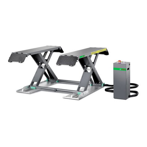
Bosch VLS 3130 Original instructions

Bosch

Bosch VLS 3130 Original instructions

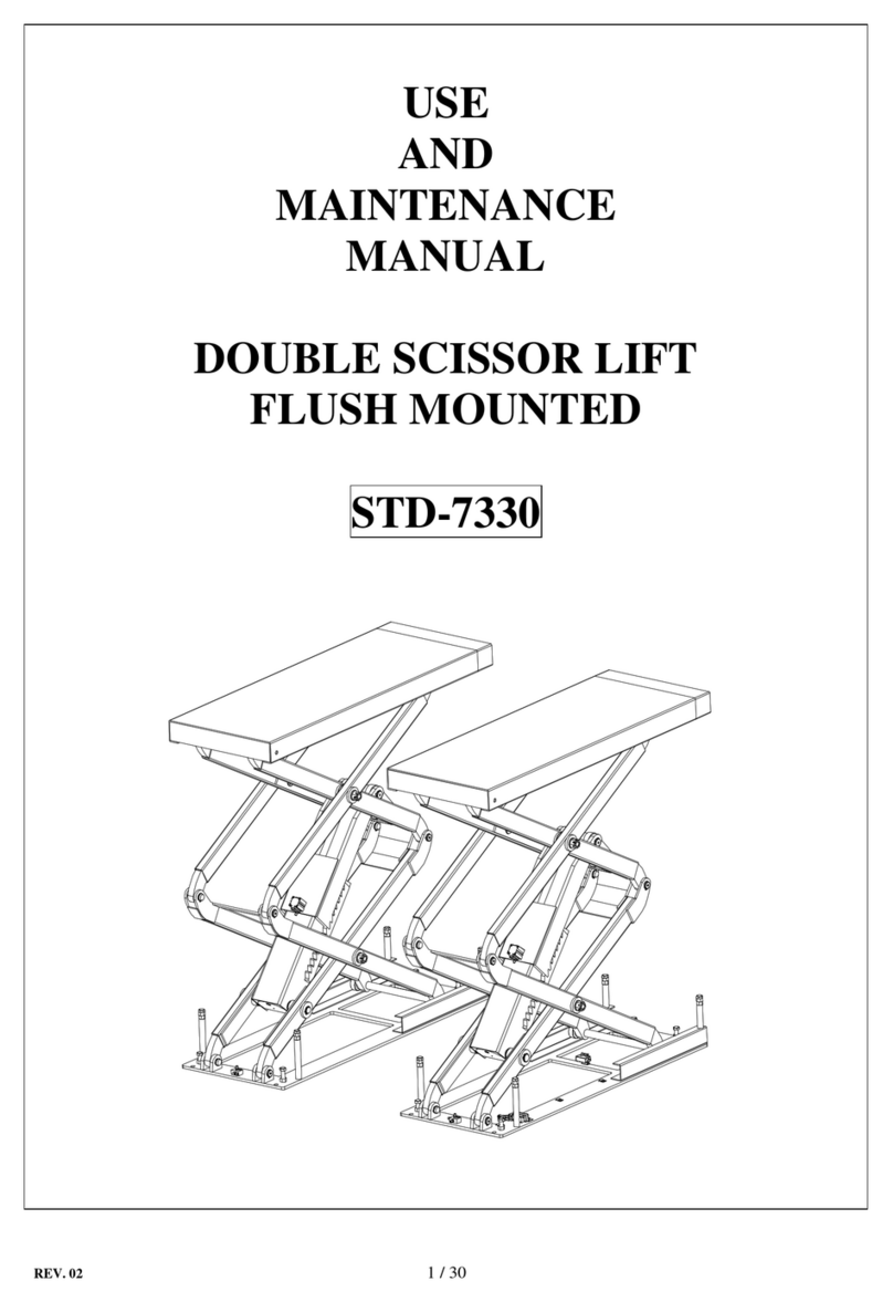
SIVIK STD-7330 Use and maintenance manual

SIVIK

SIVIK STD-7330 Use and maintenance manual

AVL E-Lift II+ Upgrade Installation

AVL

AVL E-Lift II+ Upgrade Installation

Venset TS600B installation instructions

Venset

Venset TS600B installation instructions

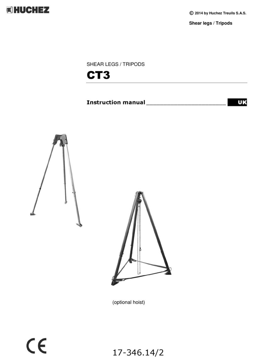
Huchez CT3 instruction manual

Huchez

Huchez CT3 instruction manual

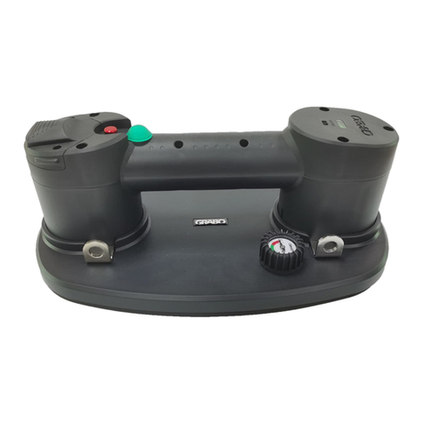
Grabo NEMO Operator's manual

Grabo

Grabo NEMO Operator's manual

Yale Lift-Tech 115325 Operation, service & parts manual

Yale Lift-Tech

Yale Lift-Tech 115325 Operation, service & parts manual

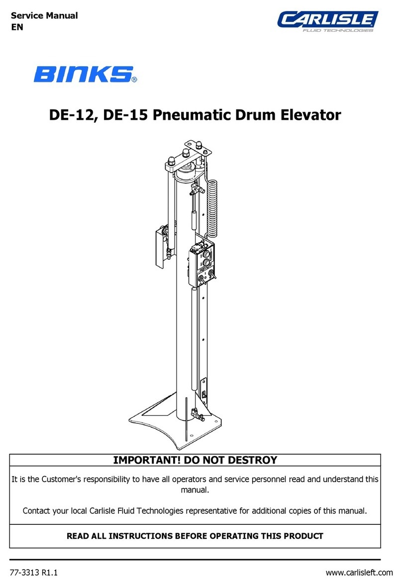
Carlisle Binks DE-12 Service manual

Carlisle

Carlisle Binks DE-12 Service manual

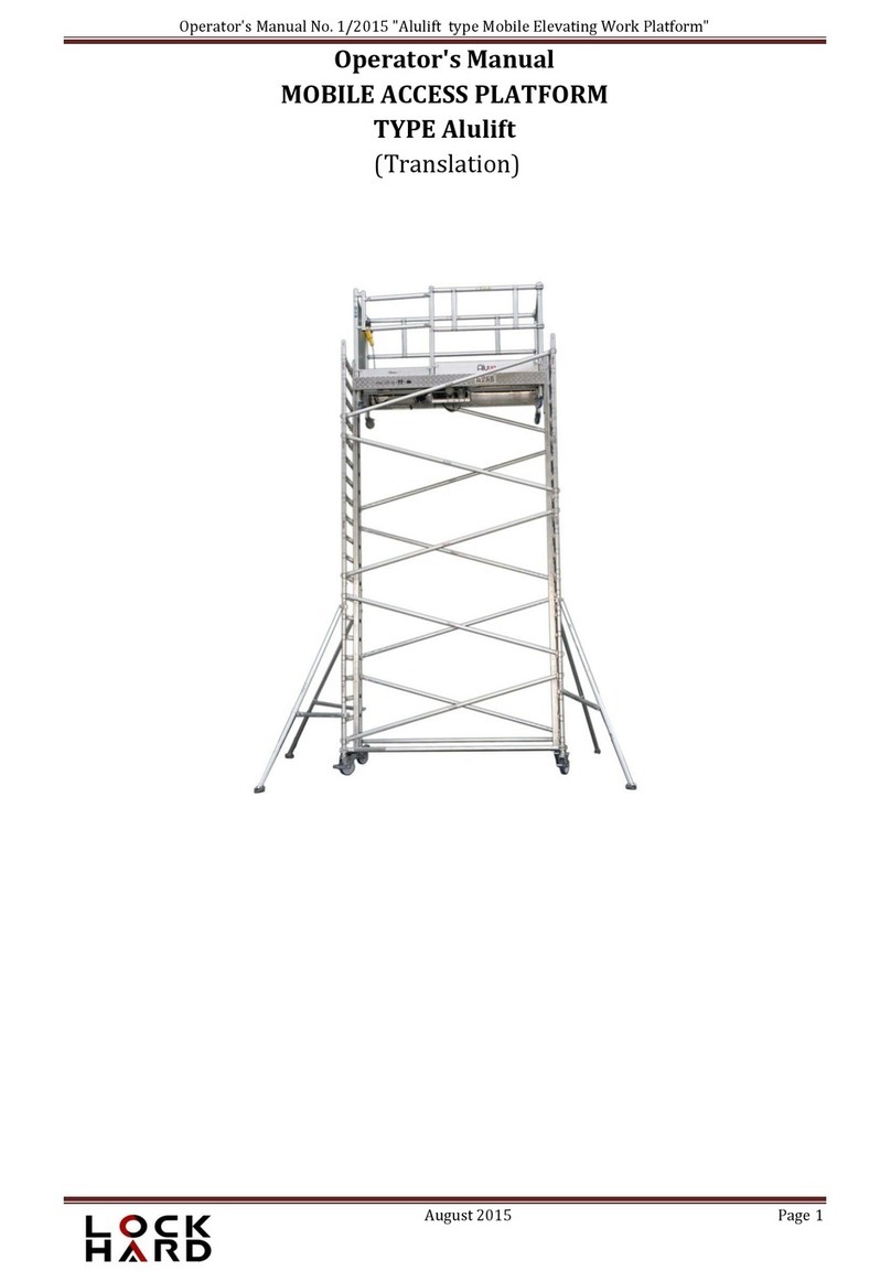
Lockhard Alulift Series Operator's manual

Lockhard

Lockhard Alulift Series Operator's manual

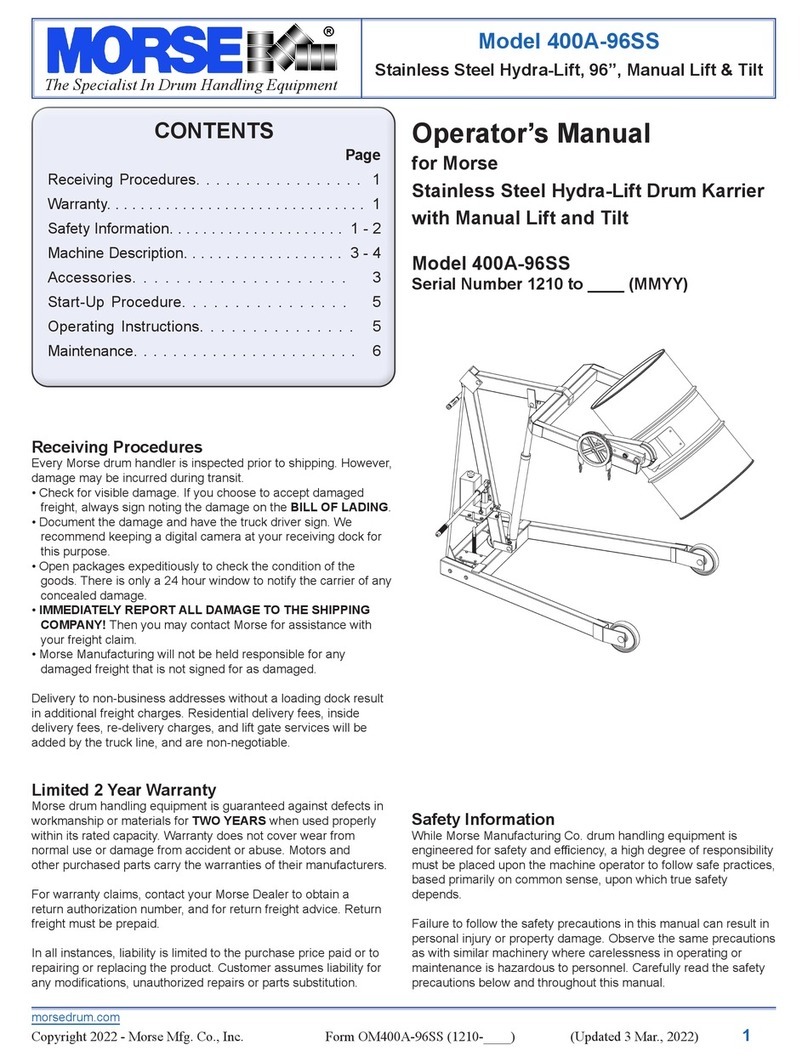
morse 400A-96SS Operator's manual

morse

morse 400A-96SS Operator's manual

Pride Mobility QUANTUM REHAB 088 609 661 manual

Pride Mobility

Pride Mobility QUANTUM REHAB 088 609 661 manual

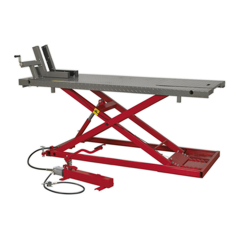
Sealey MC680A manual

Sealey

Sealey MC680A manual

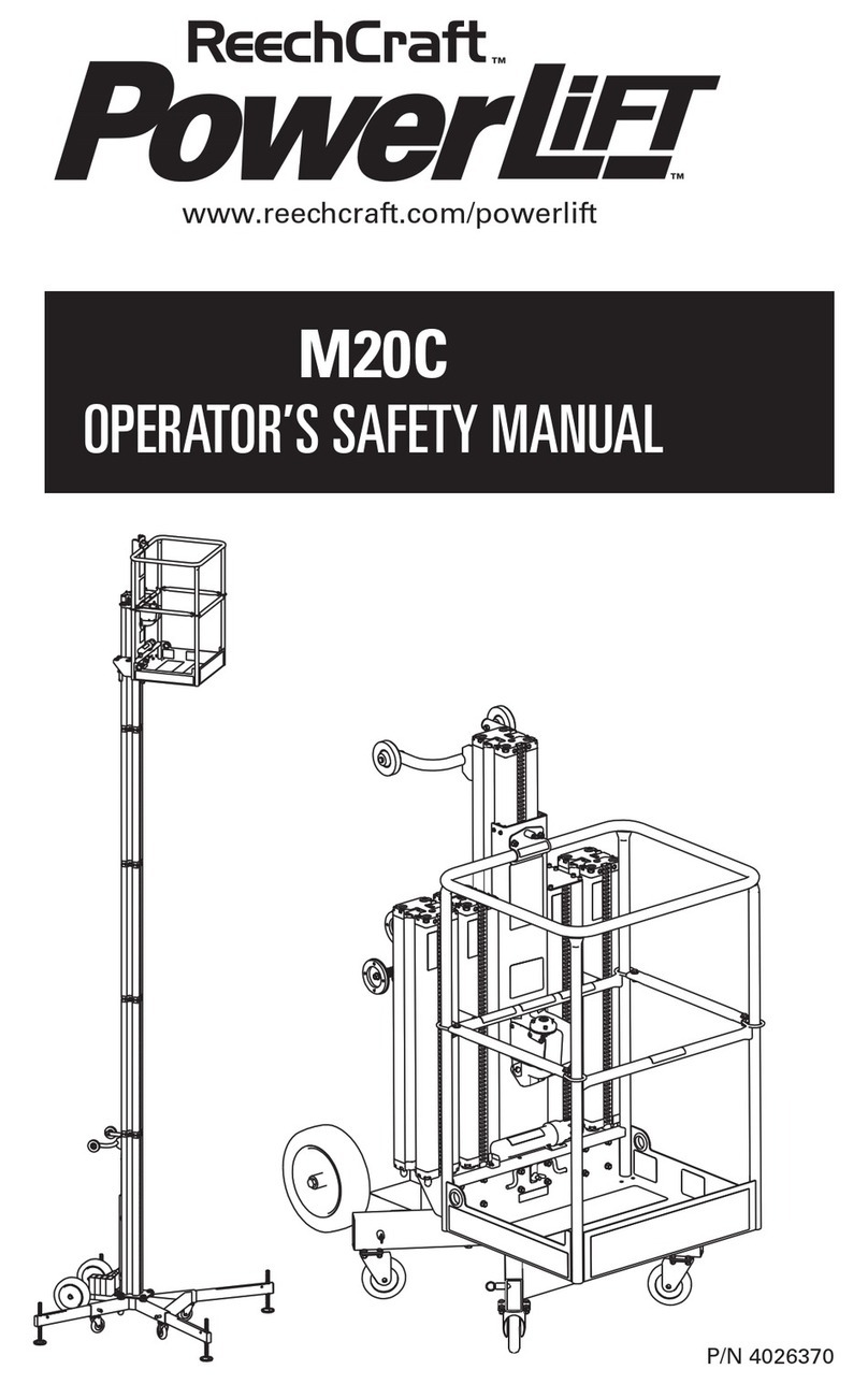
Reechcraft PowerLift M20C Operators safety manual
Reechcraft

Reechcraft PowerLift M20C Operators safety manual

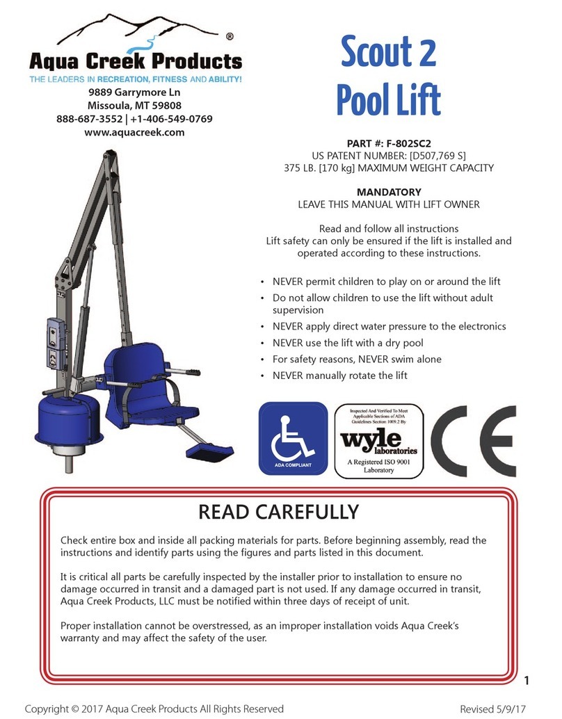
Aqua Creek Products Scout 2 manual

Aqua Creek Products

Aqua Creek Products Scout 2 manual
Perkins 1000 Series User handbook

Perkins

Perkins 1000 Series User handbook
RocwooD RWFSR180 IM instruction manual
RocwooD

RocwooD RWFSR180 IM instruction manual

Jema Autolifte JA5500F Installtion, Operation and Maintenance Instructions
Jema Autolifte

Jema Autolifte JA5500F Installtion, Operation and Maintenance Instructions

Aqua Creek Scout 2 user manual

Aqua Creek

Aqua Creek Scout 2 user manual

manuals.online logo
manuals.online logoBrands
  • About & Mission
  • Contact us
  • Privacy Policy
  • Terms and Conditions

Copyright 2025 Manuals.Online. All Rights Reserved.