Bernina E 16 PRO User manual

E 16 PRO User Manual

2
Table of Contents
1. Copyright Notice............................................................................................................................4
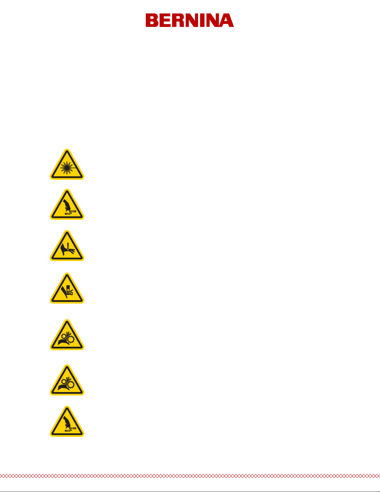
2. Hazards of Operation & Safety Warnings...................................................................................5
3. Specications...............................................................................................................................11
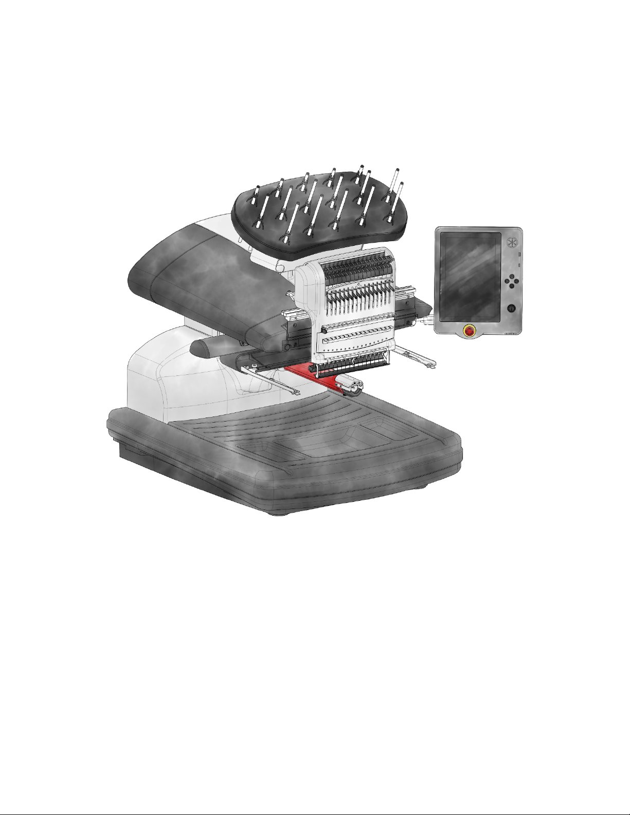
4. Machine Overview & Setup........................................................................................................13
4.1. Cart Assembly....................................................................................................................... 14
4.2. Installing & Adjusting the Screen........................................................................................18
4.3. Powering Up the Machine................................................................................................... 20
5. Threading the Machine...............................................................................................................22
5.1. Upper Threading...................................................................................................................23
5.2. Bobbin Threading & Tensioning......................................................................................... 30
6. Sewing a Design.......................................................................................................................... 37
7. Main Screen................................................................................................................................. 38
7.1. View Window.........................................................................................................................46
8. Loading a Design.........................................................................................................................49
9. Color Sequence........................................................................................................................... 54
9.1. Colorize Thread Tree............................................................................................................60
9.2. Thread Chart Preferences................................................................................................... 62
10. Hoop Selection.......................................................................................................................... 63
11. Machine Speed..........................................................................................................................67
12. Acti-Feed.....................................................................................................................................69
13. Transform.................................................................................................................................. 73
14. Presser Foot Adjustment..........................................................................................................77
15. Trace Design.............................................................................................................................. 79
16. Settings.......................................................................................................................................81
16.1. Network Connection.......................................................................................................... 83
16.2. Design Filter........................................................................................................................ 84
16.2.1. Pull Compensation.......................................................................................................87
16.3. Machine Preferences......................................................................................................... 89

3
16.4. Advanced Acti-Feed Calibration........................................................................................91
16.5. Software Updates...............................................................................................................94
17. Maintenance..............................................................................................................................95
17.1. Head Timing........................................................................................................................ 98
17.2. Sensors.............................................................................................................................. 100
17.3. Needle Case Calibration.................................................................................................. 102
17.4. Steppers............................................................................................................................ 104
18. Hooping....................................................................................................................................107
19. Loading a Hoop onto the Machine....................................................................................... 111
20. Needles.................................................................................................................................... 112
20.1. Replacing A Needle.......................................................................................................... 113
20.2. Needle Types.................................................................................................................... 114
21. Thread Types........................................................................................................................... 116
22. Stabilizers.................................................................................................................................118
23. Attaching & Adjusting Hoop Arms........................................................................................ 122
24. Installing the Wide-Angle Driver............................................................................................124
24.1. Adjusting the Wide-Angle Driver.................................................................................... 129
24.2. Maintaining the Wide-Angle Driver................................................................................ 132
25. Sewing Caps.............................................................................................................................133
25.1. Hooping A Cap.................................................................................................................. 134
25.2. Loading a Hooped Cap.................................................................................................... 141
25.3. Sew Settings For Caps......................................................................................................143

4
1. Copyright Notice
© Copyright Bernina, 2023
ALL RIGHTS RESERVED. No part of this publication may be reproduced, stored in a retrieval system, or
transmitted in any form or by any means (electronic, mechanical, photocopying, recording or otherwise)
without prior written approval from the author. The author reserves the right to revise this publication and to
make changes in it at any time without obligation of the author to notify any person or organization of such
revisions or changes. All precautions have been taken to avoid errors or misrepresentations of facts,
equipment, or products. However, the manufacturer does not assume any liability to any party for loss or
damage caused by errors or omissions. The machine technology is protected by - but not limited to - the
following patents:
·Pat. US 6,445,970 B1
·Pat. US 6,823,807
·Pat. CH 693569 A5
·Pat. US 6,736,077 B2
·Pat. US 6,732,668 B2
·Pat. US 6,871,605
·Pat. US 6,983,192 B2
·Pat. US 7,308,333 B2
·Pat. US 7,513,202
·Pat. US 8,851,001 B2
·Pat. US 9,702,070
·Other patents pending

5
2. Hazards of Operation & Safety Warnings
Hazards of Operation
There are risks in operating any mechanical equipment, the following is intended to elevate your awareness
of both the areas of risk and the meaning of the warning signs located on the machine. Always refrain from
interfering with mechanical or electromechanical parts while in operation unless otherwise specied in this
manual.
Laser Beam
Do not look directly into the laser beam.
Take-up Lever Oscillation
Do not touch the take-up levers during operation.
Needles During Operation
Do not place body parts or other foreign objects under the needles during
operation.
Needle Case Movements
During operation, do not place hands or other objects on or around the needle
case.
Rotary Hook Rotation
Do not attempt to change the bobbin thread during operation. During operation,
do not place hands or other objects in the rotary hook area. Do not operate the
machine without the hook guards in place.
Cap Frame Pinch Points
Do not touch the cap frame, driver, or driver bar during operation.
Pinch Points (X-Carriage)
Do not rest hands or other objects on the tabletop during operation. Do not reach
behind the x-carriage during operation with or without the tabletop in place.

6
Safety Warnings
The list below species safety warnings that you should heed during normal operation and maintenance of
your machine.
Do not attempt to lubricate the machine while it is in operation.
Failure to engage the emergency stop button on the machine keypad while removing
or replacing needles can result in the machine starting through machine or operator
error. This can result in damage to the machine and/or serious personal injury.
Never attempt to remove or insert the bobbin while the machine is operating.
Do not operate the machine without the covers being installed. Moving parts can
cause crushing and pinching injuries. In addition, fabric and other materials can get
caught in the movingbelts and gears and damage the machine.
Do not adjust the presser foot height while the machine is sewing. Doing so can
result in serious injury.
Do not attempt to pull on or trim threads near moving needles. This can result in
painful injury.
The lubricants specied in the Software and Technical manuals contain known
carcinogens. Donot allow lubricants to come into contact with your eyes, mouth, or
nose. Always wash yourhands thoroughly after performing lubrication procedures.
When using solvents to clean components in the machine, always ensure adequate
ventilation. Allow all solvents to completely evaporate before turning the machine
back on to preventshorting out electrical components. Vapors from most solvents
are both toxic and ammable.

7
The following table lists specic safety warnings that you should heed when you perform procedures (such as
repairs and technical adjustments) that extend beyond normal operation and maintenance.
Dispose of rags soaked with solvent properly.
You must unplug the machine before replacing the power switch fuse.
Area of Machine
Warning
Entire Machine
Personal injury may result if proper precautions are not observed.
Remove rings, watches, and any other metallic objects from hands
and wrists before servicing the machine. Remove metallic articles
from shirt pockets to prevent them from falling into the machine.
Do not allow loose clothing to come into contact with moving
parts of the machine. Under certain conditions of machine failure,
the moving parts of the machine may not be controllable by
normal means. At these times, the machine may operate without
notice.
Failure to practice good maintenance and repair techniques may
result in injury to personnel performing the work and/or damage
to the equipment. The warranty is exclusive of, and may be VOID if
poor maintenance practices have caused damage to the
equipment.
Failure to use a grounding strap, or failure to practice other good
maintenance/ repair techniques may cause damage to the
machine and possible personal injury. DO NOT attempt to use any
grounding strap that is not specically designed for static use. A
“straight-wire” grounding device (one without built-in resistance)
will place the operator in danger of exposure to dangerous
voltages. It is recommended that the static strap be checked
during daily use for proper resistance protection.
DO NOT operate the machine with the lower rear cover removed,
except when indicated by the instructions in the Technical Manual.
Operating the machine without the covers creates a risk of severe
electrical-related injury.
Harnesses
Always turn the power o before disconnecting or connecting any
harness. At the minimum engage the emergency stop button.

8
36V Power Harness
Do not attempt to repair a damaged 36V power harness if the
wiring insulation is damaged through chang, nicks, or cuts, or if
the wires were overheated due to an over-current machine error.
Never handle the 36V power harness unless power to the machine
is completely disconnected. Do not rely on the power switch to
break the power supply to the machine.
Power Supply
Lethal voltages exist inside the power supply unit, at the back side
of the electrical supply input connector, and in the wires between
the two. If you plan to do any work with any of these components,
turn the power switch o and disconnect the electrical input
supply cord from the machine.
It is very important that the power cord is plugged into a properly
wired electrical outlet. Failure to have a properly wired outlet may
result in damage to the equipment and personal injury. It is
recommended that a licensed electrician be consulted to ensure
that the electrical outlet is properly wired and grounded. If a
properly wired electrical outlet is not used for the source supply
voltage to the system, electrical failures may result.
Do not attempt to disassemble the power supply unit for any
reason. There are no user-serviceable components inside. Internal
components in the power supply unit might still have residual
voltage (even if power is disconnected) that can cause painful
electrical shock.
Do not attempt to replace or service any component in the rear of
the lower bed without disconnecting the A/C power input cord.
Failure to do so will leave the power supply and power switch
energized with dangerous levels of voltage even when turned o
and can result in severe injury from electrical shock.
Laser Assembly
The laser assembly replacement procedure is intended to be
performed only by specially trained Melco service technicians and
personnel. Disassembly by untrained individuals will void any
warranty protection and can result in personal injury or damage
to the machine.
DO NOT install laser assembly until the machine is turned OFF!!!
Failure to turn the machine o may result in personal injury or
damage to the machine.
The laser light adjustment procedure is intended to be performed
only by specially trained and authorized Melco service technicians
and personnel. Disassembly by untrained individuals will void any
warranty protection and can result in personal injury or damage
to the machine.

9
DO NOT allow the laser beam to be aimed at yours or anyone
else’s eyes. The laser emits a very concentrated light beam that
can cause permanent blindness. Use extreme care in handling the
laser assembly to make sure it is not going to be inadvertently
aimed at someone’s eyes or face. DO NOT LOOK DIRECTLY AT THE
LASER LENS WHILE IT IS ENERGIZED!
LED Cluster Assembly
The LEDs may be hot to the touch when illuminated. They must be
turned o for a few minutes before handling or they can cause
minor burns.
Movable Knife
Keep clear of the moving parts that are exposed during the
movable knife adjustment procedure.
Needle Case
During needle case removal, once you have completed the rst
two steps of the procedure. Do not proceed without engaging the
emergency stop button or by turning the machine o. The
machine may begin operating if you do not do so. This can result
in severe damage to the machine and/or personal injury. You do
not need to disconnect the power input cord from the machine.
Trimmer Drive Assembly
The Trimmer Drive Assembly replacement procedure requires the
removal of the lower arm rear cover from the back of the
machine. DO NOT place your hands into the back of the lower bed
while the A/C input cord is connected to the machine. Failure to
disconnect the A/C power input cord can result in potential
electrical shock if you inadvertently touch the back of the power
switch or the wiring to the power supply.
X/Y Home PCB
A small risk exists of unpredictable movement of internal parts
when the optical sensors are disconnected. This creates a risk of
personal injury if parts suddenly move. Always turn o the
machine before disconnecting the optical sensors.
Y-Motor Assembly
Risk of serious personal injury exists when handling internal
motors, belts, and cabling due to electrical shock and moving
parts hazards. Always turn o the embroidery machine when
working on or adjusting motors, belts, or gears.
Z-Home Sensor PCB
The Z-Home Sensor PCB replacement procedure requires the
removal of the left and right transparent arm covers and the
upper arm back cover. Do not remove the covers from the
machine without either turning the machine o or engaging the
emergency button. The motors might move when the sensor is
removed or the harnesses are disconnected.

10
Safe Operating Principles
The following list contains some safe operating principles you should follow when operating the machine.
·No untrained persons should be permitted within the designated working area around the machine.
·No untrained persons should operate the machine.
·This machine will embroider stitches in a safe and controlled manner when used as outlined
throughout this documentation.
·Thread break sensors stop the machine automatically when a fault changing thread feed dynamics is
detected, this stoppage is normal and recovery from such a stop is explained in this manual.
·The machine will stop operating at the end of each design automatically, do not attempt to manually
stop an operating machine in any way other than what is described in this manual.
·DO NOT interfere with moving machine parts during operation.
·Only after the machine has stopped should you interact with it.
·DO NOT wear loose or baggy clothing or jewelry while operating the machine.
·ALWAYS wear eye protection when operating your machine.
·Keep the working area clean and free from any objects that may interfere with the normal
movements of the machine.
·Keep up on the required maintenance. This not only ensures safe operating conditions but will also
maintain a quality sew-out and extend the life of the machine.
·Read the entire manualprior to operation.

11
3. Specications
For indoor use only.
Number of Needles
16
Maximum Tubular Frame Size (XxY)
500mm x 430mm (19.7″x 16.9″)
Maximum Tubular Frame Size (XxY)
410mm x 393mm (16.1″x15.5″)
Wide Angle Cap Frame
360mm x 82mm (14.1″ x 3.25″)
Min/Max Sew Speed Flats
300-1400 s.p.m.
Min/Max Sew Speed (Wide Angle Driver)
300-1200 s.p.m.
Stitch Length Range
Only limited by hoop sew eld.
User Interface
Connected Onscreen Touch Environment
Machine Conguration
One machine is connected to one
touchscreen unit.
Self-Diagnostics Capability
Retrieves relevant machine data for
troubleshooting
Touchscreen Design Memory
≈6GB, Max le size 500k
Supported Design Files
.OFM (≥v9), .ARTX, .EXP, .DST
Pre-Sew Trace
Laser
Needle to Garment, Garment to Hoop Position
Laser Positioning System
Thread Feed Technology
Patented Acti-Feed
Thread Break Detection
Upper & Lower Electronic Force Gauge
Sensor
Automatic Stitch Backup
Yes
Automatic Trimmer
Yes
Lighting Type Cold Bright
Cold bright LED

12
Power Supply (V)
90-260V (Single Phase, 50/60 HZ, 4A),
Class I (Grounded)
Power Consumption (W)
120V AC / 240V AC (480 Watts)
Temperature Range
15-40° C
Humidity
Max 85% Relative Humidity
Installation Category (overvoltage)
II
Pollution Degree
2
Motor Type(s)
Servo, Stepping
Motor Capacity (kV)
X and Z: 100 Watts Y: 250 Watts
Machine Construction Material
Aluminum
Physical Specications with Cart
Width
847mm (33.4″)
Height
1684mm (thread tubes 130mm extended)
(66.3″)
Depth
848mm (33.4″)
Weight
100.2kg (221 lbs)
Physical Specications without Cart
Width
847mm (33.4″)
Height
950mm (thread tubes 130mm extended)
(37.4″)
Depth
848mm (33.4″)
Weight
75.7kg (167 lbs)

13
4. Machine Overview & Setup
1. Thread Tree
2. Thread Feed Rollers
3. Touchscreen Control Panel
4. Needle Case
5. Left Side Cover
6. Right Side Cover
7. Hoop Arms
8. Lower Arm
9. Ethernet Inlet (On Back)
10. Power Inlet (On Back)

14
4.1. Cart Assembly
The cart consists of the items assembled as shown.
Tool Required
·4mm hex wrench (like the one included in the machine operator's kit)
Prior to assembly of the art, place cardboard or a blanket on the oor to prevent damaging cart parts.
Assembly
Assembly of the cart is easiest on the oor. If you are concerned with marking up the cart or
oor, begin by placing down a large piece of cardboard or a blanket.
The assembly of the larger pieces may be easier with two people. One person can hold while the other
attaches. It isn't necessary, but it can make assembly smoother.
Item
Quantity
Description
Image
A
1
Left Cart Leg Assembly
B
1
Right Cart Leg Assembly
C
1
Cart Base Support
D
1
Cart Rear Support
E
14
M6 x 1.0 x 12mm Button
Head Screw
F
18
M6 Flat Washer
G
1
Cart Shelf
H
4
Locator
I
4
M6 Split Lock Washer
J
4
M6 x 1.0 x 16mm Button
Head Screw

15
Stage 1 - Attaching the Base Support
1. Place items A and B (Cart Leg
Assemblies) on the oor with the
Casters facing up. The Casters with
the brake face the front of the Cart.
2. Assemble Item C (Base Support) into
the cutouts (see red highlights)
located on each side of both Cart
Legs, Items A and B, as shown.
3. Install (6 each) items E and F (M6 x
12mm Screw and M6 Washer) at the
locations shown. Assemble loosely,
do not tighten.
4. Fully tighten all (6) item E Screws.
Stage 2 - Installing the Rear Support
1. Rotate the Cart to its upright
position.
2. Assemble Item D (Rear Support) to
the rear side of the Cart resting on
Item C (Base Support), with the
obround opening facing towards the
bottom of the Cart.
3. Install (4 each) items E and F (M6 x
12mm Screw and M6 Washer) at the
locations shown. Assemble loosely,
do not tighten.
4. Fully tighten all (4) item E Screws.

16
Stage 3 - Installing the Machine Locators
1. Install items J, I, and F (M6 x 16mm
Screw, M6 Lock Washer, and M6
Washer) from the bottom side of
item G (Cart Shelf) as shown.
2. Install item H (Machine Locator) onto
item J (Screw) from the top side of
item G (Cart Shelf) as shown.
3. Fully tighten items H (Machine
Locator) and J (Screw).
4. Repeat steps 1-3 for the (3)
remaining sets of items J, I, F, and H
at the (3) remaining corners of item G
(Cart Shelf).
Stage 4 - Installing the Cart Shelf
1. Position item G (Cart Shelf) between
the two Cart Legs, items A and B,
with the (4) Machine Locators (item
H) resting on the Cart Legs, items A
and B.
IMPORTANT: The side of item G
(Cart Shelf) labeled with the “F”
sticker (with the two Machine
Locators (item H) positioned closer to
the edge) faces the front of the Cart.
2. Install (2 each) items E and F (M6 x
12mm Screw and M6 Washer) at locations shown towards the front of the Cart.

17
Note: Lift up item G (Cart Shelf) slightly to align item E (Screw) with the threaded inserts in the Cart
Legs (items A and B). Assemble loosely, do not tighten.
3. Install (2 each) items E and F (M6 x 12mm Screw and M6 Washer) at locations shown towards the back
side of the Cart.
Note: Lift up item G (Cart Shelf) slightly to align item E (Screw) with the threaded inserts in the Cart
Legs (items A and B). Assemble loosely, do not tighten.
4. Fully tighten all (4) item E Screws.
Cart Assembly Complete!
With two people, lift the machine onto the Cart so the (4) Machine Locators (item H) on top of the Cart are
centered over the round bosses on the bottom side of the Machine.
Warning!!
Do not attempt to lift the machine by yourself. Always move the machine with two people. Do not lift
the machine at any points other than the Lift Handles indicated by the “LIFT HERE” stickers in the
machine packaging. Otherwise, damage to sensitive parts might result.

18
4.2. Installing & Adjusting the Screen
Installing the Touchscreen
1. Locate the box containing the Touchscreen Assembly and X-Beam End Caps. The box is labeled with
the following:
2. Attach the Touchscreen Assembly.
a. Using the two screws and two lock Washers that came with the Touchscreen Assembly, attach
the Touchscreen Assembly as shown in the image using a 5mm hex wrench (provided in the
Machine Operator’s Kit).
b. Route the cable (shown in red) from under the right-side Machine Cover and plug it into the
back of the Touchscreen Assembly.
Note:

19
Adjusting the Touchscreen Angle
1. Locate the tightening knob on the back of the touchscreen assembly.
2. Loosen the knob by turning it counterclockwise.
3. Tilt the touchscreen to the desired angle.
4. Tighten the knob by turning it clockwise. This will hold the touchscreen angle where set.
If present, the protective film can be removed from the screen after installation.
Caution!
Do not adjust the touchscreen without rst loosening the adjustment knob.

20
4.3. Powering Up the Machine
Connecting the Power Cable
1. Locate the power cable you will be using with your machine.
2. Locate the power cable plug in the rear of the machine.
3. Make sure the machine power switch is in the OFF position. Plug the power cable into the inlet.
4. Connect the power cable to a power source.
Initial Power Up
1. Make sure the E-Stop is disengaged by turning it in the direction of the arrows.
2. Power up the machine with the power switch located on the rear of the machine (just above the
power inlet).
Information
It is recommended that a line conditioner or an uninterruptible power supply with a line conditioner
be used with your machine. If using this, connect the power cord to the conditioner, and the
conditioner to the power source.
Table of contents