DEMA 633GAP Series User manual
DEMA BLEND CENTER
MODELS: 633GAP
INSTALLATION INSTRUCTIONS
I-784 Pg. 1 of 6
Rev. J-42084 9/8/16
The 633GAP Series Blend Center modular design lets you easily couple together any number of stations to create a system that meets
your specific needs. Mix and match both high and low flow units for filling spray bottles, buckets, sinks and other reservoirs. Choose
from blue, red, green, yellow, black and white buttons.
1. PARTS:
ITEM
DESCRIPTION
QTY.
A.
Blend Center Assembly
1
B.
¼” ID or 3/8" I.D. X 8’ Long Vinyl Supply Tubing & Foot Valve Assembly
1
C.
Ceramic Weight For 1/2” OD or 3/8" OD Vinyl Supply Tubing
1
D.
½” ID X 6” Long Vinyl Outlet Tubing (For 1 GPM Station Only) or
½” ID X 6’ Long Vinyl Outlet Tubing (For 4 GPM Station Only)
1
E.
#10 Screws & Anchor Kit Set (2 #10 Screws & 2 #10 Anchors
1
F.
Chemical Label
2
G.
Metering Tip Kit
1
2. INSTALLATION:
Note: All installations must conform to local plumbing codes and use the approved backflow preventers. Pressure
indicating tee is to be installed with existing faucets according to local plumbing codes in the state of Wisconsin and any
other state that requires the use of a pressure indicating tee.
WARNING: Water supply should not exceed 125 psi and water temperature must not exceed 150°F.
A. Mounting & Water Supply: Remove the two cover retainer screws and the cover from the Blend Center assembly. Any
number of Blend Centers can be coupled together by first removing the pipe plugs in all but the last unit, then connecting
the male hose thread of one unit to the female inlet hose adapter of the next unit. Mount the unit(s) in position on the wall
and locate the position for the mounting screws. Only two screws are necessary to mount up to four units coupled together.
Drill all of the holes into the drywall using a ¼” diameter bit for use with the included #10 screw and anchor set. (If
mounting the Blend Center to wood and you do not plan to use the included anchors, drill 1/8” diameter holes.) Insert the
anchors into drilled holes and hammer them into the wall until they are flush with face of wall. Mount the units(s) to the
wall and replace the covers and screws.
The water inlet is equipped with a female garden hose fitting (with strainer washer) for attaching a water supply hose. The
unit is designed so water can be supplied to either side by interchanging the pipe plug and the female hose fitting. Note:
Apply pipe dope, hand-tighten, and then turn 1-1/2 times with a wrench. DO NOT OVER TIGHTEN.
WARNING: Do not use Teflon® tape to seal internal plastic threads as the extra thickness of the tape may
cause the plastic to crack. Use a non-welding liquid sealant instead.
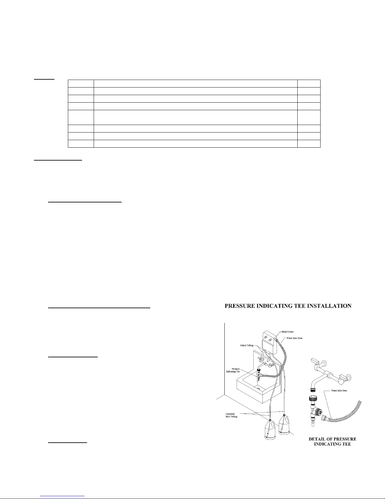
B. Pressure Indicating Tee Installation: Screw female quick
disconnect to faucet and attach pressure indicating tee to female
quick disconnect. Attach female end of reinforced hose to male
threads of tee, then attach the male end to the female garden
hose fitting at the water inlet of the Blend Center (See Figure to
the right).
C. Chemical Supply: Place the chemical containers in a
convenient location not more than 6 feet below the Blend
Center (greater lifts will reduce injection capacities). Slip
ceramic weight over the chemical supply tubing and insert the
foot valve end of the tubing into the chemical container. Cut
the vinyl tubing to any convenient length that will allow the
chemical supply tubing to extend from the bottom of the
chemical container to the proportioner inlet barb. (See Figure
1) Install the tubing by pushing tubing over the barb located on
the proportioner. Gummed labels are provided for labeling
chemicals.
D. Outlet Tubing: Cut the 1/2" I.D. outlet tubing to the desired
length and attach it to the proportioner outlet barb. NOTE: DO
NOT force outlet tubing onto the larger barbs on the proportioner.

DEMA BLEND CENTER
MODELS: 633GAP
INSTALLATION INSTRUCTIONS
I-784 Pg. 2 of 6
Rev. J-42084 9/8/16
E. Chemical Injection Adjustment: WARNING: USE CARE WHEN HANDLING HAZARDOUS CHEMICALS.
Chemical feed rates are controlled by metering tips screwed into the proportioner barbs. Select a tip for each barb
using Table 1 or 2 for ¼” barb and Table 3 or 4 for 3/8” barb as a guide.
1 cps (centipoise) is equal to the viscosity of water
75 cps is approximately equal to the viscosity of 10 weight motor oil
200 cps is approximately equal to the viscosity of most dishwashing detergents
TABLE 1
1 GPM FLOW RATE PROPORTIONER, ¼” I.D. TUBING
Metering Tip Color
Injection Rates For Viscosities Shown
1 cps
75 cps
200 cps
Oz/Gal
Ratio
Oz/Gal
Ratio
Oz/Gal
Ratio
Tan
1.03
125-1
0.76
168-1
0.38
333-1
Orange
1.24
103-1
0.98
130-1
0.53
241-1
Turquoise
1.43
89-1
1.07
119-1
0.61
211-1
Pink
2.47
52-1
1.58
81-1
0.92
139-1
Light Blue*
3.05
42-1
2.1
61-1
1.06
121-1
Brown
3.48
37-1
2.31
55-1
1.15
111-1
Red
4.38
29-1
2.83
45-1
1.23
104-1
White
5.33
24-1
3.1
42-1
1.37
93-1
Green
6.38
20-1
3.63
35-1
1.4
91-1
Blue
6.77
19-1
3.78
34-1
1.45
88-1
Yellow
9.90
13-1
5.1
25-1
1.48
86-1
Black
15.00
9-1
6.54
20-1
1.53
84-1
Purple
24.94
5-1
7.28
18-1
1.57
82-1
Gray
35.94
4-1
8.5
15-1
1.64
78-1
No Tip
73.21
2-1
9.35
14-1
1.87
69-1
TABLE 2
4 GPM FLOW RATE PROPORTIONER, ¼” I.D. TUBING
Metering Tip Color
Injection Rates For Viscosities Shown
1 cps
75 cps
200 cps
Oz/Gal
Ratio
Oz/Gal
Ratio
Oz/Gal
Ratio
Tan
0.33
387-1
0.26
500-1
0.12
1090-1
Orange
0.42
307-1
0.32
430-1
0.17
735-1
Turquoise
0.51
251-1
0.34
382-1
0.19
676-1
Pink
0.78
165-1
0.56
230-1
0.3
422-1
Light Blue*
0.87
147-1
0.67
192-1
0.33
391-1
Brown
0.99
129-1
0.74
174-1
0.37
345-1
Red
1.37
93-1
0.91
141-1
0.44
289-1
White
1.52
84-1
1.04
123-1
0.48
264-1
Green
1.72
74-1
1.22
105-1
0.52
244-1
Blue
2.13
60-1
1.27
101-1
0.54
239-1
Yellow
3.05
42-1
1.71
75-1
0.56
229-1
Black
4.50
28-1
1.96
65-1
0.57
224-1
Purple
7.75
17-1
2.4
53-1
0.59
217-1
Gray
9.86
13-1
2.54
50-1
0.63
204-1
No Tip
19.63
7-1
3.16
40-1
0.67
190-1
NOTE:
*Metering tip color was formerly clear.
All induction rates are based on a water pressure of 40 psi.
Leaner dilutions can be achieved by ordering DEMA ultra lean tip kit 100-15KU for ¼” chemical supply inlet barb only.

DEMA BLEND CENTER
MODELS: 633GAP
INSTALLATION INSTRUCTIONS
I-784 Pg. 3 of 6
Rev. J-42084 9/8/16
TABLE 3
1 GPM FLOW RATE PROPORTIONER, 3/8” I.D. TUBING
Metering Tip Color
Injection Rates For Viscosities Shown
1 cps
75 cps
200 cps
Oz/Gal
Ratio
Oz/Gal
Ratio
Oz/Gal
Ratio
Clear
2.28
56-1
0.63
204-1
0.44
292-1
Purple
2.98
43-1
1.22
105-1
0.76
168-1
Yellow
5.18
25-1
2.51
51-1
2.01
64-1
Green
6.37
20-1
4.22
30-1
3.14
41-1
Pink
8.76
15-1
5.59
23-1
4.17
31-1
Turquoise
12.01
11-1
8.44
15-1
6.12
21-1
Black
15.16
8-1
9.93
13-1
7.09
18-1
Gray
18.97
7-1
12.55
10-1
8.73
15-1
Red
25.38
6-1
15.84
8-1
10.07
13-1
Blue
28.24
5-1
17.92
7-1
11.7
11-1
Brown
36.99
4-1
21.31
6-1
12.04
10.5-1
White
45.52
3-1
25.26
5-1
12.67
10-1
Orange
53.31
2.5-1
28.44
4.5-1
13.14
9.75-1
Light Blue**
60.27
2.25-1
30.5
4-1
13.51
9.5-1
Tan**
72.94
2-1
33.4
3.75-1
14
9-1
No Tip
77.90
1.75-1
35.85
3.5-1
14.5
8.75-1
TABLE 4
4 GPM FLOW RATE PROPORTIONER, 3/8” I.D. TUBING
Metering Tip Color
Injection Rates For Viscosities Shown
1 cps
75 cps
200 cps
Oz/Gal
Ratio
Oz/Gal
Ratio
Oz/Gal
Ratio
Clear
0.30
430-1
0.22
592-1
0.13
864-1
Purple
0.48
265-1
0.32
406-1
0.24
524-1
Yellow
1.28
100-1
0.82
157-1
0.6
212-1
Green
1.67
77-1
1.29
99-1
1
128-1
Pink
2.36
54-1
1.65
77-1
1.25
103-1
Turquoise
3.76
34-1
2.55
50-1
1.85
69-1
Black
4.47
29-1
3.03
42-1
2.12
60-1
Gray
5.53
23-1
3.67
35-1
2.58
50-1
Red
7.00
18-1
4.79
27-1
2.79
46-1
Blue
8.78
15-1
5.39
24-1
3.06
42-1
Brown
10.95
12-1
6.49
20-1
3.35
38-1
White
14.19
9-1
7.08
18-1
3.46
37-1
Orange
17.58
7-1
7.91
16-1
3.71
35-1
Light Blue**
21.75
6-1
8.66
15-1
3.9
33-1
Tan**
27.98
5-1
9.15
14-1
4.11
31-1
No Tip
33.15
4-1
10.54
12-1
4.52
28-1
** These tips are not included in the standard tip pack.
3. OPERATION:
The Blend Center is now ready for use. Depressing a push button opens the valve, allowing water to flow through the chemical
proportioner that mixes chemical at the desired rate. The buttons are spring loaded to prevent accidental overflow if unattended,
but may be converted to locking buttons by cutting off the tab, at the notch (See Figure 2). Pushing the button and turning it a
1/4 turn clockwise at the end of its travel allows the valve to lock on. This makes it unnecessary for the attendant to hold the
button in while filling large containers. Turning the button in a counterclockwise direction will release it, allowing the valve to
shut off.
4. SERVICING:
CAUTION: TURN OFF WATER SUPPLY BEFORE SERVICING.
A. Proportioner fails to draw chemical:
1. Pinch outlet tube to create back pressure, which will cause unit to prime. The foot valve will then keep the inlet tube
primed.
2. Insufficient water supply pressure. 20 PSI is the minimum allowable.
B. Proportioner stops drawing chemical:
1. Inspect foot valve for dried chemical or dirt. Soak in hot water to clean.
2. Proportioner metering tip clogged with dried chemical. Remove tip and try injecting in hot water. If there is no

DEMA BLEND CENTER
MODELS: 633GAP
INSTALLATION INSTRUCTIONS
I-784 Pg. 4 of 6
Rev. J-42084 9/8/16
suction, remove proportioner and soak in hot water to clear interior passages.
3. Inspect proportioner to ensure that there are no mineral deposit build-ups on the nozzle. If so, soak proportioner body
in de-liming solution. (Remove all parts attached to proportioner before soaking in de-liming solution.) Note: Use care
when handling hazardous chemicals.
C. Proportioner continues to draw chemical after water valve closes:
Chemical supply is higher than bottom of discharge tube creating a natural siphon. Lower the supply vessel or hang up
outlet tube after use.
D. Valve Malfunction:
Check that the button moves freely up & down and
that a "click" can be heard when the button is pushed
and released, indicating that the magnet is activating
the plunger properly. Remove cover to inspect
internal parts, unscrew magnet housing and carefully
pull off the enclosing tube so as not to drop the
plunger, kick-off spring and spacer. Check for dirt or
damage impeding plunger and kick-off spring
movement. Inspect the diaphragm, making sure the
two small pinholes (bleed holes) in the diaphragm
convolution are clear to allow the valve to close.
CAUTION: When servicing unit, be sure that
replacement parts have been
installed according to the drawing.
RETURNS: NO MERCHANDISE MAY BE RETURNED FOR CREDIT WITHOUT DEMA’S WRITTEN
PERMISSION. RETURN MERCHANDISE AUTHORIZATION NUMBER REQUIRED IN ADVANCE OF
RETURN.
WARRANTY: DEMA products are warranted against defective material and workmanship under normal use and service for one
year from the date of manufacture. This limited warranty does not apply to any products, which have a normal life
shorter than one year or failure and damage caused by chemicals, corrosion, improper voltage supply, physical
abuse, or misapplication. Rubber and synthetic rubber parts such as “O”- rings, diaphragms, squeeze tubing and
gaskets are considered expendable and are not covered under warranty. This warranty is extended only to the
original buyer of DEMA products. If products are altered or repaired without prior approval of DEMA, this
warranty will be void.
Defective units or parts should be returned to the factory with transportation prepaid. If inspection shows them to be
defective, they will be repaired or replaced without charge, F.O.B. factory. DEMA assumes no liability for
damages. Return merchandise authorization number, to return units for repair or replacement, must be granted in
advance of return.
Utility Knife
FIGURE 2
Vinyl Discharge Tubing
Push Button
FIGURE 1
Foot Valve
Ceramic
Weight
Chemical Container
Metering Tip
Mounting Holes
Inlet Hose Adapter
Proportioner
Action Gap
Pipe Plug
Push Button Actuator
and O-Ring
Chemical Supply Tubing
Strainer Washer

DEMA BLEND CENTER
MODELS: 633GAP
INSTALLATION INSTRUCTIONS
I-784 Pg. 5 of 6
Rev. J-42084 9/8/16
NO.
PART NO.
DESCRIPTION
1
66-139
Magnet Housing (Specify Color)
2
66-140
Push Button (Specify Color)
3
63-35
Magnet
4
63-36
Spring
5
41-7-25
Enclosing Tube
6
63-87
Valve Repair Kit
7
63-37
Spacer
8
41-1-8
Kick-off Spring
9
63-38
Plunger
10
41-15-10
Diaphragm
11
63-39
Valve Body
12
100-38
Strainer Washer
13
93-44
Swivel Adapter w/Strainer Washer
14
66-153
Pipe Plug & O-Ring Assy.
15
16-30
Action Gap Assembly
16
61-22-3
4 GPM (1/4” Barb) Prop. (Gray)
17
61-99-2
1 GPM (1/4” Barb) Prop. (Green)
18
61-22-2
4 GPM (3/8” Barb) Prop. (Gray)
19
61-99-1
1 GPM (3/8” Barb) Prop. (Green)
20
63-78
O-Ring
NO.
PART NO.
DESCRIPTION
21
63-79
Inlet Barb (1/4” Barb)
22
63-80
Inlet Barb (3/8” Barb)
23
100-15K
Metering Tip Kit (14 Sizes) (1/4”
Barb)
24
61-9K
Metering Tip Kit (15 Sizes) (3/8”
Barb)
25
16-3-6
½” ID X 6” Lg. Vinyl Outlet Tube
(1 GPM Only)
26
61-21
½” ID X 6’ Lg. Vinyl Outlet Tube
(4 GPM Only)
27
100-12
¼” ID X 8’ Lg. Vinyl Supply
Tubing
28
100-12L
3/8” ID X 8’ Lg. Vinyl Supply
Tubing
29
61-107-2
Ceramic Weight (3/8” OD Tube)
30
61-107
Ceramic Weight (1/2” OD Tube)
31*
100-16E
Foot Valve
32
63-45
Cover
33
63-46
Screws (2 Required)
341
L307
Chemical labels
351
L366
Unit front label
ACCESSORIES
NO.
PART NO.
DESCRIPTION
34
68-6-QD2
Pressure Indicating Tee
*Foot Valve also available with silicone (100-16S) or Viton (100-16V) rubber seals. Please specify material when ordering.
1. Items 34 and 35 are not shown.
2
13
14
26 (6' Long Tubing)
25
20
23
(6" Long Tubing)
21 24
(1/4" BARB) (3/8" BARB)
breakdown
See page 8 for
FOR THE
1/4" BARB
breakdown
See page 8 for
15
16 18
17 19
FOR THE
3/8" BARB 22
9
FOR 3/8" TUBE
30
31
FOR 1/4" TUBE
11
FOR 1/4" TUBE
FOR 3/8" TUBE
29
28
27 10
6
7
8
5
33
3
4
SPECIFY
COLOR
34
12 32 1
SPECIFY
COLOR

DEMA BLEND CENTER
MODELS: 633GAP INSTALLATION INSTRUCTIONS
I-784 Pg. 6 of 6
Rev. J-42084 9/8/16
NO.
PART NO.
DESCRIPTION
1
150-6
Rubber Washer
2
61-36
Flow Disk
3
16-3-6
1/2” I.D. x 6” Lg. Vinyl Outlet Tube (1 GPM Only)
4
61-21
1/2” I.D. x 6’ Lg. Vinyl Outlet Tube (4 GPM Only)
5
63-89-1
Rubber Washer (1/32” Thick)
6
16-30
Action Gap Assembly
3
1
2
4
1
5
6
Table of contents
Other DEMA Laboratory Equipment manuals

DEMA
DEMA 163CH User manual

DEMA
DEMA 700 Series User manual

DEMA
DEMA 203BS-2EP User manual

DEMA
DEMA 292QD AERATING WAND User manual

DEMA
DEMA Fusion One Assembly instructions

DEMA
DEMA 633AG-1 User manual

DEMA
DEMA 162HCGHT User manual

DEMA
DEMA 681GAP-2P User manual

DEMA
DEMA 94235 User manual

DEMA
DEMA 633MB User manual

Popular Laboratory Equipment manuals by other brands


MOGlabs
MOGlabs FZW600 manual

Thermo Scientific
Thermo Scientific Heraeus Multifuge X3 F Instructions for use

Koehler
Koehler K1223 Series Operation and instruction manual

Endress+Hauser
Endress+Hauser Cleanfit CPA875 operating instructions

SPEX SamplePrep
SPEX SamplePrep 6875 Freezer/Mill Series operating manual

Behncke
Behncke UV matic A20 user manual