Berthold castxpert LB 452 User manual

Evaluation unit
LB 452
Operating Manual
47344BA2
Rev. No.: 05, 05/2019
Embedded Software as of vers. 1.5.1 (CU) and 1.5.1 (MU)

BERTHOLD TECHNOLOGIES GmbH & Co. KG
Calmbacher Str. 22
75323 Bad Wildbad, Germany
www.berthold.com
Telephone +49 7081 177-0
Fax +49 7081 177-100
industr[email protected]

LB 452
1 About this Manual
47344BA2 Rev.05, 05/2019
3
Table of Contents
1About this Manual.............................................................................................. 5
1.1 Some Prior Remarks...................................................................................................... 5
1.2 Storage Place ................................................................................................................ 5
1.3 Target Group ................................................................................................................ 5
1.4 Validity of the Operating Manual............................................................................... 6
1.5Structure of the Manual .............................................................................................. 6
1.6 Copyright ...................................................................................................................... 6
1.7 Target Group ................................................................................................................ 6
1.8 Representation ............................................................................................................. 6
1.9 Warning notes .............................................................................................................. 7
1.9.1 Symbols Used in the Operating Manual ..................................................................... 7
1.9.2 Symbols Used on the Device ........................................................................................ 8
1.10 Conformity .................................................................................................................... 9
2Safety ................................................................................................................ 10
2.1 Dangers and safety measures .................................................................................... 10
2.2 Proper use ................................................................................................................... 10
2.4 Qualification of the Personnel .................................................................................. 11
3Product Description .......................................................................................... 13
3.1 Description of the System .......................................................................................... 13
3.2 Software...................................................................................................................... 13
3.3 Power Supply .............................................................................................................. 13
3.4 Overview ..................................................................................................................... 14
3.4.1 Back View.................................................................................................................... 15
3.5 Radiometric Measurement System............................................................................ 17
3.5.1 Functional Principle.................................................................................................... 17
3.5.2 Measurement System Components/Measurement Setup........................................ 18
4Start-Up............................................................................................................. 20
4.1 Installation of the Evaluation Unit (EVU) ................................................................. 20
4.2 The Use of a Terminal Box ......................................................................................... 23
4.3 Configuring the Current Output............................................................................... 24
4.3.1 Configuring the Current Output on the Basic Module............................................ 25
4.3.2 Configuring the Current Output on Extension Module .......................................... 28
4.4 Data Definition Profibus DP ...................................................................................... 29
4.5 Installation/Removal of an SD Card........................................................................... 31
5Operation of the Software............................................................................... 32
5.1 Overview of the Standard Display............................................................................. 33
5.2 Operation of the EVU ................................................................................................ 35
6The System Menu ............................................................................................. 37
6.1 Channel Setting .......................................................................................................... 39
6.1.1 Channel Names ........................................................................................................... 40
6.2 Calibration Rig ............................................................................................................ 41
6.3 Settings........................................................................................................................ 42
6.3.1 Setting the Date/Time ................................................................................................ 43
6.3.2 Applying Network Settings........................................................................................ 46
6.3.3 Display ......................................................................................................................... 48
6.3.4 Setting Language ....................................................................................................... 50
6.3.5 Setting Dimensions and Temperature Unit .............................................................. 51
6.4 Data Log...................................................................................................................... 52
6.4.1 Graph........................................................................................................................... 52

1 About this Manual
LB 452
4
47344BA2 Rev.05, 05/2019
6.4.2 Data Logger ................................................................................................................ 53
6.4.3 Network Logger.......................................................................................................... 55
6.5 Service Submenu......................................................................................................... 59
6.5.1 Remote Control Software .......................................................................................... 60
6.5.2 Export Complete Service Data ................................................................................... 61
6.5.3 Software update......................................................................................................... 62
6.6 Access Level................................................................................................................. 68
7Menu Channel Overview .................................................................................. 70
7.1 Empty and Full Adjustment ....................................................................................... 74
7.2 Settings........................................................................................................................ 77
7.2.1 Calibration .................................................................................................................. 79
7.2.2 Filter ............................................................................................................................ 88
7.2.3 Alarms ......................................................................................................................... 90
7.2.4 Option/Display ............................................................................................................ 91
7.3 In/Outputs ................................................................................................................... 92
7.3.1 Analog IO .................................................................................................................... 93
7.3.2 Digital IO ..................................................................................................................... 99
7.4 Error........................................................................................................................... 104
7.4.1 Overview ................................................................................................................... 105
7.5 Service ....................................................................................................................... 106
7.5.1 Exporting Service Data............................................................................................. 107
7.5.2 Change Log ............................................................................................................... 108
7.5.3 Backup....................................................................................................................... 109
8Troubleshooting ............................................................................................. 111
8.1 Error Search............................................................................................................... 111
8.2 Error Codes of the Evaluation Unit ......................................................................... 112
8.2.1 System ....................................................................................................................... 112
8.2.2 Main board ............................................................................................................... 113
8.2.3 Application................................................................................................................ 114
8.2.4 GAMMAcast Control ................................................................................................ 115
8.2.5 Process Connection................................................................................................... 116
9Maintenance ................................................................................................... 117
9.1 Installation of Modules ............................................................................................ 117
9.1.1 Installation of the Basic Module/Extension Module .............................................. 119
9.1.2 Installation of the Fieldbus Module........................................................................ 120
9.2 Replacing of Fuses .................................................................................................... 122
9.2.1 Replacing of Basic Module Fuse .............................................................................. 123
9.2.2 Replacing of Extension Module Fuse ...................................................................... 124
9.3 Cleaning .................................................................................................................... 125
10 Decommissioning............................................................................................ 126
10.1 Disposal of Measurement System............................................................................ 126

LB 452
1 About this Manual
47344BA2 Rev.05, 05/2019
5
1About this Manual
1.1 Some Prior Remarks
The product is handed over to you by the manufacturer BERTHOLD TECHNOLOGIES
GmbH & Co. KG (designated as Berthold in the following) in a complete and func-
tionally reliable condition.
This manual demonstrates to you how to:
•Assemble/Install the EVU (evaluation unit)
•Establish the connections to the power supply
•Build the measurement connections
•Carry out the measurements
•Apply software settings
•Install the extension module (optional)
•Carry out maintenance
•Fix errors
•Disassemble
•Dispose of the device
You must read through the entire manual. We have tried to compile for you all
information for safe and proper operation. However, should questions arise which
are not answered in this manual, please refer to Berthold.
1.2 Storage Place
This operating manual as well as all product-related documentation relevant to the
respective application must be accessible at all times near the device.
1.3 Target Group
This operating manual is directed at qualified specialist personnel who are familiar
with handling electrical and electronic assemblies as well as with communication
and measuring techniques.
Specialist personnel refers to those who can assess the work assigned to them and
recognise possible dangers through their specialist training, knowledge and expe-
rience as well as knowledge of the relevant regulations.
1 About this Manual
LB 452
6
47344BA2 Rev.05, 05/2019
1.4 Validity of the Operating Manual
The operating manual is valid from the delivery of the Berthold product to the user
until its disposal. Version and release date of this operating manual can be found
in the bottom of each page. Modification services are not performed by the man-
ufacturer Berthold.
The manufacturer reserves the right to make changes to this operating manual at
any time without stating reasons.
NOTICE
The current revision of this operating manual replaces all previous versions.
1.5 Structure of the Manual
This manual has been divided into chapters. The order of the chapters should help
you to familiarise yourself quickly and properly with the operation of the EVU.
1.6 Copyright
This manual contains copyright-protected information. None of the chapters may
be copied or reproduced in any other form without prior authorisation from the
manufacturer.
1.7 Target Group
This manual is directed at qualified specialist personnel who are familiar with han-
dling electrical and electronic assemblies as well as with communication and meas-
uring techniques.
Specialist personnel refers to those who can assess the work assigned to them and
recognise possible dangers through their specialist training, knowledge and expe-
rience as well as knowledge of the relevant regulations.
1.8 Representation
Identifier
Meaning
Example
Quotation mark Field in the software user interface
"Calibrate"
Vertical line Path specification Settings | Selection
Pointed brackets Keys and buttons <Update>
Round brackets Image reference Connect the plug (fig.
1, item 1)
In the software description, the term "clicking" is used if a process is to be acti-
vated. This also refers to the pressing of a button or an area on the touch display
if a mouse is not used for control.
LB 452
1 About this Manual
47344BA2 Rev.05, 05/2019
7
1.9 Warning notes
Warning notes are designed as follows:
jSignal Word
Source and consequence
Explanation, if required
uPrevention
In case of emergency…
Warning symbols: (warning triangle) draws attention to the hazard.
Signal word:
Indicates the severity of danger.
Source:
Specifies the type or source of danger.
Consequence:
Describes the consequences of non-compliance.
Prevention:
Specifies how the hazard can be avoided.
In case of emergency:
Specifies which actions are required in the event of
the occurrence of risk.
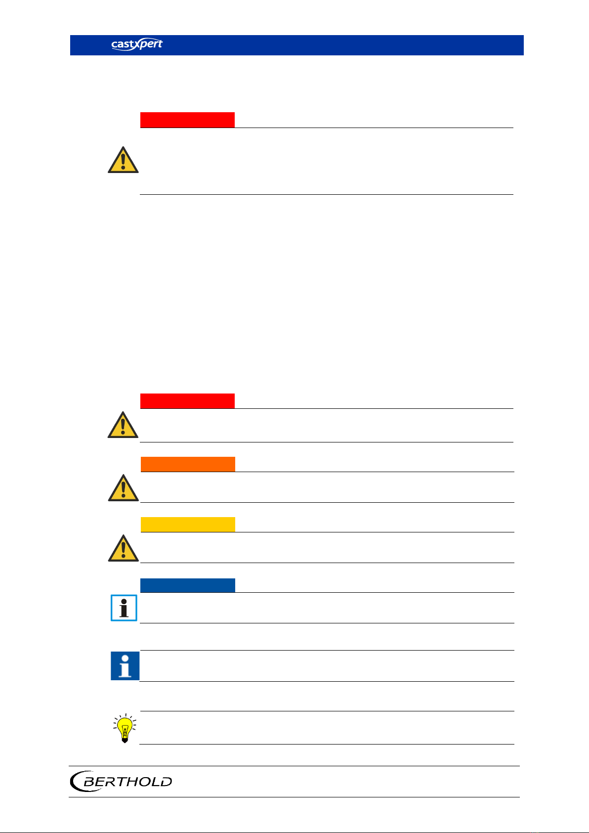
1.9.1 Symbols Used in the Operating Manual
In this manual, warning instructions before instructions for action refer to risks of
injury or damage to property. The hazard-prevention measures described must be
observed.
j
DANGER
Indicates an imminent, major hazard, which will certainly result in serious inju-
ries or even death if the hazard is not avoided.
jWARNING
Indicates a potential
hazard, which can result in serious injuries or even death if
the hazard is not avoided.
j
CAUTION
Refers to a potentially dangerous situation, which can result in medium or mi-
nor physical injuries or damages to property, if it is not avoided.
NOTICE
If this information is not observed, deterioration in the operation and/or prop-
erty damage may occur.
IMPORTANT
Sections marked with this symbol point out important information on the prod-
uct or on handling the product.
Tip
Provides tips on application and other useful information.

1 About this Manual
LB 452
8
47344BA2 Rev.05, 05/2019
1.9.2 Symbols Used on the Device
Read the operating manual
Please observe the instructions in this operating manual.
Electrostatic discharge
Please note
the handling instructions. Electrostatically endangered components.
Please observe the instructions in this operating manual.
Protective earth connection
At this position, connect the protective earth conductor (PE).
Equipotential bonding connection
At this position, connect the equipotential bonding conductor.
Direct voltage
The device is operated with direct voltage and may only be connected with a di-
rect voltage source.
Alternating voltage
The device is operated with alternating voltage and may only be connected
with an alternating voltage source.
No domestic waste
The electric product must not be disposed of in domestic waste.

LB 452
1 About this Manual
47344BA2 Rev.05, 05/2019
9
1.10 Conformity
The company Berthold hereby declares in its sole responsibility that the design of
this product, which is brought to the market by Berthold, complies with relevant
EU directives stated in the original declaration of conformity.
This statement shall become void in the case of changes not authorised by Berthold
or improper use.
For the original declaration of conformity, please refer to Declaration of Conform-
ity in the appendix “Technical Information”.

2 Safety
LB 452
10
47344BA2 Rev.05, 05/2019
2Safety
2.1 Dangers and safety measures
•Read these instructions thoroughly and completely before working with
the product.
•Store the instructions where they are accessible for all users at all times.
2.2 Proper use
The LB 452 evaluation unit (EVU) measures the fill level along with compatible de-
tectors, a compatible radiation source and a compatible radiation source and it
may only be used for this purpose.
The following constitutes proper use:
•Adhering strictly to the instructions and operation sequences and not un-
dertaking any different, unauthorised practices which could endanger your
safety and the operational reliability of the EVU!
•Observing the given safety instructions!
•Carrying out the prescribed maintenance measures or having them carried
out for you!

LB 452
2 Safety
47344BA2 Rev.05, 05/2019
11
Improper use to be prevented:
•If the EVU is used in a way which is not described in the present manual,
the EVU's protection is compromised and the guarantee claim becomes in-
valid.
•Berthold only accepts liability for / guarantees the correspondence of the
EVU to its published specifications.
Avoid the following circumstances:
•Failing to observe the instructions on safety, operation, maintenance and
disposal given in the manual.
•Failure to observe the operating instructions for the EVU and the
GAMMAcast detectors.
•Applying conditions and requirements which do not conform to those
stated in the technical documents, data sheets, operation and assembly in-
structions and other specific guidelines of the manufacturer.
•Using the EVU in a damaged or corroded condition.
•Restructuring or changing the system components.
NOTICE
The device is not approved according to IEC 61508 “Functional safety of safety-
related electric/electronic/programmable electronic systems”.
If the product is used in a way which is not described in the present manual, the
device's protection is compromised and the warranty claim becomes invalid.
BERTHOLD TECHNOLOGIES GmbH & Co. KG shall only accept liability for / guaran-
tee the correspondence of the device to its publicised specifications.
2.4 Qualification of the Personnel
NOTICE
A minimum requirement for all work on or with the product would be employ-
ees with general knowledge who are instructed by an expert or authorised per-
son.
At different parts in this manual, reference is made to personnel with certain qual-
ifications who can be entrusted with different tasks during the installation, usage
and maintenance.
These three groups of people are:
•Those with General Knowledge
•Experts
•Authorised Persons

2 Safety
LB 452
12
47344BA2 Rev.05, 05/2019
Employees with General Knowledge
NOTICE
Employees with general knowledge must always be guided by an expert at the
very least. When dealing with radioactive substances, a radiation safety officer
must also be consulted.
Employees with general knowledge must always be guided by an expert at the very
least. When dealing with radioactive substances, a radiation safety officer must
also be consulted.
Those with a general knowledge are e.g. technicians or mechanics who can under-
take different tasks during the transportation, assembly and installation of the
shielding under the guidance of an authorised person. This can also refer to con-
struction site personnel. The persons in question must have experience in the trans-
portation and assembly of heavy component parts.
Experts
Experts are persons who have sufficient knowledge in the required area due to
their specialist training and who are familiar with the relevant national health and
safety regulations, accident prevention regulations, guidelines and recognised
technical rules.
Expert personnel must be capable of safely assessing the results of their work and
they must be familiar with the content of this manual.
Authorised Persons
Authorised persons are those who are either designated for the corresponding task
due to legal regulations or those who have been authorised by Berthold for par-
ticular tasks. When dealing with radioactive materials, a radiation safety officer
must also be consulted.

LB 452
3 Product Description
47344BA2 Rev.05, 05/2019
13
3Product Description
3.1 Description of the System
The evaluation unit (EVU) consists of a system board (CU Control Unit) with an ex-
works pre-installed basic module (channel 1).
The EVU can be distributed with up to 4 basic modules (channels). This makes the
simultaneous monitoring of 4 mould levels possible.
There is also the possibility of ordering the EVU customised with a pre-installed
extension module or a fieldbus module or installing these modules yourself after-
wards. Further information on the extension module can be found in chapt. 4.3.2
and on the fieldbus module in chapt. 4.4.
You can connect the EVU to both radiometric detectors (GAMMAcast and CON-
GAUGE) and the electromagnetic measurement system (ECcast). When in doubt,
please refer to instruction for the relevant detector type.
3.2 Software
The EVU is delivered with pre-installed software.
The revision status (version) of the software can be seen on the screen display when
starting up the EVU or in the "Channel Setting" menu.
In this manual, the software is described with effect from version 1.5.1 (CU - control
unit, system board) and 1.5.1 (MU - channel).
3.3 Power Supply
The EVU does not have an on and off switch with which the power supply can be
switched on or off. Ensure that the current of the EVU can be simply disconnected
via the external power supply.
3 Product Description
LB 452
14
47344BA2 Rev.05, 05/2019
3.4 Overview
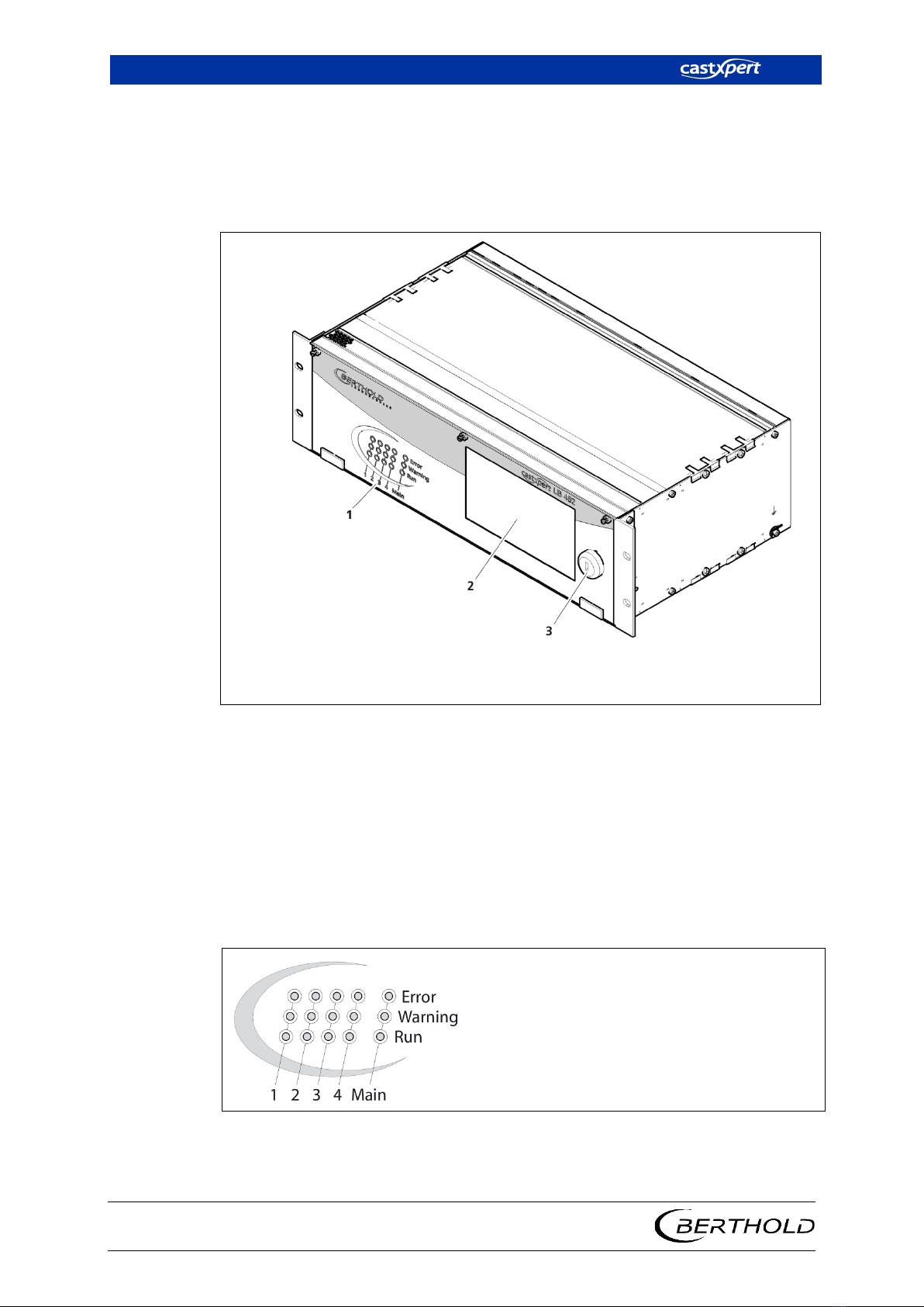
Front View
On the front view of the EVU there are LEDs for displaying each operation mode,
a 7’’ touch display, and a USB port.
1
2
3
Operation mode indicators
7'' Touch display
USB port for the connection of external devices, covered with a protective cap
Fig.1 Front view of the EVU
Control Unit Indicators
The indicators in the "Main" section (control unit) indicate the operation mode of
the EVU. The indicators "1 to 4"(Fig. 2) indicate the operation mode of each meas-
urement channel. This shows which operation mode is active on each measurement
channel.
If an error occurs at just one measurement channel (Error LED lights up), then the
other measurement channels are not affected by this error. The measurement of
other channels continues.
Error
Lights up red in the event of
a device error (chapt. 8.1 Er-
ror Search).
Warning
Lights up yellow if a warning
is present.
Run
Lights up green in error-free
operation
Fig. 2 Control Unit Indicators

LB 452
3 Product Description
47344BA2 Rev.05, 05/2019
15
Error LED
This LED (Fig. 2) lights up if an error has occurred. The actual
measurement is retained. Check the device settings. All
possible error reports are described in chapt. 8
Troubleshooting.
Warning LED
This LED (Fig. 2) lights up if calibration is being carried out or
if the device is in test mode or if any other warning message
is present. The current measurement is retained. All possible
warnings reports are described in chapt. 8 Troubleshooting .
Run LED
This LED (Fig. 2) lights up if the device is in operation and
fault-free. The current measurement is carried out.
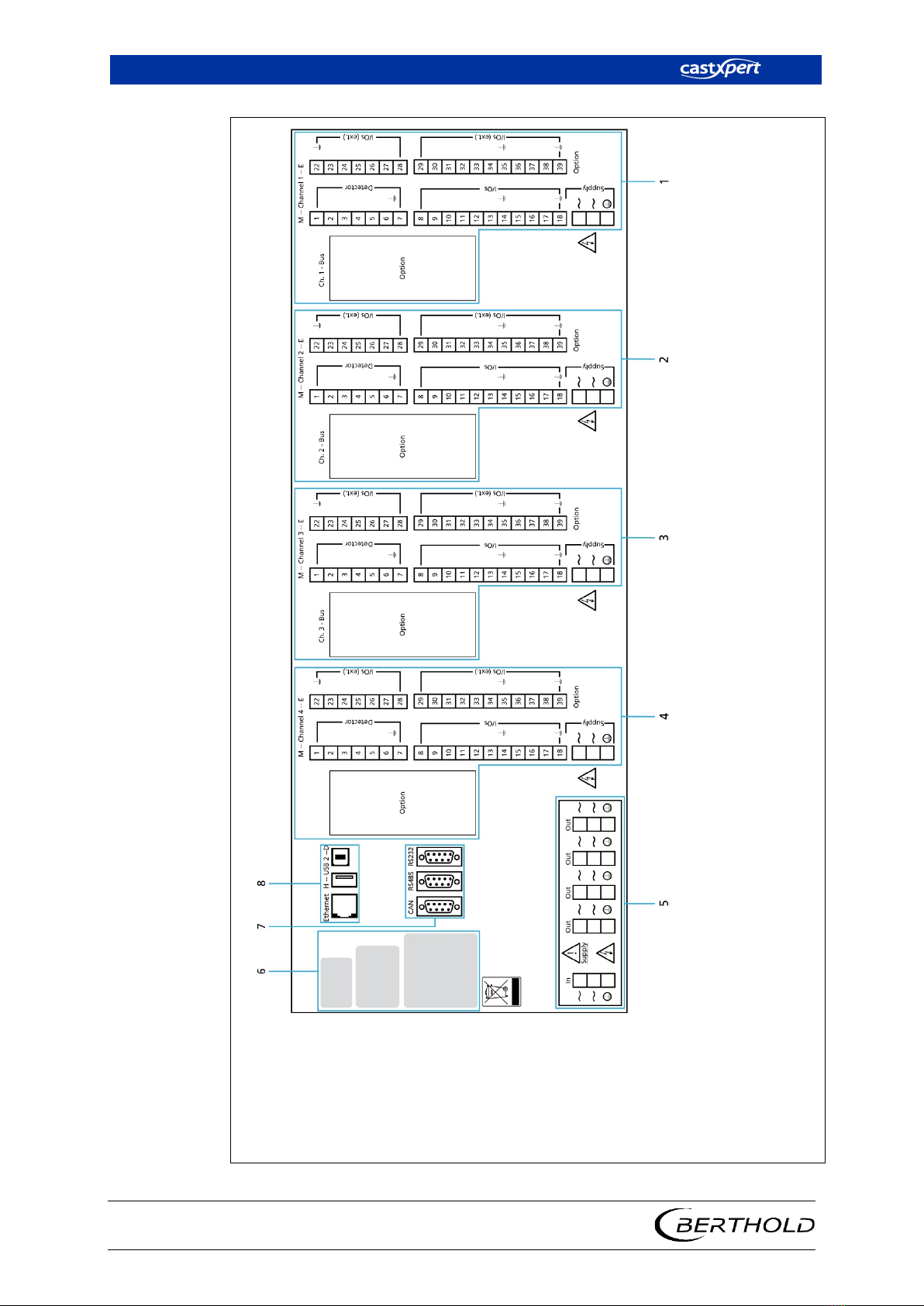
3.4.1 Back View
The following connections are located on the back of the EVU:
•EVU power supply
•Power supply of channels 1 to 4
•Measurement inputs and outputs from the detector for the channels 1 to 4
•Ethernet port for the data transmission via the LAN connection
•USB ports for external USB devices
3 Product Description
LB 452
16
47344BA2 Rev.05, 05/2019
1
2
3
4
5
6
7
8
Slots for channel 1
Slots for channel 2
Slots for channel 3
Slots for channel 4
External power supply of the device (in) and power supply of the channels 1-4 (out)
Type plates
Serial ports (unused)
Ethernet and USB ports
Fig. 3 Back view of the EVU

LB 452
3 Product Description
47344BA2 Rev.05, 05/2019
17
3.5 Radiometric Measurement System
3.5.1 Functional Principle
For the radiometric principle, the weakening of the gamma rays by fluid metal in
the mould is used in order to (Fig. 4, No. 1) measure the fill level in the mould.
The EVU evaluates the electrical signal generated by the detector and continually
measures the fill level of the mould of a casting plant.
NOTICE
Note for casting powder when using GAMMAcast detector!
If casting powder is used for the casting process, note that the height of the cast-
ing powder layer is partially measured via the mould level of the measurement de-
vice. This means that the mould level appears to be somewhat higher than that
corresponding to the actual mould level.
The magnitude of this deviation depends on the height of the casting powder
layer, the bulk density of the casting powder (granulate has a lesser disruptive ef-
fect)
and the casting format. The error is constant and is only a few millimetres for
a desired uniform allocation of casting powder.

3 Product Description
LB 452
18
47344BA2 Rev.05, 05/2019
3.5.2 Measurement System Components/Measurement Setup
The measurement system is made up of the following components:
•castXpert LB 452 evaluation unit (EVU)
•A compatible detector
•Radiation Source/Mould Level Shielding
1
2
3
4
5
6
7
Fill level
Beam path
Measurement line for channel 1
Evaluation unit, back view
Detector
Fluid metal in the mould
Radiation source
Fig. 4 Measurement Set-up

LB 452
3 Product Description
47344BA2 Rev.05, 05/2019
19
NOTICE
Further information on the functional principle of the detectors can be found in
the manual for the corresponding detector type detectors.
Each active measurement channel consists of at least one basic module. This is in-
dispensable for operating the EVU.
The following modules can also be installed in the EVU:
Extension Module
Offers an extra current output, a pulse output, two digi-
tal inputs, and 2 alarm relays.
Fieldbus Module
For transmitting measurement-related data via an RS-485
port (Profibus DP) or an RJ-45 Ethernet port
(Profinet IO).
Further instructions on the extension module can be found in chapt. 4.3.2 and on
the fieldbus module in chapt. 4.4.
4 Start-Up
LB 452
20
47344BA2 Rev.05, 05/2019
4Start-Up
The Start-Up chapter explains how to:
•install the device
•use a terminal box
•configure the current output on the basic module
or on the extension module
•communicate via the fieldbus module
•install an SD Card
4.1 Installation of the Evaluation Unit (EVU)
j
DANGER
Danger to life from electric shock!
uInstallation may only be carried out by a qualified electrician.
uInstallation may only be carried out if the device has been de-energised.
uOnly open the device when free of voltage.
In case of an electric shock, carry out first aid measures and immediately call an
emergency service.
NOTICE
Damage to the device or wrong measurement results!
Error in the calibration or in the setting of parameters.
uWrong measurement results.
uLoss of production.
uDamage in the system.
In general, we would recommend that you have the start-up carried out by the
service of the company Berthold.
IMPORTANT
When operating the EVU, you must adhere to the manual "Mould Level
Shieldings".
Berthold recommends building a separate power connection for each meas-
urement channel (Fig. 3).
Other manuals for castxpert LB 452
2
Table of contents
Other Berthold Control Unit manuals

Popular Control Unit manuals by other brands


Alarmcom
Alarmcom Building36 Smart Water Valve product manual

SIGMA TEK
SIGMA TEK S-DIAS PS 101 instruction manual

Blue Technix
Blue Technix CM-BF537E Hardware user manual

SMART-AVI
SMART-AVI SMTCP-2 user manual

SPX FLOW
SPX FLOW Waukesha Cherry-Burrell D4 Series instruction manual

Tripp Lite
Tripp Lite Power Accessory Module PAM-2 owner's manual