9
PRESTART TESTS
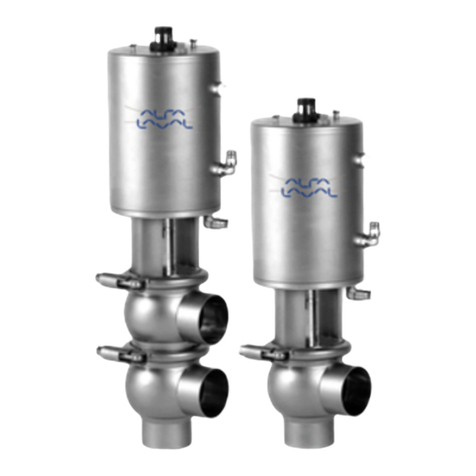
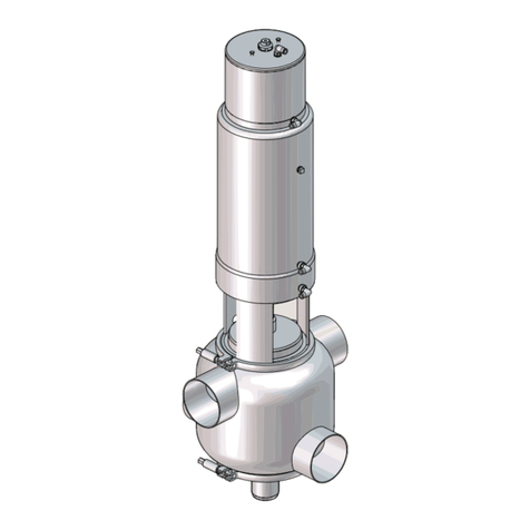
Before putting the Flo-Diversion Valve into operation it is necessary to check the installation. To make
sure that all parts of the system are functioning properly, the following checklist should be used.
1. Air Supply. Make sure all air line connections are tight and free of leaks. Before turning on the air
supply, loosen the adjusting screw on top of the Filter-Regulator until an compression on the spring
is released. Turn on the air supply and turn the adjusting screw in until the pressure guage registers
the air pressure indicated on the data plate.
2. Electrical Wiring. Check the wiring against the schematic included with the control panel to make
sure wiring is complete and all connections are tight. Cheek the voltage ratings on all
components to be sure that they are compatible.
3 Mechanical.
A. Turn the controller on, but do not turn the timing pump on. Turn the selector switch on the
control panel to the “Clean” position. The cam timer (CTl) in the control panel should start
rotating. Thedivertvalvewillmovetotheforwardflowpositioninapproximatelythirty-five
seconds,andtheleakdetectorvalvewillmovetoforwardflowapproximatelytwentyseconds
afterthe divertvalve has been positioned. If the panel also contains aten minuteCIP delay
timer, the timer will time out after ten minutes, then the cam timer will start and operate as
describedabove. Camtimerwill make one revolution every four minutes. Turn the selector
switch to the “product” position. The timer will continue to rotate for as long as four minutes
until the homing cam returns to the start position. The homing cam is the cam on the left side
ofthe timer. The valves will both return immediately to the divert position. Move the selector
switchto the “inspect” position. The valveswill assume the forward flow position.
B. Place the selector switch in the “product” position, and turn on the timing pump. Cam timer
should be in the “home” position to continue these tests. The red indicating light on the STLR
Controller should be on. Set the temperature control to “pasteurize” setting. When pasteurizing
temperatureisreached,thedivertvalvewillassumetheforwardflowposition. Theleakdetector
valvewill be delayed in closing,the timeinterval depending onthe settingof timer(CRTl). The
greenindicator light shouldcomeonandtheredindicatorlightgooffwhenthe divert valve
assumes the forward flow position. If the lights do not function properly, check for microswitch
adjustment. See topic “Adjustments.” Reducing the temperature to sub-legal should cause
bothvalves to assumethe divertposition until temperature is raisedto thepasteurization level at
which time the valves will again operate in the product cycle.
C. Change the selector switch setting from "product" to "clean" while pasteurization temperature is
beingmaintained, and thetiming pumpis on. The valvesshould immediately assumethe divert
position and the timing pump should stop. In 35 seconds, the divert valve should assume
forwardflowposition and twenty seconds later the leakdetectorvalvewillgointotheforward
position.
D. With the timing pump On, and the product at pasteurization temperature, place the selector
switch in the "product" position. when full forward flow is reached, move the selector switch to
the "inspect" position. The valves should immediately assume the divert position and the timing
pumpshould shutoff. After fifteenseconds, orwhen thetiming pumpstops running,the valves
shouldassumetheforwardflowposition,withthetimingpumpremainingoff.
Note: For installations using the Slick 500, if the Timing Pump Run Down Time exceeds the
pre-programmedtime ofthe UVPROM, anew chip will be requried with the matching
setting before the panel is sealed.
E. Whenthe product is below legal pasteurization temperature andthe timing pumpis on, move
the selector switch from "product" position to "clean" position. The timing pump will shut off and
thevalveswill follow thecleaning cycle aftera delay oftenminutes (CRT5).
PRESTARTING
INSTALLATION
