Berthold Duo Xpert User manual
Evaluation unit
LB 470 Level
Operating Manual
56925BA2
Rev. No.: 03, 11/2017
Embedded software version as of vers. 1.3.0 (CPU) and 1.3.0 (MU)


BERTHOLD TECHNOLOGIES GmbH & Co. KG
Calmbacher Str. 22
75323 Bad Wildbad, Germany
www.berthold.com
Telephone +49 7081 177-0
Fax +49 7081 177-100
industry@berthold.com


LB 470 Level Table of Contents
56925BA2 Rev. 03, 11/2017
5
Table of Contents
1About this Operating Manual............................................................................ 7
1.1 16BSome Prior Remarks...................................................................................................... 7
1.2 17BStorage Place ................................................................................................................ 7
1.3 18BTarget Group ................................................................................................................ 7
1.4 19BValidity of the Operating Manual............................................................................... 8
1.5 20BStructure of the Operating Manual ............................................................................ 8
1.6 21BCopyright ...................................................................................................................... 8
1.7 22BRepresentation ............................................................................................................. 8
1.8 23BWarning notes .............................................................................................................. 9
1.8.1 72BSymbols Used in the Operating Manual ..................................................................... 9
1.8.2 73BSymbols Used on the Device ...................................................................................... 11
1.9 Conformity .................................................................................................................. 12
2Safety ................................................................................................................ 13
2.1 Dangers and safety measures .................................................................................... 13
2.2 Proper Use................................................................................................................... 13
2.3 Qualification of the Personnel .................................................................................. 14
2.4 Operator's Obligations............................................................................................... 16
3System Description ........................................................................................... 17
3.1 Overview ..................................................................................................................... 17
3.2 Measuring Principle.................................................................................................... 18
3.3 System Components ................................................................................................... 19
3.3.1 74BSoftware...................................................................................................................... 20
3.3.2 75BFront/rear view master EVU....................................................................................... 21
3.3.3 76BFront/rear view slave module .................................................................................... 24
3.3.4 77BType plate ................................................................................................................... 24
3.4 Measurement arrangements ..................................................................................... 25
3.5 Storage ........................................................................................................................ 25
4Installation........................................................................................................ 29
4.1 General Instructions ................................................................................................... 29
4.2 Unpacking/Scope of Delivery..................................................................................... 29
4.3 Installation variants .................................................................................................... 30
4.3.1 78BInstallation in the wall housing................................................................................. 32
4.3.2 79BInstallation in the 19" subrack .................................................................................. 35
5Electric Installation........................................................................................... 38
5.1 General Instructions ................................................................................................... 38
5.1.180BCircuit Breaker ............................................................................................................ 39
5.1.2 81BCables and Lines ......................................................................................................... 39
5.1.3 82BCable Glands and Blanking Elements........................................................................ 40
5.1.4 83BProtective earth and equipotential bonding ........................................................... 41
5.1.5 EIA-485 (RS-485) Network.......................................................................................... 41
5.2 Electric connection in the wall housing.................................................................... 42
5.3 Electrical connection in a 19"subrack with terminal board.................................... 44
5.4 Terminal board master/master .................................................................................. 47
5.5 Terminal board master/slave ..................................................................................... 49
5.6 Electrical connection in the 19″subrack with clamp block ..................................... 52
5.6.1 84BAssignment terminals master/slave plug .................................................................. 54
5.6.2 85BAssignment clamp block master EVU........................................................................ 55
5.6.3 86BAssignment clamp block slave module ..................................................................... 56
6Operation of the Software............................................................................... 57
6.1 System start................................................................................................................. 57
6.2 EVU standard display ................................................................................................. 58

Table of Contents LB 470 Level
6
56925BA2 Rev. 03, 11/2017
6.3 Navigation................................................................................................................... 58
6.3.1 Diagram display.......................................................................................................... 59
6.4 Status messages .......................................................................................................... 59
6.4.1 87BEvent reports............................................................................................................... 60
6.5 Input field ................................................................................................................... 61
7Main Menu Device Setup ................................................................................. 62
7.1 Menu identification.................................................................................................... 63
7.1.1 88BLocation....................................................................................................................... 64
7.1.2 89BDevice information..................................................................................................... 65
7.2 Menu Access................................................................................................................ 67
7.3 Menu Setup................................................................................................................. 69
7.3.1 90BSystem (Date / Time, Interfaces, Units, Network, Reset).......................................... 69
7.3.2 91BSensors......................................................................................................................... 81
7.3.3 92BCalibration ................................................................................................................ 100
7.3.4 93BMeasurement............................................................................................................ 125
7.3.5 94BSignal Condition ....................................................................................................... 127
7.3.6 95BInputs......................................................................................................................... 132
7.3.7 96BOutputs ..................................................................................................................... 135
7.3.8 97BAlarms ....................................................................................................................... 143
7.3.9 98BSimulation ................................................................................................................. 147
7.4 Menu Backup/Restore .............................................................................................. 151
7.4.1 Backup....................................................................................................................... 151
7.4.2 100BRestore ...................................................................................................................... 153
8Main Menu Diagnostics.................................................................................. 154
8.1 Transmitter Temperature......................................................................................... 154
8.2 Events ........................................................................................................................ 155
8.2.1 101BEVUEEEEVU event Log .......................................................................................................... 155
8.2.2 102BTransm. Event Overview .......................................................................................... 157
8.3 Change Log............................................................................................................... 158
8.4 Menu Data Log ......................................................................................................... 159
8.5 Export service data ................................................................................................... 161
9Troubleshooting ............................................................................................. 162
9.1 Error Search............................................................................................................... 162
9.2 Error Codes of the Evaluation Unit ......................................................................... 164
9.2.1 103BSystem ....................................................................................................................... 164
9.2.2 104BApplication................................................................................................................ 166
9.2.3 105BDetector .................................................................................................................... 167
9.2.4 106BRS 458 Interface ........................................................................................................ 167
9.2.5 107BProcess Connection................................................................................................... 167
10 Maintenance and Repair ................................................................................ 169
10.1 Replacing of Fuses .................................................................................................... 170
10.2 Cleaning .................................................................................................................... 173
11 Decommissioning............................................................................................ 174
11.1 Decommissioning wall housing............................................................................... 175
11.2 Decommissioning 19" subrack................................................................................. 176
11.3 Disposal of Measurement System............................................................................ 177
12 Appendix......................................................................................................... 178
12.1 Setup Protocol .......................................................................................................... 178

LB 470 Level 1 About this Operating Manual
56925BA2 Rev. 03, 11/2017
7
1About this Operating Manual
1.1 16BSome Prior Remarks
The product is handed over to you by the manufacturer BERTHOLD TECHNOLOGIES
GmbH & Co. KG (designated as BERTHOLD in the following) in a complete and
functionally reliable condition.
This operating manual illustrates how to:
•set up/install the product
•make electrical connections
•perform measurements
•apply software settings
•Install the extension module (optional)
•carry out maintenance on the product
•fix errors
•disassemble the product
•dispose of the product.
Read these instructions thoroughly and completely before working with the prod-
uct. We have tried to compile all information for safe and proper operation for
you.
However, should questions arise which are not answered in this operating manual,
please refer to BERTHOLD.
1.2 17BStorage Place
This operating manual as well as all product-related documentation relevant to the
respective application must be accessible at all times near the device.
1.3 18BTarget Group
This operating manual is directed at qualified specialist personnel who are familiar
with handling electrical and electronic assemblies as well as with communication
and measuring techniques.
Specialist personnel refers to those who can assess the work assigned to them and
recognise possible dangers through their specialist training, knowledge and expe-
rience as well as knowledge of the relevant regulations.
1 About this Operating Manual LB 470 Level
8
56925BA2 Rev. 03, 11/2017
1.4 19BValidity of the Operating Manual
The operating manual is valid from the delivery of the Berthold product to the user
until its disposal. Version and release date of this operating manual can be found
in the bottom of each page. Modification services are not performed by the man-
ufacturer BERTHOLD.
The manufacturer reserves the right to make changes to this operating manual at
any time without stating reasons.
NOTICE
The current revision of this operating manual replaces all previous versions.
1.5 20BStructure of the Operating Manual
This operating manual has been divided into chapters. The series of chapters should
help you to familiarise yourself quickly and properly with the operation of the
product.
1.6 21BCopyright
This operating manual contains copyright-protected information. None of the
chapters may be copied or reproduced in any other form without prior authorisa-
tion from the manufacturer.
1.7 22BRepresentation
Identifier
Meaning
Example
Quotation mark
Field in the soft-
wareuser interface
"Calibrate"
Vertical line
Path specification Settings | Selection
Pointed brackets
Keys and buttons
<Update>
Round brackets
Image reference Connect the plug (fig. 1,
item 1)
In the software description, the term "clicking" is used if a process is to be acti-
vated. This also refers to the pressing of a button or an area on the touch display
if a mouse is not used for control.

LB 470 Level 1 About this Operating Manual
56925BA2 Rev. 03, 11/2017
9
1.8 23BWarning notes
Warning notes are designed as follows:
Signal Word
Source and consequence
Explanation, if required
Prevention
In case of emergency
•Warning symbols: (warning triangle) draws attention to the hazard.
•Signal word: Indicates the severity of danger.
•Source: Specifies the type or source of danger.
•Consequence: Describes the consequences of non-compliance.
•Prevention: Specifies how the hazard can be avoided.
•In case of emergency: Specifies which actions are required in the event of
the occurrence of risk.
1.8.1 72BSymbols Used in the Operating Manual
In this manual, warning instructions before instructions for action refer to risks of
injury or damage to property. The hazard-prevention measures described must be
observed.
jDANGER
Indicates an
imminent
, major hazard, which will certainly result in serious in-
juries or even death if the hazard is not avoided.
j
WARNING
Indicates a
potential
hazard, which can result in serious injuries or even death
if the hazard is not avoided.
jCAUTION
Refers to a
potentially dangerous
situation, which can result in medium or
minor physical injuries or damages to property, if it is not avoided.

1 About this Operating Manual LB 470 Level
10
56925BA2 Rev. 03, 11/2017
NOTICE
If this information is not observed, deterioration in the operation and/or prop-
erty damage may occur.
IMPORTANT
Sections marked with this symbol point out important information on the
product or on handling the product.
Tip
Provides tips on application and other useful information.

LB 470 Level 1 About this Operating Manual
56925BA2 Rev. 03, 11/2017
11
1.8.2 73BSymbols Used on the Device
Read the operating manual
Please observe the instructions in this operating manual.
Electrostatic discharge
Please note the handling instructions. Electrostatically endangered compo-
nents. Please observe the instructions in this operating manual.
Protective earth connection
At this position, connect the protective earth conductor (PE).
Equipotential bonding connection
At this position, connect the equipotential bonding conductor.
Direct voltage
The device is operated with direct voltage and may only be connected with a
direct voltage source.
Alternating voltage
The device is operated with alternating voltage and may only be connected
with an alternating voltage source.
No domestic waste
The electric product must not be disposed of in domestic waste.

1 About this Operating Manual LB 470 Level
12
56925BA2 Rev. 03, 11/2017
1.9 Conformity
The company BERTHOLD hereby declares in its sole responsibility that the design
of this product, which is brought to the market by BERTHOLD, complies with rele-
vant EU directives stated in the original declaration of conformity.
This statement shall become void in the case of changes not authorised by
BERTHOLD or improper use.
For the original declaration of conformity, please refer to Declaration of Conform-
ity in Technical Information.

LB 470 Level 2 Safety
56925BA2 Rev. 03, 11/2017
13
2Safety
2.1 Dangers and safety measures
•Read these instructions thoroughly and completely before working with the
product.
•Store the instructions where they are accessible for all users at all times.
2.2 Proper Use
The evaluation unit DuoXpert LB 470 (EVU) measures the level together with com-
patible detectors and an appropriate radiation source and may only be used for
this purpose.
The following constitutes proper use:
•Adhering strictly to the instructions and operation sequences and not un-
dertaking any different, unauthorised practices which could endanger your
safety and the operational reliability of the EVU!
•Observing the given safety instructions!
•Carrying out the prescribed maintenance measures or having them carried
out for you!
•Only use accessories and spare parts from BERTHOLD.

2 Safety LB 470 Level
14
56925BA2 Rev. 03, 11/2017
Improper use to be prevented:
•Failing to observe the specified safetyinstructions and instructions for the
operation, maintenance and disposal in the operating manual.
•Any non-compliance with the present operating manual for the supplied
products.
•Applying conditions and requirements which do not conform to those
stated in the technical documents, data sheets, operation manuals and as-
sembly instructions and other specific guidelines of the manufacturer.
•Use of the product if parts of it are damaged or corroded. This also applies
for seals and used cables.
•Restructuring or changing the system components.
•The product is not suitable for use in potentially explosive areas and may
therefore not be operated in such areas. The product is not explosion-proof.
•Operation ...
oin a state where live parts are accessible.
oin a wall housing with inadequately sealed glands and / or insufficiently
tightened or damaged cable glands.
•Operation without the safety precautions provided by the manufacturer.
•Manipulation or avoidance of existing safety equipment.
BERTHOLD shall only accept liability for / guarantee the correspondence of the de-
vice to its publicised specifications.
If the product is used in a way which is not described in the present operating
manual, the device's protection is compromised and the warranty claim becomes
invalid.
NOTICE
The device is not approved according to IEC 61508 “Functional safety of safety-
related electric/electronic/programmable electronic systems”.
2.3 Qualification of the Personnel
NOTICE
A minimum requirement for all work on or with the product would be employ-
ees with general knowledge who are instructed by an expert or authorised
person.
At different parts in this operating manual, reference is made to groups of people
with certain qualifications who can be entrusted with different tasks during instal-
lation, operation and maintenance.
These three groups of people are:
•Employees with General Knowledge
•Experts
•Authorised Persons.

LB 470 Level 2 Safety
56925BA2 Rev. 03, 11/2017
15
Employees with General Knowledge
NOTICE
Employees with general knowledge must always be guided by an expert at
the very least. When dealing with radioactive substances, a radiation safety
officer must also be consulted.
Employees with general knowledge are e.g. technicians or welders, who can un-
dertake different tasks during the transportation, assembly and installation of the
product under the guidance of an authorised person. This can also refer to con-
struction site personnel. The persons in question must have experience in handling
the product.
Experts
•Experts are persons who have sufficient knowledge in the required area due
to their specialist training and who are familiar with the relevant national
health and safety regulations, accident prevention regulations, guidelines
and recognised technical rules.
•Expert personnel must be capable of safely assessing the results of their
work and they must be familiar with the content of this operating manual.
Authorised Persons
Authorised persons are those who are either designated for the corresponding task
due to legal regulations or those who have been authorised by BERTHOLD for par-
ticular tasks. When dealing with radioactive materials, a radiation safety officer
must also be consulted.

2 Safety LB 470 Level
16
56925BA2 Rev. 03, 11/2017
2.4 Operator's Obligations
The operator of the product must regularly train his personnel in the following
topics:
•Observation and use of the operating manual and the legal provisions.
•Intended operation of the product.
•Observation of the plant security instructions and the operating instructions
of the operator.
•Regular monitoring/maintenance of the product.

LB 470 Level 3 System Description
56925BA2 Rev. 03, 11/2017
17
3System Description
3.1 Overview
The level measuring device LB 470 is an industrial measuring system for the con-
tactless and continuous determination of the level of a product in a container.
A complete measuring system consists of the following components:
•Evaluation unit DuoXpert LB 470
•Source
•Shields
•Point detector / rod detector(s)
These instructions concern the operation of the evaluation unit DuoXpert LB 470
(Fig. 1, item 6). The operation of other system components is part of the independ-
ent instructions of the respective system components.
The EVUs are standard equipment in switch rooms with 19" subracks or switch-
boards.
1
2
3
4
5
6
7
Point source shield
Mounting base
Radiation beam
Rod detector
Measurement line to master EVU
Master EVU
Product
Fig.
1 Example measurement arrangement

3 System Description LB 470 Level
18
56925BA2 Rev. 03, 11/2017
3.2 Measuring Principle
Gamma radiation is used to penetrate a medium in a container. The attenuation
of the radiation is analysed to measure the level in the container.
The evaluation DuoXpert LB 470 (master EVU) is used for the evaluation, transmis-
sion and visualisation of measured values which it receives from the connected
detectors.
The EVU is an independent measurement channel. If several measurement chan-
nels are required, an independent EVU must be used for each channel.
For covering larger measuring ranges with level measurements, it is possible to
connect multiple detectors on a level measuring device LB 470. To do this, an addi-
tional slave module is required (optional) for each additional detector after the
first. A maximum of 16 slave modules can be connected per master EVU. A cascaded
measurement system with a maximum of 17 detectors can be set up in this way.
Tip
Further information on the functional principle of the detectors can be found
in the operating manual.
LB 470 Level 3 System Description
56925BA2 Rev. 03, 11/2017
19
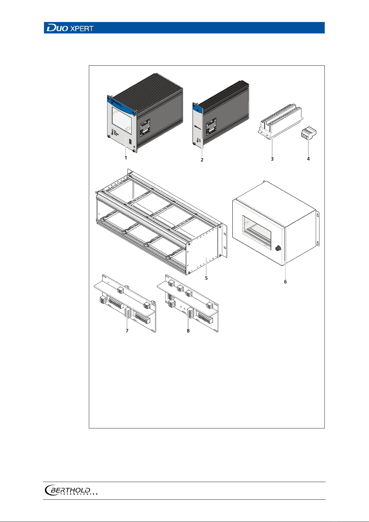
3.3 System Components
1
2
3
4
5
6
7
8
Master-EVU with wide range supply (100-240V AC, 50/60 Hz)
Alternatively: Master-EVU with 24V supply (18-32V DC)
Slave module with wide range power supply (optional)
Alternatively: Slave module with 24V supply (optional)
Clamp block for electrical connections (optional)
only for installation in subrack / switchboard)
Master/Slave connector
19" subrack (optional)
Wall housing (optional)
Backplane Master-Master with cover
Backplane Master-Slave with cover
Fig.
2 System components

3 System Description LB 470 Level
20
56925BA2 Rev. 03, 11/2017
3.3.1 74BSoftware
The EVU is delivered with pre-installed software. The revision status (version) of
the software can be seen on the screen display when starting up the EVU or in the
menu "Device information" (Chapt. 7.1.2 ).
This operating manual describes the software version 1.3.0
(Control Unit / CU) and 1.3.0 (Measurement Unit / MU).
Table of contents
Other Berthold Control Unit manuals

Popular Control Unit manuals by other brands


Profort
Profort multiGuard Master IO Start-up

Yoshitake
Yoshitake GP-1200 Installation and operation manual

Watson McDaniel
Watson McDaniel HSP Series Installation & maintenance manual

ALM
ALM O/A/x2 Operation manual

Smarteh
Smarteh Longo Modbus Products LMP-1.CA1M user manual

Samson
Samson 3251-E Mounting and operating instructions


