Berthoud APOLO 600 User manual

1
APOLO 600
375.418 B English
To be kept for future consultation 03/98

2
3
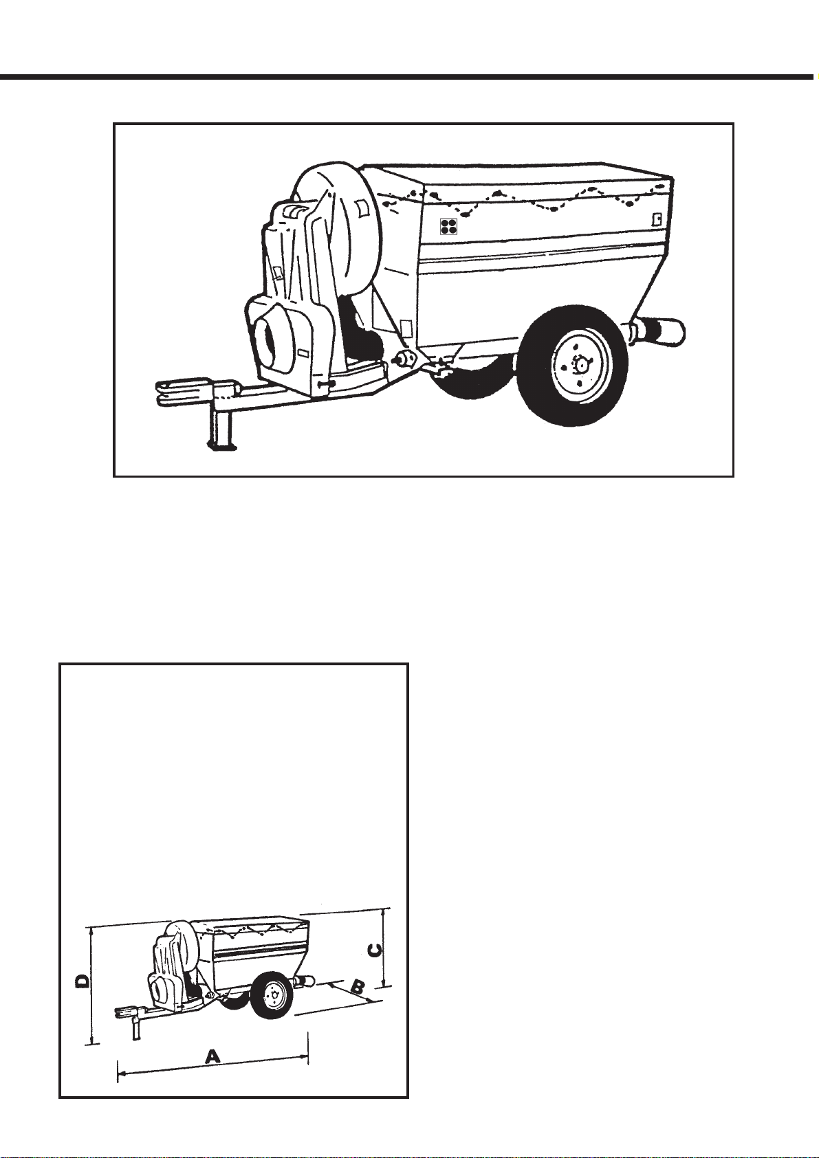
TECHNICAL DATA
CHASSIS : Steel profile and plate.
HOPPER : Sheet plate, 600 litres capacity, large
opening closed by a tilt.
MECHANISM : Speed multiplier with POLY-V
drive belt.
FEEDING:2disengageablearchemediansscrew
driven by a hydraulic motor.
Speed adjustment by flow regulation.
Thissystemensuresperfectevennessofpowder
distribution.
The powder runs directly on to the distribution
blade.
No risk of the turbine, ventilation cage or caisson
becoming clogged..
.
FAN : Aluminium.
Speed of rotation : 4.650 rpm.
DISTRIBUTION : Through two swivelling blades
with adjustable treatment device for the first row.
MIXER : Anti-vault device using 2 vibrating
partitions (BERTHOUD patent).
SPACE REQUIREMENTS
AND WEIGHT
Length (A) 2,00 m
Width (B) 0,92 m
Hopper height (C) 1,08 m
Overall height 1,13 m
Weight empty 267 kg
Gross vehicule weight 720 kg
APOLO 600

4
WARNING
Successful treatment depends on correct
operation of your duster.
Correct operation depends on precise
calibration of the equipment, and this requires
careful checking.
When this checking has been undertaken, the
duster must be commissioned correctly, this
also being necessary for correct spraying and
operation.
Finally,tobecertain thatyourdustercangiveyou
the performance you expect, for a long time,
make sure that you undertake the maintenance
operations required.
CHECKING, STARTING-UP,
OPERATION, MAINTENANCE
are therefore essential operations, and you have
every reason to carefully read the details in this
booklet.
"This duster has been manufactered using
materials which withstand most plant protection
chemicals currently available on the market.
Nevertheless, BERTHOUD cannot assume
responsibility for any damage resulting from an
incompatibilitty of the crop protection chemicals
or product mixtures with the plastic materials:
(polyethylene, polyvinyl chloride, polypropylene,
Vitton, nitrile polyamide)."
PRECAUTIONS WHEN WELDING
When electric arc welding operations are
undertakenonyoursprayeritisOBLIGATORYto
disconnect all electrical boxes ; if this is not done
the electronic components may be destroyed,
and the guarantee is null and void.
Each time a connecting box is repaired, it should
be given a coat of KF 1280 insulating varnish.
5
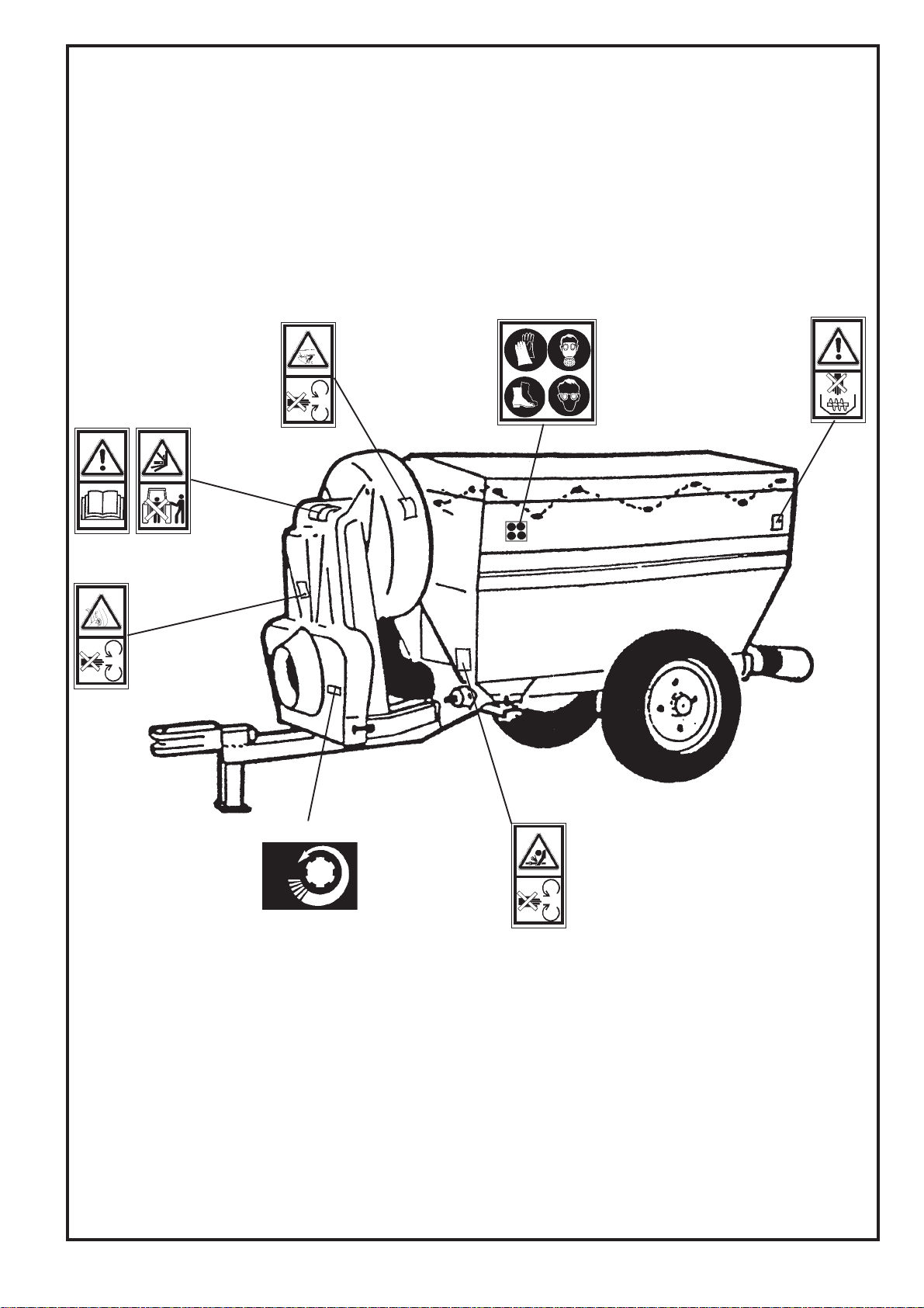
- APOLO 600 -
POSITIONS OF THE SAFETY STICKERS
417.572 417.579
417.590
418.630
It is very important to keep the safety stickers in location and in
good condition as they draw your attention to possible dangers
and refer to the operator's manual.
Seethefollowingpagesandcheck their location on the sprayer.
417.583
417.588
417.577
417.587
540
Tmin
Rmin
Umin
Gmin
Table of contents


