BESA Vega TS-12 User manual

www.vega-absolute.ru
NETWORK TESTER
VEGA TS-12
User Manual
User Manual contains information how to work with
LoRaWAN™ network autonomic tester Vega TS-12, and
also contains warranty terms and conditions and rules
for operating, storage and transportation
www.vega-absolute.ru

www.vega-absolute.ru
Document information
Title
Network tester Vega TS-12
Document type
Manual –translation from Russian
Document number
V02-TS12-01
Revision and date
02 –08 October 2019
This document applies to the following products:
Product name
Type number
End devices
Vega TS-12
Revision history
Revision
Date
Name
Comments
01
06.11.2018
КЕV
Document creation date
02
08.10.2019
KEV
Specified port, on which the device transmits data

Vega TS-12 / User Manual
2
Revision 02 - 08 October 2019
CONTENT
1 DESCRIPTION AND OPERATION ........................................................................................................................................... 3
2 SPECIFICATION............................................................................................................................................................................ 5
3 FAST NETWORK TESTING ........................................................................................................................................................6
4 DEVICE OPERATING................................................................................................................................................................... 7
User interface ............................................................................................................................................................................... 7
Work screen 1 –Uplink and Downlink demodulation margin ...................................................................................8
Work screen 2 –Full information about the network ................................................................................................ 12
Work screen 3 –Downlink signal RSSI and Uplink demodulation margin diagrams......................................15
Work screen 4 –Satellite positioning ............................................................................................................................... 17
Settings ........................................................................................................................................................................................ 20
PIN-code access to settings .................................................................................................................................................23
Automatic test mode .............................................................................................................................................................. 24
Information .................................................................................................................................................................................25
Shutdown.....................................................................................................................................................................................25
Battery charging........................................................................................................................................................................25
Firmware update .......................................................................................................................................................................26
5 COMMUNICATION PROTOCOL ......................................................................................................................................... 28
6 STORAGE AND TRANSPORTATION REQUIREMENTS ................................................................................................ 30
7 CONTENT OF THE PACKAGE................................................................................................................................................31
8 WARRANTY ..................................................................................................................................................................................32

Vega TS-12 / User Manual
3
Revision 02 - 08 October 2019
1 DESCRIPTION AND OPERATION
Tester sends a special signal to the LoRaWAN™ network (‘Uplink’ packet), in response to
which the tester received a confirmation (‘Downlink’ packet).
Tester represents various information about network:
▪«Uplink»frequency –frequency on which the request sent to the network (MHz);
▪«Downlink»frequency - frequency on which the confirmation sent from the
network (MHz);
▪SF (spread factor) - coefficient determining the data rate of «Uplink» and
«Downlink»signals;
▪Tester’s transmitter power (dBm);
▪Requests number;
▪RSSI (Received signal strength indicator) –«Downlink» signal power (dBm);
Network tester Vega TS-12
designed for testing LoRaWAN
networks during its deploying
and setting up

Vega TS-12 / User Manual
4
Revision 02 - 08 October 2019
▪Receiving window number at which confirmation was received (1 or 2);
▪UDM - Uplink demodulation margin (hereinafter UM);
▪DDM - Downlink demodulation margin (hereinafter DM);
▪PER (packet error rate) –relation of the received packets number to the total
number of sending packets expressed as a percentage;
▪Number of visible gateways.
In addition, tester may represent information from navigation satellites:
▪number of visible GPS and GLONASS satellites;
▪LAT / LON –latitude / longitude –coordinates of tester;
▪UTC –current satellites time;
▪ALT –altitude;
▪SATU –number of satellites from which navigation information received;
▪HDOP - horizontal dilution of precision;
▪quality of navigation signal.
Tester powered from rechargeable battery 550 mAh by which tester may work up to 16
hours with disable GNSS transmitter and up to 7 hours with GNSS transmitter turned on.
Tester configured via self-interface ‘Settings’.

Vega TS-12 / User Manual
5
Revision 02 - 08 October 2019
2 SPECIFICATION
Main
Operating temperatures
-40…+85 °С
Display
OLED, 1,3”
USB-port
micro-USB, 5 V, 500 mA
LoRaWAN
LoRaWAN class
А
Supported LoRaWAN channels number
No less than 16
LoRaWAN antenna type
internal
Sensitivity
-138 dBm
Radio coverage in restrained urban conditions
Up to 5 km
Radio coverage within line of sight
Up to 15 km
Transmitter power
Up to 100 mW (configurable)
GNSS
Sensitivity of GNSS transmitter, not less than
-160 dBm
GNSS antenna type
internal
Power
Rechargeable battery
550 mAh
Case
Ingress protection rating
IP64
Housing dimensions
90 х 52 х 31 mm

Vega TS-12 / User Manual
6
Revision 02 - 08 October 2019
3 FAST NETWORK TESTING
Press ‘OK’
button
Waiting for
device loading
Press ‘Up’
button:
The first
pressing –
connection to
the network, the
second –
network test
Gateways
number
Uplink demodulation
margin in dBm
Downlink demodulation
margin in dBm
Successful
transmissions in
percent
No signal / no
data
Press ‘Left’
button for
display switching

Vega TS-12 / User Manual
7
Revision 02 - 08 October 2019
4 DEVICE OPERATING
USER INTERFACE
Tester equipped with control buttons, sound speaker and OLED display. Every pressing
on the button accompaniment with sound signal if device sound is not off.
To common main menu it need to press ‘OK’ button while device is on. Menu appears
independent on what was on the display before button pressing.
‘Right’ and ‘Left’ buttons is using for navigating through the menu. Press ‘OK’ button for
select a menu item. Main menu contains the follow items:
Work screens –screens with the full information about the network.
Settings –tester settings screen.
Information –displays the keys and identifiers of the tester.
Shutdown –choose that item to switch device to low power consumption mode.
Battery charge –battery charge indicator.
Work screens
Information
Shutdown
Settings
Battery charge
Vega TS-12 / User Manual
8
Revision 02 - 08 October 2019
WORK SCREEN 1 –UPLINK AND DOWNLINK DEMODULATION MARGIN
Work screen 2appears just after device switch on. Switching between screens carried out
by pressing ‘Left’and ‘Right’ buttons. During the testing process, you can freely navigate between
them to get more completely information about the network.
For the work screen 1 appearing, you can press ‘Left’ button after device switch on.
Herewith the data is not available on it. Work screen 1 allows you to get the follow information:
▪Number of visible gateways;
▪PER coefficient –percent of successful transmissions;
▪Margin demodulation diagrams and numerical values of UM and DM of the last
session.
Margin demodulation is the positive integer value displayed in dBm and indicating how much
received signal above the demodulation threshold. ‘0’ value means that the packet was received
on the bottom of demodulation (0 dBm), whereas, for example, ‘20’ value means that the packet
was received on 20 dBm above the demodulation threshold.
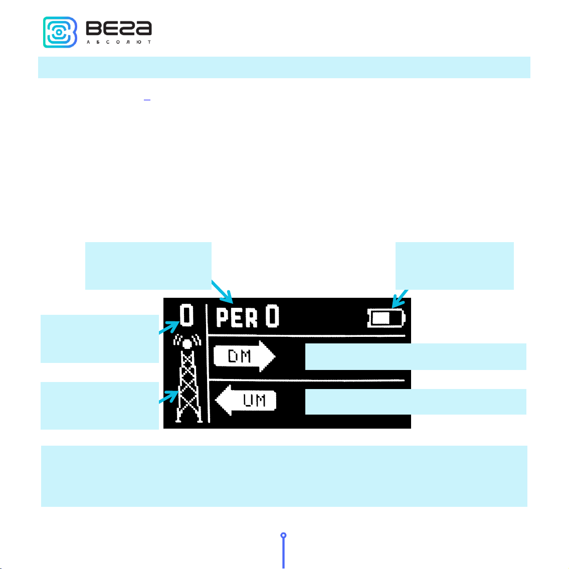
DM –Downlink Margin demodulation
UM –Uplink Margin demodulation
‘Gateway’ icon
Number of
gateways
Percent of successful
transmissions
Battery charge

Vega TS-12 / User Manual
9
Revision 02 - 08 October 2019
from 0 to 5
Communication on the brink of failure, unstable connection to the network
from 5 to 10
Border zone, stable communication is not guaranteed
above 10
Good signal strength, confident communication
‘Gateway’ icon - displays the activity of the communication process as an animation.
Animation continues until the confirmation is accepted or the receiving window timeout expires.
Number of gateways - the number of gateways received the last packet from the network
tester successfully.
Percent of successful transmissions –PER (Packet error rate) coefficient is calculated as
the ratio of the number of confirmations received by the tester from the network to the total
number of requests, expressed as a percentage. It can vary from 0 (no one confirmation has come,
or PER is less than 1% and rounding up to integer) to 100% (the number of confirmations is equal
to the number of requests).
Battery charge –displays the current battery charge status. When the battery is critically
discharged, the icon becomes empty, flashes, and the tester emits a periodic beep. The
approximate remaining time of operation is not more than 5 minutes, it is necessary to charge the
battery.
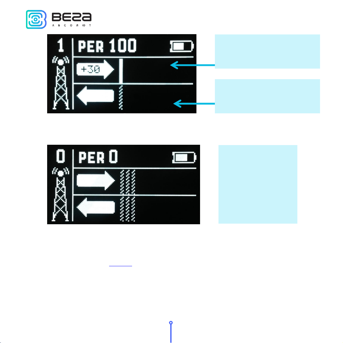
The first time the ‘Up’button is pressed, the tester sends a request to the network to join
the network (hereinafter ‘join-request’), which is displayed on the UM (Uplink demodulation
margin) diagram as a shaded bar. If the tester is successfully connected to the network, a filled bar
appears in the DM diagram (Downlink demodulation margin).
Vega TS-12 / User Manual
10
Revision 02 - 08 October 2019
A shaded bar appears on the DM diagram if a failed attempt is made also. In total, the
network tester takes three attempts to join the network.
After successful joining the network, you can start testing the network. There are two ways:
manual and automatic. In the first case, the network tester sends an Uplink request to the network
each time the ‘Up’ button is pressed. In the automatic mode, the tester will send requests itself
with the period specified in settings, and also by pressing the ‘Up’button.
Connection to the network is
successful –filled bar
Three failed attempts
to join the network
Join-request, is displayed as a
shaded bar

Vega TS-12 / User Manual
11
Revision 02 - 08 October 2019
‘P’ icon –automatic mode indicator is located near the ‘Gateway’ icon. If it is, automatic
test mode is on, if not - off.
Diagrams DM and UM - the arrow indicates the direction of the radio signal propagation,
and the diagram shows the history of its change. The level of each bar on diagram shows the
demodulation margin of a particular packet. The latest (recent) radio communication is displayed
on the bar located next to the arrow. On the arrow is displayed the numerical value of the
demodulation margin in dBm of the latest radio communication. During the execution of new
communications, the diagram shifts to the right.
‘GPS’ icon - satellite positioning function indicator located in upper right screen side. If it is
satellite positioning function is on, if there is no –off.
If the radio communication has not passed or the data has not been received, for example,
an error occurred during reception or the confirmation window timeout expires, the shaded bar
is displayed (that bar type has no level and occupies the entire amplitude of the diagram).
DM diagram
UM diagram
‘GPS’ icon
‘P’ icon
Vega TS-12 / User Manual
12
Revision 02 - 08 October 2019
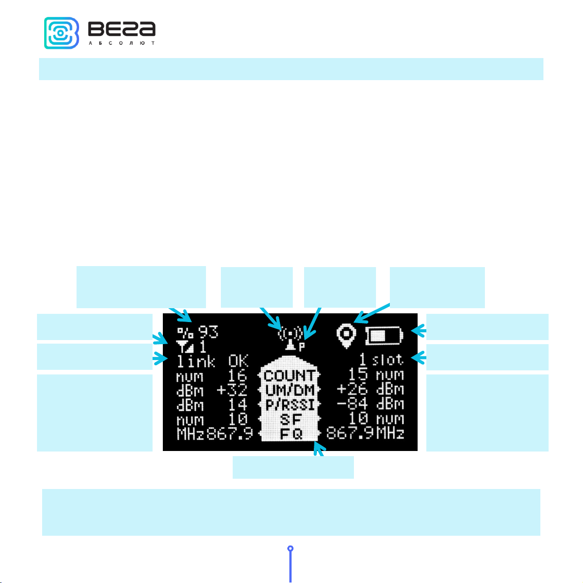
WORK SCREEN 2 –FULL INFORMATION ABOUT THE NETWORK
Work screen 2 allows you to get the following information:
▪PER coefficient –percent of successful transmissions;
▪Number of visible gateways;
▪Tester’s join status;
▪Number of packets transmitted by the tester - COUNT;
▪UM (demodulation margin), P(power), SF (spread factor) and FQ (frequency) of the
latest transmitted packet;
▪Receiving window number of the latest received confirmation - slot;
▪Number of packets received by the gateway - COUNT;
▪DM (demodulation margin), RSSI (signal level), SF (spread factor) and FQ (frequency)
of the latest received packet.
Unlike other screens, the work screen 2 displays information only about the last communication
session. The accumulated data here is the PER coefficient and the total number of received /
transmitted packets.
‘Antenna’
icon
‘Network’ icon
Percent of successful
transmissions
‘GPS’ icon
Status line
Parameters of the
latest packet
transmitted by
tester
Battery charge
Receiving window №
Parameters of the
latest packet
received by tester
Title bar
‘P’ icon

Vega TS-12 / User Manual
13
Revision 02 - 08 October 2019
Percent of successful transmissions –PER (Packet error rate) coefficient is calculated as
the ratio of the number of confirmations received by the tester from the network to the total
number of requests, expressed as a percentage. It can vary from 0 (no one confirmation has come,
or PER is less than 1% and rounding up to integer) to 100% (the number of confirmations is equal
to the number of requests).
‘Network’ icon - has two states: joined / disconnected. Next to the icon, the network
capacity is displayed as a number of gateways that successfully received the latest packet from
the network tester.
Status line –the current transmission status is displayed in text form:
▪join TX –a request to join the network is performed;
▪join RX –reception of confirmation to a network connection request;
▪joined –the connection to the network was successful (the ‘Network’icon changes
its status);
▪link TX –‘Uplink’ request is performed;
▪link RX –reception of confirmation ‘Downlink’;
▪link OK –communication session was successful;
▪time-out –‘Downlink’ packet receiving window timeout expires;
▪error –communication session error.
Parameters of the latest packet transmitted by tester –to the left of the title bar there is
information display from top to bottom in order:
▪COUNT –total number of ‘Uplink’packets transmitted by the tester;
▪UM –demodulation margin of the latest transmitted ‘Uplink’packet;
▪P –power of network tester transmitter;
▪SF –Spread factor –the latest ‘Uplink’ packet transmitting rate indicator;
▪FQ –frequency on which the latest ‘Uplink’ packet transmits.
Title bar –is located in the center of work screen. It is the list of displayed parameters. To
the left of the title bar there is transmitting information displayed, to the right of the title bar there
is reception information.

Vega TS-12 / User Manual
14
Revision 02 - 08 October 2019
Parameters of the latest packet received by tester –to the right of the title bar there is
information display from top to bottom in order:
▪COUNT –total number of ‘Downlink’packets received by the tester;
▪DM –demodulation margin of the latest transmitted ‘Downlink’packet;
▪RSSI –the latest ‘Downlink’ packet power expressed as dBm;
▪SF - Spread factor –the latest ‘Downlink’ packet transmitting rate indicator;
▪FQ - frequency on which the latest ‘Downlink’ packet transmits.
‘Antenna’ icon –is located above the title bar and displays the moments of sending and
receiving packets as an animation.
‘P’ icon –automatic mode indicator is located near the ‘Antenna’ icon. If it is, automatic
test mode is on, if not - off.
‘GPS’ icon - satellite positioning function indicator located in upper right screen side. If it is
satellite positioning function is on, if there is no –off.
Battery charge –displays the current battery charge status. When the battery is critically
discharged, the icon becomes empty, flashes, and the tester emits a periodic beep. The
approximate remaining time of operation is not more than 5 minutes, it is necessary to charge the
battery.
Receiving window №- in the first or second window the latest ‘Downlink’ packet was
received.
Vega TS-12 / User Manual
15
Revision 02 - 08 October 2019
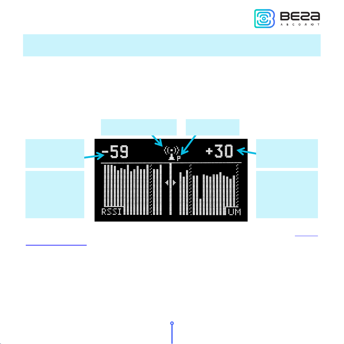
WORK SCREEN 3 –DOWNLINK SIGNAL RSSI AND UPLINK DEMODULATION MARGIN
DIAGRAMS
Work screen 3 allows you to get the follow information:
▪RSSI (Received signal strength indicator) –‘Downlink’ signal power expressed as
dBm;
▪UM - demodulation margin of the latest transmitted ‘Uplink’packet expressed as
dBm;
▪The presence of lost packets.
Please note that screen 3 does not show the battery charge level, and there is no satellite
positioning function indicator. It is not confluence to the function work.
The left side of the screen displays an RSSI diagram, and in the upper left corner the RSSI
value for the last received packet in dBm is shown. When a new packet is received, the diagram
shifts to the left, and the bar corresponding to the last received value appears on the right side.
The right part of the screen displays the ‘Uplink’packet demodulation diagram, and in the
upper right corner the UM value for the last transmitted packet is displayed. When a new packet is
UM as dBm
RSSI as dBm
UM diagram
(Uplink
demodulation
margin)
RSSI diagram
(Downlink
signal power)
‘Antenna’ icon
‘P’ icon

Vega TS-12 / User Manual
16
Revision 02 - 08 October 2019
send, the diagram shifts to the right, and the bar corresponding to the last received value appears
on the left.
If the communication session was successful and the data was received, then the bar on
the diagram is filled with white color, if the session has not passed or the data is not received, then
the bar is shaded.
‘Antenna’ icon - displays moments of transmission and reception of packets as an
animation.
‘P’ icon –automatic mode indicator is located near the ‘Antenna’ icon. If it is, automatic
test mode is on, if not - off.
Vega TS-12 / User Manual
17
Revision 02 - 08 October 2019
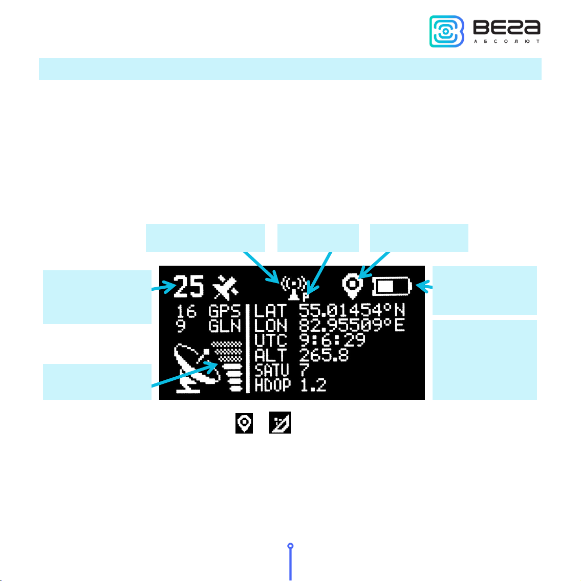
WORK SCREEN 4 –SATELLITE POSITIONING
Work screen 4 allows you to get the follow information:
▪Number of visible satellites GPS and GLN (GLONASS) all and separately;
▪Relative satellite signal level;
▪Tester coordinates LAT (latitude), LON (longitude), expressed in degrees and ALT
(altitude), expressed in meters;
▪UTC –world time in format hh:mm:ss;
▪SATU –satellites number, used to determine current coordinates;
▪HDOP –horizontal dilution of precision.
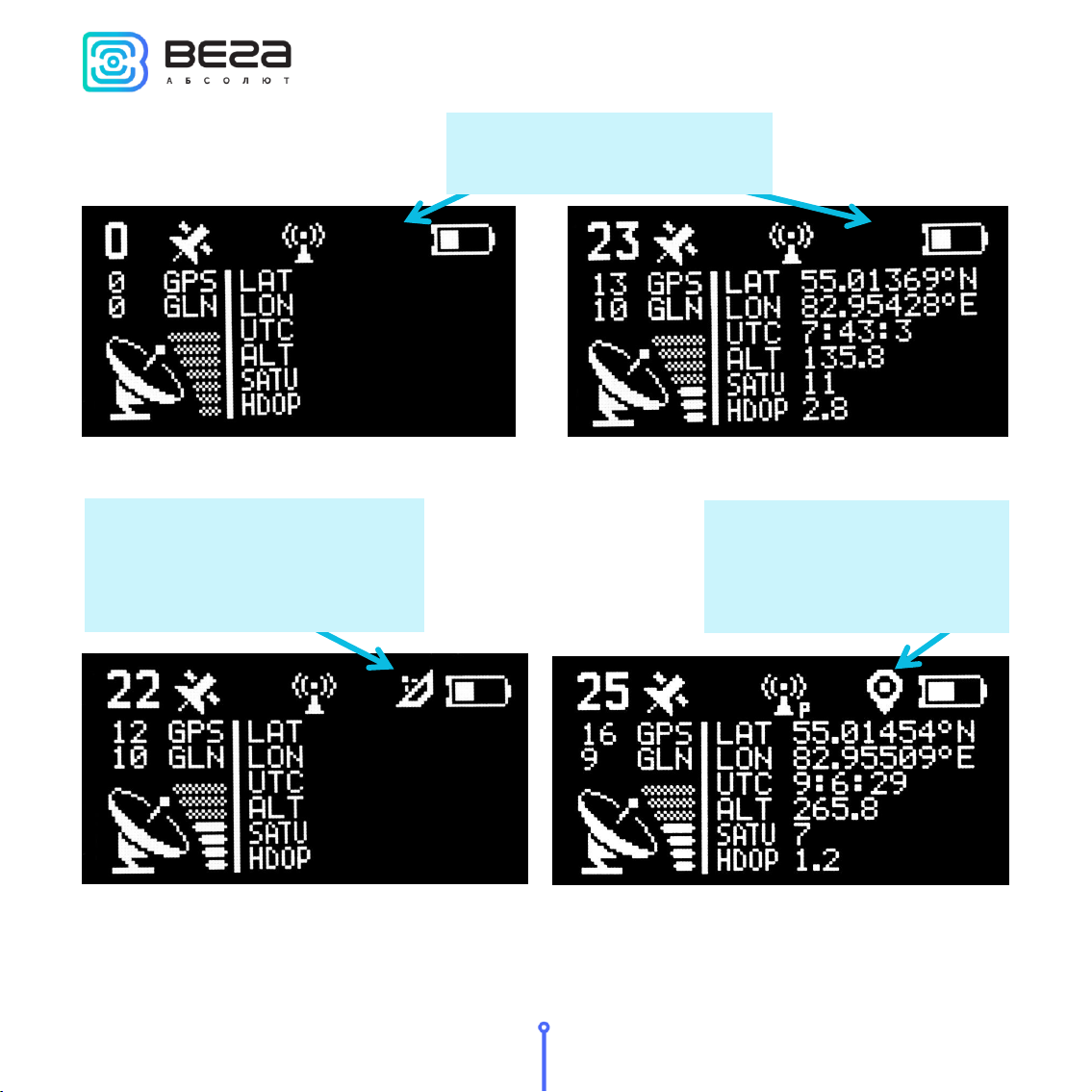
‘GPS’ icon - can take the form or , or absent.
If satellite positioning function switch off there is no any information on work screen 4 in
case of coordinates not determinate after tester last loading or there is a last navigation
information in stable form. ‘GPS’ icon absent in that case and it means that displayed information
not valid.
Basic
information
about
coordinates
‘P’ icon
‘Antenna’ icon
Battery charge
Satellite signal
level
Number of visible
satellites
‘GPS’ icon
Vega TS-12 / User Manual
18
Revision 02 - 08 October 2019
When satellite positioning function is on there are two possible states of ‘GPS’ icon:
‘GPS’ icon absent, - all
information not valid
Searching for satellites and
determining coordinates;
information about the number
of satellites is relevant
Coordinates defined; all
information is current and
update once a second.

Vega TS-12 / User Manual
19
Revision 02 - 08 October 2019
The left side of the screen displays the number of visible satellites and signal level; that
information is valid always during the satellite positioning function is on.
The right side of the screen displays navigation data, coordinates, time, altitude, number
of used satellites and HDOP. That information is valid while there is a icon only, and in that
case the data update once a second.
Battery charge –displays the current battery charge status. When the battery is critically
discharged, the icon becomes empty, flashes, and the tester emits a periodic beep. The
approximate remaining time of operation is not more than 5 minutes, it is necessary to charge the
battery.
‘Antenna’ icon –is located above the title bar and displays the moments of sending and
receiving packets as an animation.
‘P’ icon –automatic mode indicator is located near the ‘Antenna’ icon. If it is, automatic
test mode is on, if not - off.
Table of contents


