Vega VEGAMET 624 User manual

Operating Instructions
VEGAMET 624
4…20 mA/HART signal conditioning instrument
Document ID:
28969
Signal
conditioning instruments
and communication

Contents
1About this document
1.1Function.................................. 4
1.2Target group .............................. 4
1.3Symbolism used............................ 4
2For your safety
2.1Authorised personnel ........................ 5
2.2Appropriate use ............................ 5
2.3Warning about misuse ....................... 5
2.4General safety instructions . . . . . . . . . . . . . . . . . . . . 5
2.5Safety label on the instrument . . . . . . . . . . . . . . . . . . 6
2.6CE conformity ............................. 6
2.7Safety instructions for Ex areas . . . . . . . . . . . . . . . . . 6
2.8Environmental instructions..................... 6
3Product description
3.1Configuration .............................. 7
3.2Principle of operation ........................ 8
3.3Operation................................. 8
3.4Packaging,transport and storage ............... 9
4Mounting
4.1General instructions ......................... 10
4.2Mounting instructions ........................ 10
5Connecting to power supply
5.1Preparing the connection ..................... 12
5.2Connection procedure........................ 12
5.3Wiring plan................................ 14
6Setup with the integrated indicating and adjustment unit
6.1Adjustment system .......................... 16
6.2Setup procedure............................ 17
6.3Menu schematic ............................ 25
7Setup with PACTware
7.1Connecting the PC .......................... 31
7.2Parameter adjustment with PACTware . . . . . . . . . . . . 34
7.3Setup web server/e-mail,remote enquiry . . . . . . . . . . 34
8Application examples
8.1Level measurement in a cylindrical tank with overfill
protection/dry run protection . . . . . . . . . . . . . . . . . . . 36
8.2Pump control 1/2(running time controlled) . . . . . . . . . 37
8.3Tendency recognition ........................ 39
8.4Flow measurement .......................... 40
2VEGAMET 624 •4…20 mA/HART signal conditioning instrument
Contents
28969-EN-091116

9Maintenance and fault rectification
9.1Maintenance .............................. 43
9.2Rectify malfunctions ......................... 43
9.3Instrument repair ........................... 46
10 Dismount
10.1Dismounting steps .......................... 47
10.2Disposal ................................. 47
11 Supplement
11.1Technical data ............................. 48
11.2Overview applications/functionality ............... 52
11.3Dimensions ............................... 53
Supplementary documentation
Information:
Supplementary documents appropriate to the ordered version come
with the delivery.You can find them listed in chapter "Product
description".
VEGAMET 624 •4…20 mA/HART signal conditioning instrument 3
Contents
28969-EN-091116

1About this document
1.1Function
This operating instructions manual provides all the information you
need for mounting,connection and setup as well as important
instructions for maintenance and fault rectification.Please read this
information before putting the instrument into operation and keep this
manual accessible in the immediate vicinity of the device.
1.2Target group
This operating instructions manual is directed to trained qualified
personnel.The contents of this manual should be made available to
these personnel and put into practice by them.
1.3Symbolism used
Information,tip,note
This symbol indicates helpful additional information.
Caution:If this warning is ignored,faults or malfunctions can
result.
Warning:If this warning is ignored,injury to persons and/or serious
damage to the instrument can result.
Danger:If this warning is ignored,serious injury to persons and/or
destruction of the instrument can result.
Ex applications
This symbol indicates special instructions for Ex applications.
lList
The dot set in front indicates a list with no implied sequence.
àAction
This arrow indicates a single action.
1Sequence
Numbers set in front indicate successive steps in a procedure.
4VEGAMET 624 •4…20 mA/HART signal conditioning instrument
1About this document
28969-EN-091116

2For your safety
2.1Authorised personnel
All operations described in this operating instructions manual must be
carried out only by trained specialist personnel authorised by the plant
operator.
During work on and with the device the required personal protective
equipment must always be worn.
2.2Appropriate use
VEGAMET 624 is a universal signal conditioning instrument and power
supply unit for connection of a 4…20 mA/HART sensor.
You can find detailed information on the application range in chapter
"Product description".
Operational reliability is ensured only if the instrument is properly used
according to the specifications in the operating instructions manual as
well as possible supplementary instructions.
For safety and warranty reasons,any invasive work on the device
beyond that described in the operating instructions manual may be
carried out only by personnel authorised by the manufacturer.Arbitrary
conversions or modifications are explicitly forbidden.
2.3Warning about misuse
Inappropriate or incorrect use of the instrument can give rise to
application-specific hazards,e.g.vessel overfill or damage to system
components through incorrect mounting or adjustment.
2.4General safety instructions
This is a high-tech instrument requiring the strict observance of
standard regulations and guidelines.The user must take note of the
safety instructions in this operating instructions manual,the country-
specific installation standards as well as all prevailing safety
regulations and accident prevention rules.
The instrument must only be operated in a technically flawless and
reliable condition.The operator is responsible for trouble-free
operation of the instrument.
During the entire duration of use,the user is obliged to determine the
compliance of the required occupational safety measures with the
current valid rules and regulations and also take note of new
regulations.
VEGAMET 624 •4…20 mA/HART signal conditioning instrument 5
2For your safety
28969-EN-091116

2.5Safety label on the instrument
The safety approval markings and safety tips on the device must be
observed.
2.6CE conformity
This device fulfills the legal requirements of the applicable EC
guidelines.By attaching the CE mark,VEGA provides a confirmation
of successful testing.You can find the CE conformity declaration in the
download area of www.vega.com.
2.7Safety instructions for Ex areas
Please note the Ex-specific safety information for installation and
operation in Ex areas.These safety instructions are part of the
operating instructions manual and come with the Ex-approved
instruments.
2.8Environmental instructions
Protection of the environment is one of our most important duties.That
is why we have introduced an environment management system with
the goal of continuously improving company environmental protection.
The environment management system is certified according to DIN
EN ISO 14001.
Please help us fulfil this obligation by observing the environmental
instructions in this manual:
lChapter "Packaging,transport and storage"
lChapter "Disposal"
6VEGAMET 624 •4…20 mA/HART signal conditioning instrument
2For your safety
28969-EN-091116

3Product description
3.1Configuration
The scope of delivery encompasses:
lVEGAMET 624 signal conditioning instrument
lTerminal socket
lCoded pins and bridges
lRS232 modem connection cable (optional)
lDocumentation
-this operating instructions manual
-Supplementary instruction 30325 "RS232/Ethernet connec-
tion"(optional)
-Supplementary instructions manual 30768 "Modbus-TCP,
VEGA ASCII protocol"(optional)
-Ex-specific"Safety instructions"(with Ex-versions)
-if necessary,further certificates
VEGAMET 624 consists of the components:
lVEGAMET 624 signal conditioning instrument with indicating and
adjustment unit in the front
lTerminal socket
VEGAMET
1 2 3 4
9 10 11 12
17 18 20 21 22
5 6 7 8
13 14 15 16
23 24 25 26 27 28
Ser. No.
12345678
on
OK
ESC
COM
3
2
1
2
3
4
1
6
5
Fig.1:VEGAMET 624
1Ex separating chamber with Ex version
2VEGAMET 624
3Indicating and adjustment unit
4Communication interface for VEGACONNECT (I²C)
5RS232 or Ethernet interface (optional)
6Terminal socket
The type label contains the most important data for identification and
use of the instrument:
lArticle number
lSerial number
lTechnical data
Scope of delivery
Components
Type label
VEGAMET 624 •4…20 mA/HART signal conditioning instrument 7
3Product description
28969-EN-091116

lArticle numbers,documentation
The serial number allows you to access the delivery data of the
instrument via www.vega.com,"VEGA Tools"and "serial number
search".
3.2Principle of operation
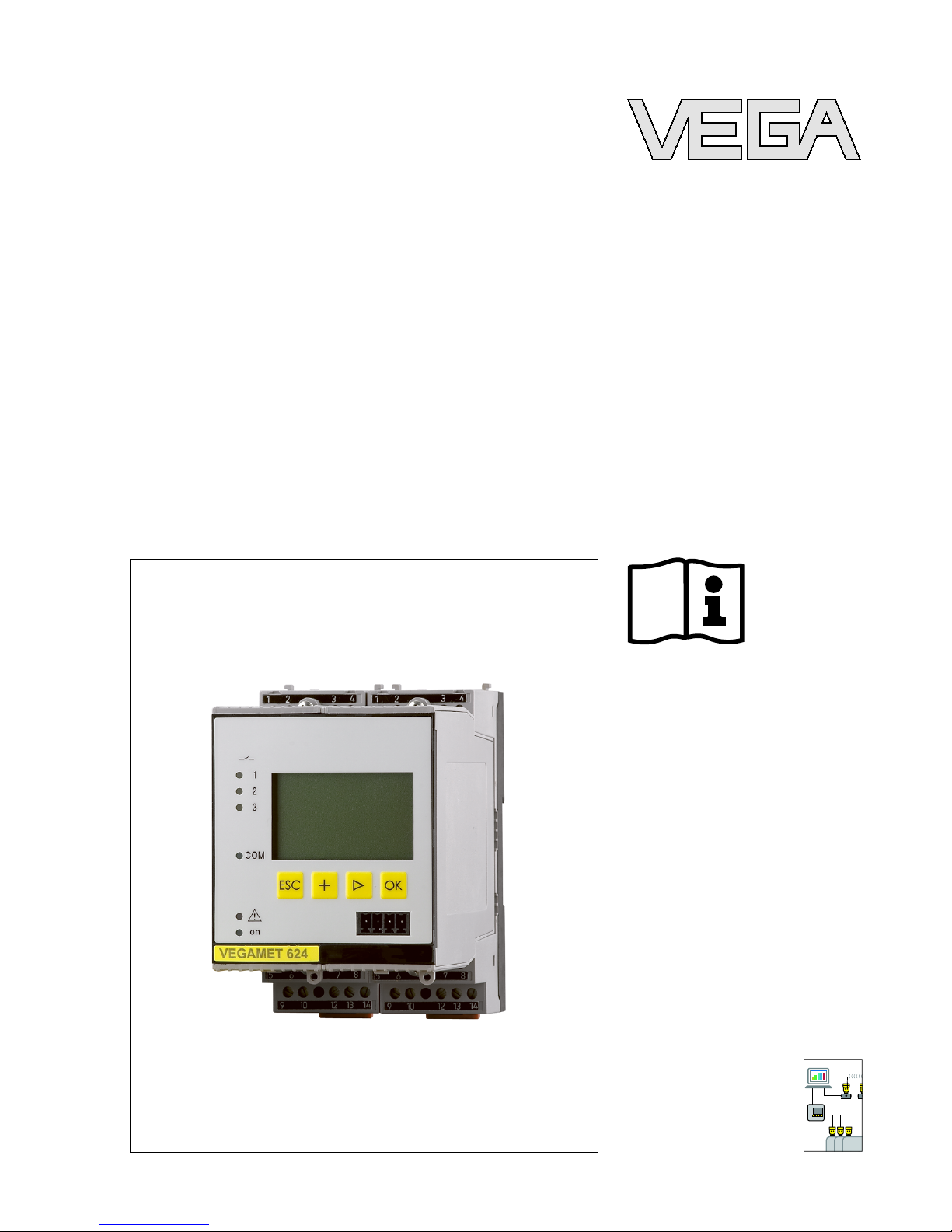
VEGAMET 624 is a universal signal conditioning instrument for a
number of applications such as level,gauge and process pressure
measurement.At the same time,it can serve as power supply unit for
connected sensors.VEGAMET 624 is designed for connection of any
4…20 mA/HART sensor.
On instruments with one of the optional interfaces (RS232/Ethernet),
the measured values can be retrieved via modem or network and
displayed by means of a web browser or WEB-VV.It is also possible to
send measured values and messages via e-mail/SMS.The use of
VEGAMET 624 is particularly suitable for stocktaking,VMI (Vendor
Managed Inventory)and remote enquiry.
The VEGAMET 624 signal conditioning instrument can power
connected sensors and process their measured signals.The
requested parameter is displayed and also sent to the integrated
current outputs for further processing.Hence the measured signal can
be transferred to a remote indicating unit or a superordinate control
system.Three level relays for control of pumps or other actuators are
also integrated.
Wide-range power supply unit with 20 …253 V AC/DC for world-wide
use.
Detailed information about the power supply can be found in chapter
"Technical data".
3.3Operation
The instrument can be adjusted with the following adjustment media:
lWith integrated indicating and adjustment unit
lan adjustment software according to FDT/DTM standard,e.g.
PACTware and a Windows PC
The entered parameters are generally saved in VEGAMET 624,when
used with PACTware and PC optionally also on the PC.
Information:
When using PACTware and the corresponding VEGA DTM,additional
settings can be carried out which are not or only partly possible with
the integrated indicating and adjustment unit.When using an adjust-
ment software,you either need one of the integrated interfaces
(RS232/Ethernet)or the interface converter VEGACONNECT.
Application area
Functional principle
Power supply
8VEGAMET 624 •4…20 mA/HART signal conditioning instrument
3Product description
28969-EN-091116

Further instructions for setting up the web server and e-mail functions
are stated in the online help of PACTware or the VEGAMET 624 DTMs
as well as the operating instructions manual "RS232/Ethernet
connection".
3.4Packaging,transport and storage
Your instrument was protected by packaging during transport.Its
capacity to handle normal loads during transport is assured by a test
according to DIN EN 24180.
The packaging of standard instruments consists of environment-
friendly,recyclable cardboard.For special versions,PE foam or PE foil
is also used.Dispose of the packaging material via specialised
recycling companies.
Transport must be carried out under consideration of the notes on the
transport packaging.Nonobservance of these instructions can cause
damage to the device.
The delivery must be checked for completeness and possible transit
damage immediately at receipt.Ascertained transit damage or
concealed defects must be appropriately dealt with.
Up to the time of installation,the packages must be left closed and
stored according to the orientation and storage markings on the
outside.
Unless otherwise indicated,the packages must be stored only under
the following conditions:
lNot in the open
lDry and dust free
lNot exposed to corrosive media
lProtected against solar radiation
lAvoiding mechanical shock and vibration
lStorage and transport temperature see chapter "Supplement -
Technical data -Ambient conditions"
lRelative humidity 20 …85 %
Packaging
Transport
Transport inspection
Storage
Storage and transport
temperature
VEGAMET 624 •4…20 mA/HART signal conditioning instrument 9
3Product description
28969-EN-091116

4Mounting
4.1General instructions
Each series 600 instrument consists of the actual signal conditioning
instrument as well as a plug-in socket for carrier rail mounting.
Because it has protection class IP 30 or IP 20,the instrument is
intended to be used in switching cabinets.
4.2Mounting instructions
The plug-in socket is designed for carrier rail mounting according to
EN 50022.The operating voltage is connected to terminals 17 and 18.
For neighbouring series 600 instruments it is possible to continue
connection L1and Ndirectly via the supplied bridges.Max.five
instruments can be connected through in this way.
Danger:
Looping through via bridges is only allowed for operating voltage
(sockets L1and N). The bridges must never be used with single
instruments,at the end of a row of instruments or with other sockets.If
this rule is not heeded,there is a danger of coming into contact with
the operating voltage or causing a short circuit.
A VEGAMET 624 in Ex version is an auxiliary,intrinsically safe
instrument and may not be installed in explosion-endangered areas.
Before setup,the Ex separating chamber must be attached (as shown
below)with Ex versions.Safe operation can be only ensured if the
operating instructions manual and the EG type approval certificate are
observed.VEGAMET 624 must not be opened.
All signal conditioning instruments are provided with different gaps
dependent on type and version (mechanical coding).
The plug-in socket is provided with coded pins that can be inserted to
prevent accidental interchanging of the various instrument types.
With a VEGAMET 624 in Ex version,the supplied coded pins (type
coded pin and Ex coded pin)must be inserted by the user according to
the below chart.
Installation possibilities
Mounting
Instrument coding
10 VEGAMET 624 •4…20 mA/HART signal conditioning instrument
4Mounting
28969-EN-091116

A o
B o
C o
1 o
2 o
3 o
o
o
o
7 o
8 o
9 o
o
o
12 o
N
L1
VEGA A o
B o
C o
1 o
2 o
3 o
4 o
5 o
6 o
7 o
8 o
9 o
10 o
11 o
12 o
N
L1
VEGA
12 3 4 56 7 8
1
4 4
2
3
Fig.2:Plug-in socket VEGAMET 624
1Ex separating chamber
2Ex coding with Ex version
3Type coding for VEGAMET 624/625
4Bridges for looping the operating voltage
VEGAMET 624 •4…20 mA/HART signal conditioning instrument 11
4Mounting
28969-EN-091116

5Connecting to power supply
5.1Preparing the connection
Always keep in mind the following safety instructions:
lConnect only in the complete absence of line voltage
lIf overvoltages are expected,install overvoltage arresters
In hazardous areas you should take note of the appropriate
regulations,conformity and type approval certificates of the sensors
and power supply units.
The voltage supply can be 20 …253 V AC/DC,50/60 Hz.
The operating voltage of VEGAMET 624 is connected with standard
cable according to the national installation standards.
Standard two-wire cable can be used for connecting the sensors.The
screening is absolutely necessary to ensure interference-free oper-
ation with HART sensors.
Connect the cable screen on both ends to ground potential.In the
sensor,the screen must be connected directly to the internal ground
terminal.The ground terminal on the outside of the sensor housing
must be connected to the potential equalisation (low impedance).
If potential equalisation currents are expected,the screen connection
on the side of VEGAMET 624 must be made via a ceramic capacitor
(e.g.1nF,1500 V). The low frequency potential equalisation currents
are thus suppressed,but the protective effect against high frequency
interference signals remains.
Take note of the corresponding installation regulations for Ex
applications.In particular,make sure that no potential equalisation
currents flow over the cable screen.In case of grounding on both sides
this can be achieved by the use of a capacitor or a separate potential
equalisation.
5.2Connection procedure
Move on to electrical connection and proceed as follows:
1Snap the socket without VEGAMET 624 onto the carrier rail
2Connect sensor cable to terminal 1/2(active input)or 3/4(passive
input), provide a screening
3When using several sockets,loop the power supply by means of
bridges
4Connect power supply (switched off)to terminal 17 and 18
5If necessary,connect relays or other outputs
Note safety instructions
Take note of sa-
fety instructions
for Ex applica-
tions
Select power supply
Selecting connection
cable
Cable screening and
grounding
Select connec-
tion cable for Ex
applications
12 VEGAMET 624 •4…20 mA/HART signal conditioning instrument
5Connecting to power supply
28969-EN-091116

6Insert VEGAMET 624 into the plug-in socket and screw it down
tightly
The electrical connection is finished.
Before setting up Ex versions,make sure the Ex separating chamber is
plugged on the left housing side (above the sensor terminals). The
pins for type and Ex coding must also be inserted correctly.
Information:
lOn the active input (terminal 1/2), VEGAMET 624 provides power
for the connected sensors.Power supply and measurement data
are transmitted over the same two-wire cable.This mode is
provided for connection of measuring transducers without sepa-
rate operating voltage (sensors in two-wire version).
lOn the passive input (terminals 3/4), the sensors are not powered -
only the measured value is transmitted.This input is for sensors
with their own,separate operating voltage (sensors in four-wire
version). On a VEGAMET 624 in Ex version,the passive input is
not available due approval-technical reasons.
VEGAMET 624 •4…20 mA/HART signal conditioning instrument 13
5Connecting to power supply
28969-EN-091116

5.3Wiring plan
17 18 19 20 21 22
9 10 11 12
1
2 3 4
23 24 25 26 27 28
13 14 15 16
5 6 7 8
L1 N
+
-
+ - + - + -
+ -
17 2 3
8
4 5 6
+ -
9
11
10
Fig.3:Wiring plan VEGAMET 624 with two-wire sensor
1Internal operating relay 1
2Internal operating relay 2
3Internal operating relay 3
4Internal current output 1
5Internal current output 2
6Internal current output 3
7Voltage supply of VEGAMET 624
8Measurement data input with sensor supply (active input)
9Measurement data input (passive input), not with Ex-ia version
10 Internal fail safe relay
11 4 …20 mA/HART sensor (two-wire version)
Wiring plan for two-wire
sensor
14 VEGAMET 624 •4…20 mA/HART signal conditioning instrument
5Connecting to power supply
28969-EN-091116

17 18 19 20 21 22
9 10 11 12
1
2 3 4
23 24 25 26 27 28
13 14 15 16
5 6 7 8
L1 N
+
-
+ - + - + -
+ -
17 2 3
8
9
4 5 6
+ -
11
12
10
Fig.4:Wiring plan VEGAMET 624 with four-wire sensors
1Internal operating relay 1
2Internal operating relay 2
3Internal operating relay 3
4Internal current output 1
5Internal current output 2
6Internal current output 3
7Voltage supply of VEGAMET 624
8Measurement data input with sensor supply (active input)
9Measurement data input (passive input), not with Ex-ia version
10 Internal fail safe relay
11 4 …20 mA/HART sensor (four-wire version)
12 Power supply for four-wire sensor
Wiring plan for four-wire
sensors
VEGAMET 624 •4…20 mA/HART signal conditioning instrument 15
5Connecting to power supply
28969-EN-091116

6Setup with the integrated indicating and
adjustment unit
6.1Adjustment system
The integrated indicating and adjustment unit is used for measured
value display,adjustment and diagnosis of VEGAMET 624 as well as
the connected sensors.The indication and adjustment are carried out
via four keys and a clear,graphic-capable display with background
lighting.The adjustment menu with selectable language is clearly
structured and enables easy setup.
Certain adjustment options are not possible or only partially available
with the integrated indicating and adjustment unit.These are e.g.
settings for the e-mail server.For such applications,the use of
PACTware with appropriate DTMs is recommended.
Ser. No.
12345678
on
OK
ESC
COM
3
2
1
3
6
5
7
4
1
2
Fig.5:Indicating and adjustment elements
1LC display
2Adjustment keys
3Communication interface for VEGACONNECT
4Status indication operation
5Status indication fail safe relay
6Status indication interface activity
7Status indication operating relay 1-3
l[OK]key:
-Move to the menu overview
-Confirm selected menu
-Edit parameter
-Save value
l[->]key to select:
-menu change
-list entry
-Select editing position
Function
Indicating and adjust-
ment elements
Key functions
16 VEGAMET 624 •4…20 mA/HART signal conditioning instrument
6Setup with the integrated indicating and adjustment unit
28969-EN-091116

l[+]key:
-Change value of the parameter
l[ESC]key:
-interrupt input
-jump to the next higher menu
Note:
Approx.10 minutes after the last pressing of a key,an automatic reset
to measured value indication is triggered.Any values not confirmed
with [OK]will not be saved.
6.2Setup procedure
Through parameter adjustment,the instrument is adapted to the
individual application conditions.Calibration of the measuring point is
the most important step and should always be carried out.Ascaling of
the measured value to the desired physical variable and unit,possibly
including a linearization curve,is often useful.The adaptation of the
relay switching points or the setting of an integration time to smooth the
measured value are further standard adjustment options.
For instruments with Ethernet interface,the instrument must be
provided with an IP address and subnet mask suitable for the
instrument.As an alternative,addressing via DHCP and a host name
is also possible.If necessary,the e-mail/webserver can be also
configured with PACTware.
Information:
When using PACTware and the corresponding VEGA DTM,additional
settings can be carried out which are not or only partly possible with
the integrated indicating and adjustment unit.When using an adjust-
ment software,you either need one of the integrated interfaces
(RS232/Ethernet)or the interface converter VEGACONNECT.
Further instructions for setting up the web server and e-mail functions
are stated in the online help of PACTware or the VEGAMET 624 DTMs
as well as the supplementary instructions manual "RS232/Ethernet
connection".
After being switched on,VEGAMET 624 first of all carries out a short
self-check.The following steps are carried out:
lInternal check of the electronics
lindication of the instrument type,firmware version as well as the
instrument TAG (instrument name)
lThe output signals jump briefly to the set fault value
Then the current measured values will be displayed and outputted.
Parameter adjustment
Switch on phase
VEGAMET 624 •4…20 mA/HART signal conditioning instrument 17
6Setup with the integrated indicating and adjustment unit
28969-EN-091116

The measured value indication displays the digital indication value,the
measurement loop designation (measurement loop TAG)and the unit.
An analogue bar graph can also be displayed.By pushing the [>]key,
you move between the individual display options.
32.6
%
TAG-No.1
■
àBy pushing [OK]you move from the measured value indication to
the main menu.
▶
Device settings
Measurement loop
Display
Diagnostics
Service
Info
àSelect the menu item "Device settings"with [->]and confirm with
[OK].
You can assign an unambiguous name to VEGAMET 624 via the
Device-TAG.This function is recommended when several instruments
are implemented and a good documentation of larger systems is
required.
Device-TAG
Device Name
àEnter the requested values via the appropriate keys and save your
settings with [OK].
For instruments with Ethernet interface,the instrument must be
provided with an IP address/Subnet mask suitable for your network.
Depending on the network,the adjustment of a gateway address is
also necessary.As an alternative,addressing via DHCP and a host
name is also possible.These specifications are available from your
network administrator.Keep in mind that your settings are only
effective after a restart of VEGAMET 624.Further information to these
network parameters is available in the supplementary instructions
manual "RS232/Ethernet connection"and in the online help of the
corresponding DTMs.
Measured value indica-
tion/Main menu
Device settings -Device-
TAG
Device settings -Host
Name/IP addr.
18 VEGAMET 624 •4…20 mA/HART signal conditioning instrument
6Setup with the integrated indicating and adjustment unit
28969-EN-091116

IP address
Fix IP address
▼
LAN/Internet
IP address:
192.168.200.200
Subnet mask:
255.255.255.0
Change?
àEnter the values via the appropriate keys and save your settings
with [OK].Disconnect briefly the operating voltage so that the
modified settings become effective.
Date and time can be entered in this menu item for instruments with
integrated RS232/Ethernet interface.These time settings are buffered
in case of power failure for approx.3days.
Time/Date
8:40
28.09.2004
àEnter the values via the appropriate keys and save your settings
with [OK].
VEGAMET 624 can process measured values from 4…20 mA/HART
sensors via analogue communication as well as via digital HART
protocol.
Analogue 4…20 mAtransmission
In the standard setting of VEGAMET 624 the measured value
transmission is carried out via analogue 4…20 signal.An adjustment
in the sensor influences directly the input variable of VEGAMET 624.
Only carry out the adjustment on one instrument,either on VEGAMET
624 or on the sensor.The adjustment in VEGAMET 624 is always
carried out in mA(analogue transmission).
Digital HART transmission
For transmission via HART,VEGAMET 624 must be informed which
sensor value should be used for further processing.Depending on the
sensor type,this can be distance,pressure or temperature.With all
VEGA HART sensors,always the unchanged initial value of the sensor
is transmitted to VEGAMET 624.Thus,the adjustment must always
carried out on VEGAMET 624,never on the sensor.Different
parameters and meas.units are available.
Device settings -Time/
Date
Measurement loop -In-
put
VEGAMET 624 •4…20 mA/HART signal conditioning instrument 19
6Setup with the integrated indicating and adjustment unit
28969-EN-091116

When HART sensors from other manufacturers are connected,the
options PV (Primary Value)and SV (Secondary Value)are available.
The measured values to be transmitted,are stated in the operating
instructions manual of the respective sensor manufacturer.
Input 1
VEGAPULS (addr.1)
Distance
Change input?
lLevel
lProcess pressure
lUniversal (for sensors of other manufacturers)
Measured value 1
Level
▼
The requested unit of measurement must be selected before starting
the adjustment.Depending on the connected instrument this can be e.
g.m(d), ft(d), bar,psi,°Cor %.
Unit of measurement 1
m(d)
The following illustrations and examples relate to the min./max.
adjustment of a radar sensor.
Min.adjustment 1
0.00 %
≙
32.00 m(d)
9.245 m(d)
àWith [OK]you prepare the percentage value for editing,with [->]
you set the cursor to the requested position.Set the requested
percentage value with [+]and save with [OK].The cursor jumps
now to the distance value.
àEnter now the appropriate distance value in m [m(d)] (corre-
sponding to the percentage value)for the empty vessel (e.g.
distance from the sensor to the vessel bottom).
Meas.loop -Parameter
Meas.loop -Adjustment
20 VEGAMET 624 •4…20 mA/HART signal conditioning instrument
6Setup with the integrated indicating and adjustment unit
28969-EN-091116
Other manuals for VEGAMET 624
3
Table of contents
Other Vega Test Equipment manuals