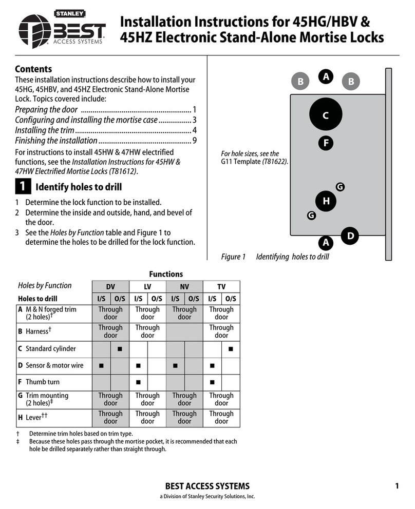
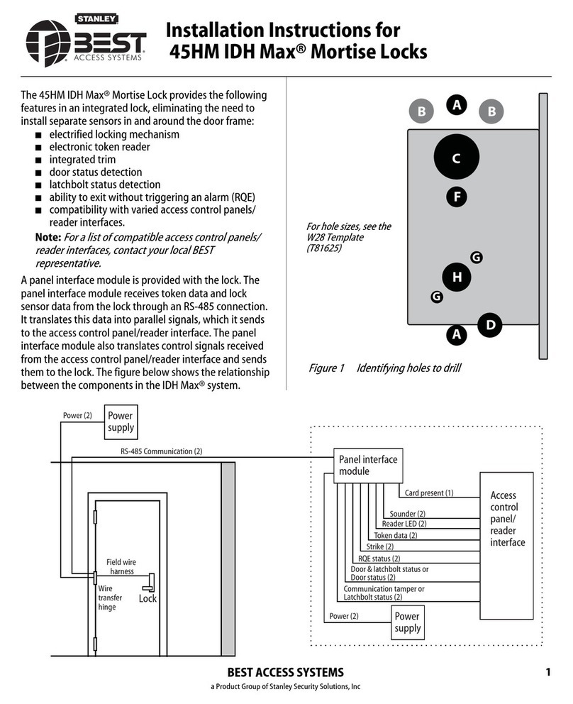
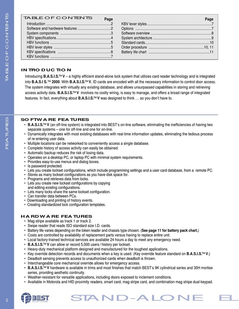
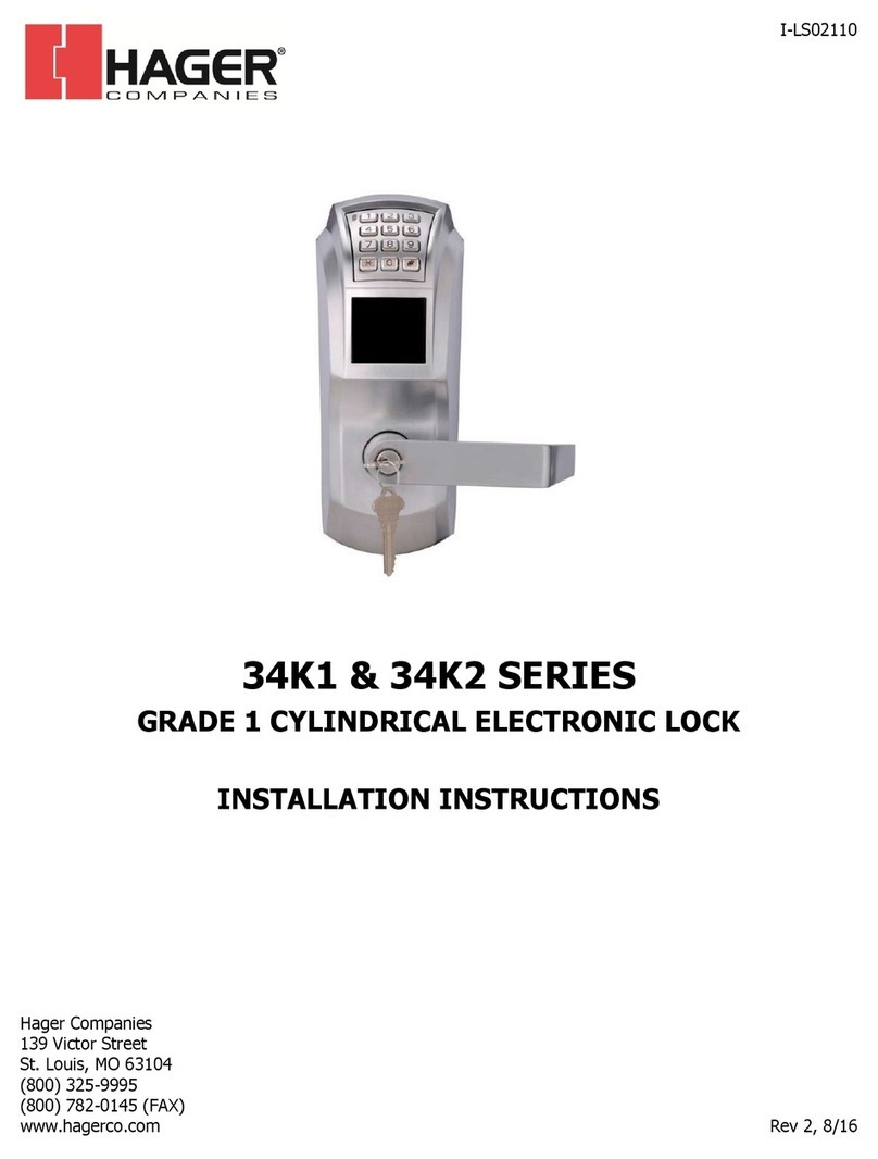
BEST ACCESS SYSTEMS B.A.S.I.S. V User manual

SERVICE MANUAL
SERVICE MANUAL

CREDITS/COPYRIGHT
©2001–2002 Best Lock Corporation dba Best Access Systems. All rights
reserved. Printed in the United States of America.
Information in this document is subject to change without notice and does not
represent a commitment on the part of Best Access Systems. The software described in
this document are furnished under a license agreement or nondisclosure agreement.
This publication is intended to be an accurate description and set of instructions
pertaining to its subject matter. However, as with any publication of this complexity,
errors or omissions are possible. Please call your BEST distributor or Best Access
Systems at (317) 849-2250 if you see any errors or have any questions. No part of this
manual and/or databases may be reproduced or transmitted in any form or by any
means, electronic or mechanical, including photocopying, recording, or information
storage and retrieval systems, for any purpose, without the express written permission
of Best Access Systems.
This document is distributed as is, without warranty of any kind, either express or
implied, respecting the contents of this book, including but not limited to implied
warranties for the publication’s quality, performance, merchantability, or fitness for any
particular purpose. Neither Best Access Systems, nor its dealers or distributors shall be
liable to the user or any other person or entity with respect to any liability, loss, or
damage caused or alleged to be caused directly or indirectly by this publication.
The Best Access Systems logo and B.A.S.I.S. are registered trademarks of Best Lock
Corporation.
The Life Safety Code is a registered trademark of the National Fire Protection
Association.
Von Duprin is a registered trademark of Von Duprin, Inc.
Lubriplate is a registered trademark of Fiske Brothers Refining Company.
Written and designed by Best Access Systems and Avalon Group, Inc., Indianapolis,
Indiana.
T61805 Rev A 1838789 ER-7991-6 July 2002

B.A.S.I.S. V Service Manual iii
CONTENTS
FIGURES IX
GETTING STARTED 1–1
Introduction 1–1
B.A.S.I.S. V product overview 1–2
System overview 1–2
Mortise lock overview 1–4
Cylindrical lock overview 1–4
Certifications and standards 1–5
B.A.S.I.S. V Locks 1–5
Mortise locks 1–5
Cylindrical locks 1–5
Exit hardware trim 1–5
Documentation package 1–6
Technical support 1–8
Support services 1–8
Telephone technical support 1–8
STANDARD FUNCTIONS AND PARTS 2–1
Function descriptions 2–2
Mortise functions 2–2
Cylindrical function 2–4
Trim components 2–5
Magnetic stripe reader and trim 2–5
Smart card reader and trim 2–8
Dual validation reader and trim 2–11
Proximity reader and trim 2–14

Contents
iv B.A.S.I.S. V Service Manual
Mortise components 2–17
Mortise case 2–17
Other mortise components 2–19
Cylindrical components 2–21
Cylindrical chassis 2–22
Other cylindrical lock components 2–23
EXIT HARDWARE TRIM FUNCTIONS AND PARTS 3–1
Function descriptions 3–2
Trim components 3–3
Magnetic stripe reader and trim 3–3
Smart card reader and trim 3–6
Dual validation reader and trim 3–9
Proximity reader and trim 3–12
Cylinders and related components 3–15
Mortise cylinder and related components 3–15
Rim cylinder and related components 3–16
Levers 3–17
SHARED STANDARD AND EXIT HARDWARE TRIM PARTS 4–1
Reader conversion 4–2
Converting to a magnetic stripe reader 4–2
Converting to a smart card reader 4–2
Converting to a dual validation reader 4–2
Converting to an HID or a Motorola proximity reader 4–2
Tasks to perform for converting 4–2
Field replacement kits 4–4
Reader kits 4–4
Control electronics kits 4–5
Battery kits 4–5
Lens cover kit 4–6
Cable and harness kits for standard B.A.S.I.S. Locks 4–6
Screw kits 4–7
Shared internal screw kits 4–7
Upper escutcheon screw kits for all standard B.A.S.I.S. Locks 4–7
Lower escutcheon screw kits for standard B.A.S.I.S. Locks with brass
escutcheons 4–8
Lower escutcheon screw kits for standard B.A.S.I.S. Locks with zinc
escutcheons 4–8
Battery door screw kits for standard B.A.S.I.S. Locks 4–9
Screw and spring kits for EX Series Exit Hardware Trim 4–9
Internal part kits for EX Series Exit Hardware Trim 4–10
Sensor module kits for standard B.A.S.I.S. Locks 4–10
Other system components 4–11

Contents
B.A.S.I.S. V Service Manual v
SERVICING STANDARD MORTISE TRIM PARTS 5–1
Servicing the levers 5–2
Removing the levers 5–2
Reinstalling the levers 5–2
Servicing the inside and outside escutcheons 5–3
Removing the inside and outside escutcheons 5–3
Reinstalling the inside and outside escutcheons 5–6
Servicing the mounting plates 5–13
Removing the mounting plates 5–13
Reinstalling the mounting plates 5–13
Servicing the core 5–14
Removing the core 5–14
Reinstalling the core 5–14
Servicing the mortise case faceplate 5–15
Removing the mortise case faceplate 5–15
Reinstalling the mortise case faceplate 5–15
Servicing the cylinder 5–16
Removing the cylinder 5–16
Reinstalling the cylinder 5–16
SERVICING STANDARD MORTISE CASE PARTS 6–1
Servicing the mortise case 6–2
Removing and opening the mortise case 6–2
Closing and reinstalling the mortise case 6–2
Changing the hand and bevel 6–3
Changing hand and bevel quick reference 6–3
Changing the hand only 6–5
Changing the bevel only 6–5
Changing the hand and bevel 6–5
Tasks for changing the hand and bevel 6–6
Turning over the hubs 6–6
Turning over the cylinder clamp plate 6–7
Turning over the auxiliary bolt 6–8
Turning over the latchbolt 6–9
Function conversion 6–10
Removing key override 6–10
Adding key override 6–11
Adding a deadbolt 6–12
Removing a deadbolt 6–12
Servicing parts in the mortise case 6–14
Servicing the motor module 6–14
Removing the motor module 6–14
Reinstalling the motor module 6–15

Contents
vi B.A.S.I.S. V Service Manual
Servicing the sensor module 6–16
Removing the sensor module 6–16
Reinstalling the sensor module 6–16
Servicing the deadbolt, turn knob hub, and spacer 6–17
Removing the deadbolt, turn knob hub, and spacer 6–17
Reinstalling the deadbolt, turn knob hub, and spacer 6–18
Servicing the cylinder clamp plate 6–19
Removing the cylinder clamp plate 6–19
Reinstalling the cylinder clamp plate 6–19
SERVICING CYLINDRICAL PARTS 7–1
Servicing the core and throw member 7–2
Removing the core and throw member 7–2
Reinstalling the core and throw member 7–2
Servicing the levers 7–3
Removing the levers 7–3
Removing the keyed lever 7–3
Removing the plain lever 7–3
Reinstalling the levers 7–4
Servicing the inside and outside escutcheons 7–5
Removing the inside and outside escutcheons 7–5
Reinstalling the inside and outside escutcheons 7–8
Servicing the rose liners 7–15
Removing the rose liners 7–15
Reinstalling the rose liners 7–16
Servicing the cylindrical chassis 7–18
Removing the cylindrical chassis 7–18
Reinstalling the cylindrical chassis 7–18
SERVICING EXIT HARDWARE TRIM PARTS 8–1
Servicing the battery cover 8–2
Removing the battery cover 8–2
Reinstalling the battery cover 8–3
Servicing the battery pack 8–4
Removing the battery pack 8–4
Reinstalling the battery pack 8–5
Servicing the battery bracket 8–6
Removing the battery bracket 8–6
Reinstalling the battery bracket 8–7
Servicing the exit hardware 8–8
Removing the exit hardware 8–8
Reinstalling the exit hardware 8–8
Servicing the core 8–9
Removing the core 8–9
Reinstalling the core 8–9

Contents
B.A.S.I.S. V Service Manual vii
Servicing the cylinder 8–10
Removing the mortise cylinder 8–10
Reinstalling the mortise cylinder 8–10
Removing the rim cylinder for Precision Hardware installations 8–11
Reinstalling the rim cylinder for Precision Hardware installations 8–11
Removing the rim cylinder for Von Duprin installations 8–12
Reinstalling the rim cylinder for Von Duprin installations 8–12
Servicing the B.A.S.I.S. escutcheon 8–13
Removing the escutcheon 8–13
Reinstalling the escutcheon 8–14
SERVICING STANDARD OUTSIDE ESCUTCHEON PARTS 9–1
Servicing the escutcheon gasket 9–2
Removing the escutcheon gasket 9–2
Reinstalling the escutcheon gasket 9–2
Servicing the lens covers 9–3
Removing the lens covers 9–3
Reinstalling the lens covers 9–3
Servicing the harness clamp 9–4
Removing the harness clamp 9–4
Reinstalling the harness clamp 9–4
Servicing the upgrade cable 9–5
Removing the upgrade cable 9–5
Reinstalling the upgrade cable 9–5
Servicing the sensor harness 9–6
Removing the sensor harness 9–6
Reinstalling the sensor harness 9–6
Servicing the primary harness 9–7
Removing the primary harness 9–7
Reinstalling the primary harness 9–8
Servicing the control electronics boards 9–10
Removing the magnetic stripe control electronics board 9–10
Reinstalling the magnetic stripe control electronics board 9–11
Removing the smart card control electronics board 9–12
Reinstalling the smart card control electronics board 9–13
Removing the dual validation control electronics board 9–15
Reinstalling the dual validation control electronics board 9–15
Removing the proximity control electronics board 9–16
Reinstalling the proximity control electronics board 9–17
Servicing the reader assemblies 9–19
Removing the magnetic stripe reader assembly 9–19
Reinstalling the magnetic stripe reader assembly 9–21
Removing the smart card reader assembly 9–22
Reinstalling the smart card reader assembly 9–24

Contents
viii B.A.S.I.S. V Service Manual
Removing the dual validation reader assembly 9–25
Reinstalling the dual validation reader assembly 9–27
Removing the proximity reader assembly 9–28
Reinstalling the proximity reader assembly 9–29
SERVICING EXIT HARDWARE TRIM ESCUTCHEON PARTS 10–1
Servicing the mounting standoffs 10–2
Removing the mounting standoffs 10–2
Reinstalling the mounting standoffs 10–2
Servicing the escutcheon gasket 10–3
Removing the escutcheon gasket 10–3
Reinstalling the escutcheon gasket 10–3
Servicing the lift finger 10–4
Removing the lift finger 10–4
Reinstalling the lift finger 10–5
Servicing the mounting plate 10–6
Removing the mounting plate 10–6
Reinstalling the mounting plate 10–7
Servicing the lever return springs 10–8
Removing the lever return springs 10–8
Reinstalling the lever return springs 10–8
Servicing the lens covers 10–9
Removing the lens covers 10–9
Reinstalling the lens covers 10–9
Servicing the primary harness 10–9
Removing the primary harness 10–10
Reinstalling the primary harness 10–10
Servicing the control electronics boards 10–10
Removing the magnetic stripe control electronics board 10–10
Reinstalling the magnetic stripe control electronics board 10–11
Removing the smart card control electronics board 10–11
Reinstalling the smart card control electronics board 10–11
Removing the dual validation control electronics board 10–11
Reinstalling the dual validation control electronics board 10–12
Removing the proximity control electronics board 10–13
Reinstalling the proximity control electronics board 10–13
Servicing the reader assemblies 10–13
Removing the magnetic stripe reader assembly 10–13
Reinstalling the magnetic stripe reader assembly 10–14
Removing the smart card reader assembly 10–14
Reinstalling the smart card reader assembly 10–14
Removing the dual validation reader assembly 10–14
Reinstalling the dual validation reader assembly 10–15
Removing the proximity reader assembly 10–15
Reinstalling the proximity reader assembly 10–15

Contents
B.A.S.I.S. V Service Manual ix
Servicing the motor assembly 10–16
Removing the motor assembly 10–16
Reinstalling the motor assembly 10–17
Servicing the locking plate 10–20
Removing the locking plate 10–20
Reinstalling the locking plate 10–21
Servicing the yoke 10–22
Removing the yoke 10–22
Reinstalling the yoke 10–23
Servicing the beam and beam roller 10–24
Removing the beam and beam roller 10–24
Reinstalling the beam and beam roller 10–25
Servicing the lever assembly 10–26
Removing the lever assembly 10–26
Reinstalling the lever assembly 10–27
Servicing the shear pin 10–28
Removing the shear pin 10–28
Reinstalling the shear pin 10–29
Changing the handing 10–30
MAINTENANCE 11–1
Replacing the backup battery 11–2
Removing the backup battery 11–2
Reinstalling the backup battery 11–3
Replacing or upgrading the battery pack 11–4
Removing the battery pack for a standard lock 11–4
Reinstalling the battery pack for a standard lock 11–6
Removing the battery pack for exit hardware trim 11–8
Reinstalling the battery pack for exit hardware trim 11–9
Adding key override sensing to Standard B.A.S.I.S. Mortise Locks 11–10
Performing diagnostics using a PDA 11–13
Diagnostics overview 11–13
Viewing diagnostics information 11–14
Changing a lock’s online mode 11–18
Unlocking a door temporarily 11–19
Resetting the use count 11–19
Clearing the diagnostics code 11–20
TROUBLESHOOTING 12–1
Visual and audible response quick reference 12–2
Enabling communications without a card or password 12–3
Opening a standard B.A.S.I.S. Lock with dead batteries 12–6
Responding to problems 12–7

Contents
xB.A.S.I.S. V Service Manual
LOCK HISTORY EVENT TYPES A–1
INSTALLATION INSTRUCTIONS B–1
INDEX C–1

B.A.S.I.S. V Service Manual xi
FIGURES
GETTING STARTED
System overview diagram 1–3
Mortise lock overview diagram 1–4
Cylindrical lock overview diagram 1–4
STANDARD FUNCTIONS AND PARTS
Understanding mortise function drawings 2–2
Understanding the cylindrical function drawing 2–4
Cylindrical chassis diagram 2–21
Other cylindrical lock components 2–23
EXIT HARDWARE TRIM FUNCTIONS AND PARTS
Mortise cylinder and related components diagram 3–15
Rim cylinder and related components diagram 3–16
Levers diagram 3–17
SHARED STANDARD AND EXIT HARDWARE TRIM PARTS
Other system components diagram 4–11
SERVICING STANDARD MORTISE TRIM PARTS
Removing and reinstalling the levers 5–2
Removing the battery door (four-cell door shown) 5–3
Removing the battery pack (four-cell pack shown) 5–4
Removing the inside escutcheon 5–4
Disconnecting the motor connector and sensor connector 5–5
Removing the bushings and trim hole inserts 5–5

Figures
xii B.A.S.I.S. V Service Manual
Locating the backup battery tab 5–6
Reinstalling the trim hole inserts and bushings 5–7
Feeding the wire harness connectors through the harness hole 5–8
Making the motor connection and sensor connections 5–9
Securing the escutcheons 5–10
Reinstalling the battery pack (four-cell pack shown) 5–11
Reinstalling the battery door (four-cell door shown) 5–12
Removing and reinstalling the mounting plates 5–13
Removing and reinstalling the core 5–14
Removing and reinstalling the mortise case faceplate 5–15
Removing and reinstalling the cylinder 5–16
SERVICING STANDARD MORTISE CASE PARTS
Removing and reinstalling the mortise case 6–2
Explanation of the hand and bevel of the door 6–3
Motor module and locking bar in place 6–7
Turning over the auxiliary bolt 6–8
Latchbolt with anti-friction latch lever in position 6–9
Removing and reinstalling the motor module 6–14
Positioning the turn knob hub and deadbolt spring 6–18
Removing and reinstalling the cylinder clamp plate 6–19
SERVICING CYLINDRICAL PARTS
Removing the core and throw member 7–2
Reinstalling the core and throw member 7–2
Removing the keyed lever 7–3
Removing the plain lever 7–3
Reinstalling the levers 7–4
Removing the battery door (four-cell door shown) 7–5
Removing the battery pack (four-cell pack shown) 7–6
Removing the escutcheon 7–6
Disconnecting the motor connector 7–7
Removing the bushings, trim hole inserts, and hub washers 7–7
Locating the backup battery tab 7–8
Reinstalling the bushings, trim hole inserts, and hub washers 7–9
Feeding the wire harness connectors through the harness hole 7–10
Connecting the motor connector 7–11
Securing the escutcheons 7–12
Reinstalling the battery pack (four-cell pack shown) 7–13
Reinstalling the battery door (four-cell door shown) 7–14

Figures
B.A.S.I.S. V Service Manual xiii
Removing the inside rose liner 7–15
Removing the outside rose liner 7–15
Reinstalling the outside rose liner 7–16
Reinstalling the inside rose liner 7–17
SERVICING EXIT HARDWARE TRIM PARTS
Removing and reinstalling the battery cover on the battery bracket 8–2
Removing and reinstalling the battery pack 8–4
Removing and reinstalling the battery bracket on the door 8–6
Removing and reinstalling the com port in the battery bracket 8–6
Removing and reinstalling the core 8–9
Mortise cylinder components 8–10
Rim cylinder components 8–11
Removing and reinstalling the rim cylinder for Precision Hardware installations
8–11
Removing and reinstalling the rim cylinder for Von Duprin installations 8–12
Removing and reinstalling the escutcheon 8–13
SERVICING STANDARD OUTSIDE ESCUTCHEON PARTS
Removing and reinstalling the escutcheon gasket 9–2
Removing and reinstalling the lens covers (smart card reader shown) 9–3
Removing and reinstalling the harness clamp (smart card reader shown) 9–4
Removing and reinstalling the upgrade cable (smart card reader shown) 9–5
Removing and reinstalling the sensor harness (smart card reader shown) 9–6
Removing and reinstalling the primary harness from the electronics board (smart
card reader shown) 9–7
Disconnecting the sounder and com port from the outside escutcheon 9–8
Connecting the sounder and com port to the outside escutcheon 9–9
Removing and reinstalling the magnetic stripe control electronics board 9–10
Removing and reinstalling the smart card control electronics board 9–12
Disconnecting the flex cable from the smart card control electronics board
9–13
Connecting the flex cable to the smart card control electronics board 9–14
Removing and reinstalling the dual validation control electronics board 9–15
Removing and reinstalling the proximity control electronics board 9–17
Removing and reinstalling the screws for the magnetic stripe reader assembly
9–19
Removing the magnetic stripe reader assembly from the outside escutcheon
9–20
Positioning the magnetic stripe reader assembly 9–21
Removing and reinstalling the screws for the smart card reader assembly 9–22

Figures
xiv B.A.S.I.S. V Service Manual
Removing the smart card reader assembly from the outside escutcheon 9–23
Positioning the smart card reader assembly 9–24
Removing and reinstalling the screws for the dual validation reader assembly
9–25
Removing the dual validation reader assembly from the outside escutcheon
9–26
Positioning the dual validation reader assembly 9–27
Removing the proximity reader assembly from the outside escutcheon 9–28
Positioning the proximity reader assembly 9–29
SERVICING EXIT HARDWARE TRIM ESCUTCHEON PARTS
Removing and reinstalling the mounting standoffs 10–2
Removing and reinstalling the escutcheon gasket 10–3
Removing and reinstalling the lift finger (Precision Hardware rim configuration
shown) 10–4
Removing and reinstalling the mounting plate 10–6
Removing and reinstalling the lever return springs 10–8
Removing the motor assembly 10–16
Rotating the motor assembly gear 10–17
Routing the motor harness 10–18
Reinstalling the motor assembly 10–19
Removing and reinstalling the locking plate 10–20
Reinstalling the locking plate 10–21
Removing and reinstalling the yoke 10–22
Removing and reinstalling the c-clip 10–24
Removing and reinstalling the beam and beam roller 10–25
Removing and reinstalling the lever assembly 10–26
Removing and reinstalling the shear pin 10–28
Changing the handing 10–31
MAINTENANCE
Removing the backup battery (escutcheon for standard mortise lock shown)
11–2
Reinstalling the backup battery (escutcheon for standard mortise lock shown)
11–3
Removing the battery door (four-cell door shown) 11–4
Removing the battery pack (four-cell pack shown) 11–5
Reinstalling the battery pack (eight-cell pack shown) 11–6
Reinstalling the battery door (eight-cell door shown) 11–7
Removing and reinstalling the battery cover on the battery bracket 11–8
Removing and reinstalling the battery pack 11–8

Figures
B.A.S.I.S. V Service Manual xv
Connecting the sensor harness to the electronics board 11–10
Removing the V Series sensor switch assembly 11–11
B.A.S.I.S. Transport Diagnostics window and Diagnostics Codes window
11–13
Connecting the PDA to a standard lock 11–15
Locating the communication port for exit hardware trim 11–15
Starting B.A.S.I.S. Transport 11–16
Disconnecting the programming cable from the lock 11–17
TROUBLESHOOTING
Enabling communications with the password override button (escutcheon for
standard mortise lock shown) 12–4
Connecting the programming cable to the lock 12–6

Figures
xvi B.A.S.I.S. V Service Manual

B.A.S.I.S. V Service Manual 1–1
1GETTING STARTED
INTRODUCTION
The B.A.S.I.S. V Service Manual contains essential
information to help you maintain your B.A.S.I.S. V
Locks and EX Series Exit Hardware Trim.
Throughout this manual, the term standard
B.A.S.I.S. V Locks is used to refer to 35HBV Mortise
Locks and 93KBV–95KBV Cylindrical Locks.
The term EX Series Exit Hardware Trim refers to
EXBV Exit Hardware Trim. B.A.S.I.S. EX Series Exit
Hardware Trim is available for use with the following
types of exit devices manufactured by Precision
Hardware (1000 Series and 2000 Series) and Von
Duprin (98/99 Series):
■rim
■mortise
■surface vertical rod
■concealed vertical rod.
Standard B.A.S.I.S. V Locks and EX Series Exit
Hardware Trim are available with the following types
of readers:
■magnetic stripe card readers
■smart card readers
■dual validation (magnetic stripe card/keypad)
readers
■Motorola and HID proximity card readers.

Getting Started
1–2 B.A.S.I.S. V Service Manual
B.A.S.I.S. V PRODUCT OVERVIEW
System
overview
Figure 1.1 shows the components of the B.A.S.I.S. V system. The table
below defines each of the components in the system.
Components Definition
Magnetic stripe card
encoder
Device that reads, encodes, and erases information on a
magnetic stripe card.
Smart card encoder
(not shown)
Device that reads, encodes, and erases information on a smart
card.
Magnetic stripe
electronic lock
A battery-powered, self-contained, programmable lock that
uses standard magnetic stripe cards and controls access to a
door.
Smart card
electronic lock
(not shown)
A battery-powered, self-contained, programmable lock that
uses smart cards and controls access to a door.
Dual validation
electronic lock
(not shown)
A battery-powered, self-contained, programmable lock that
uses standard magnetic stripe cards and PINs, and controls
access to a door.
Proximity card
electronic lock
(not shown)
A battery-powered, self-contained, programmable lock that
uses proximity cards and controls access to a door.
Exit hardware trim
(not shown)
B.A.S.I.S. escutcheon assembly (including B.A.S.I.S. reader and
control electronics) and external battery compartment used
with mortise, rim, concealed vertical rod, and surface vertical
rod exit hardware (panic) devices.
PDA running
B.A.S.I.S. Transport
software
Device that lets you transfer reader configurations from
B.A.S.I.S. 2002 System Administration to the locks, transfer
history records from B.A.S.I.S. Locks and EX Series Exit
Hardware Trim to System Administration, and view
diagnostics information for B.A.S.I.S. Locks and EX Series Exit
Hardware Trim.
B.A.S.I.S. 2002
software
Software that lets you define programming settings and the
user database for groups of locks, as well as individual locks.
The software lets you view and print information about locks
at any time.
Access card A card containing identification information. A card is given to
a user and is similar to a key, letting the user gain access to a
controlled area.
Programming cable A cable for connecting B.A.S.I.S. Locks and Exit Hardware
Trim to the serial cable.
Serial cable A cable for connecting the programming cable to the PDA.

Getting Started
B.A.S.I.S. V Service Manual 1–3
Figure 1.1 System overview diagram
Personal digital assistant
(PDA) running B.A.S.I.S.
Transport software
Personal computer running
B.A.S.I.S. 2002 software
Access card
Magnetic stripe
card encoder
Mortise
magnetic stripe
electronic lock
Programming cable
Serial cable Not shown:
– Cylindrical magnetic stripe
electronic lock
– Mortise and cylindrical smart
card electronic locks
– Mortise and cylindrical
proximity electronic locks
– Mortise and cylindrical dual
validation electronic locks
– Exit hardware trim
– Smart card encoder

Getting Started
1–4 B.A.S.I.S. V Service Manual
Mortise lock
overview
The diagram below shows an exploded view of the components of the
B.A.S.I.S. V Mortise Lock, indicating their orientation to the door.
Cylindrical lock
overview
The diagram below shows an exploded view of the components of the
B.A.S.I.S. V Cylindrical Lock, indicating their orientation to the door.
Figure 1.2 Mortise lock overview diagram
Outside trim
Inside trim
Figure 1.3 Cylindrical lock overview diagram
Outside trim
Inside trim
Other manuals for B.A.S.I.S. V
1
Table of contents
Other BEST ACCESS SYSTEMS Door Lock manuals
BEST ACCESS SYSTEMS
BEST ACCESS SYSTEMS 45HG User manual

BEST ACCESS SYSTEMS
BEST ACCESS SYSTEMS 34HW User manual

BEST ACCESS SYSTEMS
BEST ACCESS SYSTEMS V Series User manual

BEST ACCESS SYSTEMS
BEST ACCESS SYSTEMS 45HM IDH Max 1300 User manual

BEST ACCESS SYSTEMS
BEST ACCESS SYSTEMS 45HM IDH Max Mortise Lock User manual
BEST ACCESS SYSTEMS
BEST ACCESS SYSTEMS 45HM IDH Max Mortise Lock User manual
BEST ACCESS SYSTEMS
BEST ACCESS SYSTEMS W Series User manual
BEST ACCESS SYSTEMS
BEST ACCESS SYSTEMS B.A.S.I.S. V User manual