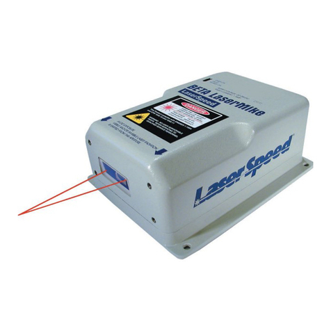
Beta LaserMike BenchMike Pro Installation and operating instructions

BenchMike Pro
ID/OD/WALL
Addendum
NDC Technologies
8001 Technology Blvd.
Dayton,
Ohio 45424
U.S.A.
© 2018 NDC Technologies
Main Phone +1 (937) 233-9935
General Fax +1 (
937) 233-7284
www.betalasermike.com
Making Light Work

Proprietary Notice
The information and design disclosed herein were originated by and are the property of NDC Technologies. NDC
Technologies reserves all patent, proprietary design, manufacturing, reproduction use, and sales rights thereto,
and to any article disclosed therein, except to the extent rights are expressly granted to others. The foregoing
does not apply to vendor proprietary parts.
In-line with NDC’s policy of continuous improvement, the information contained in this document may change to
allow the introduction of design improvements.
BenchMike Pro ID/OD/WALL Addendum
Part Number: MAN/EN5008-0098
Revision: C
Date of Release: September, 2018

Contact NDC
Online Support
You can access the NDC Customer Support portal, myNDC at https://ndc.custhelp.com.
myNDC is a cloud-based portal that allows you to get product support by phone, ask a question, provide feed-
back, submit an RMA request or access information in our on-line knowledge database. You can browse the
myNDC site or create a myNDC account.
x To create a myNDC account, click the Log in or Sign up button. After creating the account, you will be
immediately logged in. To log in on subsequent visits to myNDC, click the Log in or Sign up button, en-
ter your user name and password, and then click Log in.
x To submit an RMA, click on the RMA Request tab and follow the on-screen instructions.

NDC Contact Numbers
Please have your sales order number at hand before contacting NDC.
− Beta LaserMike Gauges
Beta LaserMike Gauges
Americas
+1 937 233 9935
Asia Pacific
India: +91-124-2789507
Alternative number +91
-124-
2789508
Japan: +81 (0)3 3255 8157
All other countries: +1 937 233 9935
Alternative number +44 1621 852244
China +86 21 61133609
EMEA
(Europe,
Middle East,
Africa)
Germany: 0800 1123194
France: 0810 600 400
Italy: +39 0331 454 207
All other countries (English speaking):
+44 1621 852244
Please select option 3 to be
connected to the service team

BenchMike Pro ID/OD/WALL Addendum: Caution i
Caution
x This equipment must be earthed/grounded.
x Under NO circumstances should the earth safety
connections be broken – internal damage to sensi-
tive electronic components may occur and at worst
electrocution to personnel may result.
x Digital outputs are open - collector outputs, with max-
imum specs of 35 V DC and 250ma. These levels
must not be exceeded.
x Maintenance, repairs and electrical connections
should be performed by a suitably qualified person
for the country of installation.
x The equipment contains a slow blow type fuse to
protect against input power overloads and is not user
replaceable.
Intended Use
If the equipment is used in a manner not specified by the
manufacturer, the protection provided by the equipment may
be impaired.
Laser Safety Precautions
The BenchMike Pro uses a Collimated Diode laser which emits red light at a wavelength of 635nm. No invisible or
otherwise harmful radiation is emitted.
The radiant output power of either internal laser (whether it be a laser diode or gas laser) and of the entire
BenchMike Pro is relatively low. The laser beam will not harm your skin, and your eyes are protected by a natural
aversion response that will cause you to blink or look away. However, the laser light emitted from the BenchMike
Pro should be treated with caution and common sense. Do not attempt to look into the BenchMike Pro, and avoid
staring at reflections of the beam.
The American National Standard for the Safe Use of Lasers (ANSI Z136.1 — 2014) classifies this laser product
as Low Power — Class II and provides reasonable and adequate guides for its safe use. The user of the Bench-
Mike Pro and other personnel responsible for its safe use should consult this ANSI standard. It is available from:
American National Standards Institute
1430 Broadway
New York, New York 10018
The Center for Devices and Radiological Health (CDRH) of the Food and Drug Administration has established
regulations for manufacturers of laser products. All laser products sold in the U.S.A. since August, 1976 must be
certified by the manufacturer as meeting certain product performance (safety) standards, and each laser must
bear a label indicating compliance with the standard and denoting laser hazard classification.

ii BenchMike Pro ID/OD/WALL Addendum: Caution
Labels and Safety Features
This section acquaints you with the advisory and identification labels on the instrument and the safety features
incorporated into the design of the instrument. The following figures show the identification and advisory labels on
the BenchMike Pro.
Front View
Model 2025
DB-9 FEMALE
SERIAL 1
LASER SAFETY LABEL
SERIAL TAG
ETHERNET
DB-25 MALE I/O
BNC
DB-25 FEMALE FIXTURE
USB-A PRINTER
USB-B SERIAL
Aperture
label
Scanning
laser beam
Laser safety label
(back panel)
Laser emission
LED

BenchMike Pro ID/OD/WALL Addendum: Caution iii
Model 2050
FCC Manual Digital Devices Statement
NOTE: This equipment has been tested and found to comply with the limits for a Class A digital device, pursuant
to part 15 of the FCC Rules. These limits are designed to provide reasonable protection against harmful interfer-
ence when the equipment is operated in a commercial environment. This equipment generates, uses, and can
radiate radio frequency energy and, if not installed and used in accordance with the instruction manual, may
cause harmful interference to radio communications. Operation of the equipment in a residential area is likely to
cause harmful interference, in which case, the user will be required to correct the interference at his own expense.
Important Note
This BenchMike Pro ID/OD/WALL Addendum is designed to be used in conjunction with the BenchMike
Pro Instruction Handbook and BenchMike Pro Operator Guide. This Addendum contains only specific in-
formation about the BenchMike Pro ID/OD/WALL, while the Instruction Handbook and Operator Guide
contain information about all BenchMike Pros, with and without special fixtures.
Your questions about the use of the ID/OD/WALL features of the BenchMike Pro should be answered by
this Addendum, while your more general questions about the use of the BenchMike Pro should be an-
swered by the Instruction Handbook and Operator Guide.
DB-9 FEMALE
SERIAL 1
USB-A PRINTER
LASER SAFETY LABEL
SERIAL TAG
ETHERNET
USB-B SERIAL
DB-25 MALE I/O
BNC
DB-25 FEMALE FIXTURE

iv BenchMike Pro ID/OD/WALL Addendum: Table of Contents
Table of Contents
1 QUICK START .................................................................................................................................... 1-1
1.1 INTRODUCTION ........................................................................................................................... 1-1
1.2 QUICK START PROCEDURE ......................................................................................................... 1-1
1.3 INSTALLATION ............................................................................................................................ 1-2
1.4 OPERATION ............................................................................................................................... 1-3
1.4.1 Mastering for ID/OD/WALL Measurements..................................................................... 1-3
1.4.2 Taking Measurements ..................................................................................................... 1-3
1.4.3 Mastering for ID/OD/WALL with Force Gauge measurements ....................................... 1-4
1.5 FACTORY DEFAULTS .................................................................................................................. 1-5
1.5.1 Changing the Fixture Default Settings............................................................................. 1-5
1.5.2 Changing Main Screen Defaults...................................................................................... 1-7
1.5.3 Default Settings ............................................................................................................... 1-9
2 INTRODUCTION ................................................................................................................................. 2-1
2.1 BENCHMIKE OPTIONS ................................................................................................................ 2-1
2.1.1 Interfaces ......................................................................................................................... 2-1
2.1.2 Measurement Fixtures..................................................................................................... 2-1
2.2 USING THE BENCHMIKE .............................................................................................................. 2-2
2.3 MEASURING A PRODUCT ............................................................................................................ 2-2
2.4 UNDERSTANDING THE DATA DISPLAY .......................................................................................... 2-3
2.4.1 What are Libraries? ......................................................................................................... 2-4
2.4.2 What are Features?......................................................................................................... 2-4
2.4.3 ID, OD, and WALL Features............................................................................................ 2-4
3 WORKHOLDING FIXTURES ............................................................................................................. 3-1
3.1 ID/OD/WALL FIXTURES ............................................................................................................ 3-1
3.1.1 Terminology ..................................................................................................................... 3-1
3.1.2 How the ID/OD/WALL Fixture Measures......................................................................... 3-2
3.1.3 Installing the Fixture ........................................................................................................ 3-3
3.1.4 Taking Measurements ..................................................................................................... 3-3
3.2 DESCRIPTION OF FIXTURES ........................................................................................................ 3-4
3.2.1 Auto-Rotating ID/OD/WALL Fixture for Small Tube & Hose ........................................... 3-4
3.2.2 Auto-Rotating ID/OD/WALL Fixture with Force Gauge for Very Small Tube & Hose ..... 3-6
3.2.3 Auto-Rotating Heavy Duty ID/OD/WALL Fixture for Large Tube & Hose ....................... 3-8
3.2.4 Manual ID/OD/WALL Fixture for Small Tube & Hose ................................................... 3-10

BenchMike Pro ID/OD/WALL Addendum: Table of Contents v
3.3 OTHER FIXTURES ..................................................................................................................... 3-11
4 SETUP ................................................................................................................................................ 4-1
4.1 FEATURE ICON ........................................................................................................................... 4-1
4.2 SYSTEM FUNCTIONS .................................................................................................................. 4-2
4.3 SETTINGS FUNCTIONS ................................................................................................................ 4-2
4.3.1 Batch Report.................................................................................................................... 4-2
4.3.2 Fixture Sample Report..................................................................................................... 4-3
4.3.3 Fixture Batch Report........................................................................................................ 4-4
4.4 MEASUREMENT FUNCTIONS ........................................................................................................ 4-5
5 ADVANCED CAPABILITIES .............................................................................................................. 5-1
5.1 ADVANCED SCREEN CAPABILITIES .............................................................................................. 5-1
6 SERVICING YOUR EQUIPMENT ...................................................................................................... 6-1


CHAPTER
1
BenchMike Pro ID/OD/WALL Addendum: Quick Start 1-1
1 Quick Start
1.1 Introduction
This manual contains information about the operation of the NDC Technologies BenchMike Pro Benchtop Laser
Micrometers with the ID/OD/WALL option. This includes the following two models:
x BenchMike Pro Model 2025
x BenchMike Pro Model 2050
1.2 Quick Start Procedure
This Quick Start is designed to help those who are somewhat familiar with the operation of benchtop laser mi-
crometers during installation, setup, and initial operation.
Model 2025 BenchMike Pro
Touchscreen
display
Aperture
label
Scanning
laser beam
Laser safety label
(back panel)
Connectors
(not shown)
Measurement
area

1-2 BenchMike Pro ID/OD/WALL Addendum: Quick Start
Note: Your BenchMike Pro is configured at the factory for the following parameters:
• Transparent product measurement
• Automatic rotation of product for 360° with Intelligent Fixture, taking measurements every 90° (4 position meas-
urement)
• ID/OD/WALL measurement
• Home fixture at end of measurement cycle
To alter these settings, see the detailed descriptions of each setup page in Setup.
Note: You can scroll through the data items that have been created in the default setup by touching the scroll ar-
row on the right side of the screen.
Note that this Supplemental Manual contains information about the BenchMike Pro ID/OD/WALL only. For more
general information about all BenchMike Pro models, consult the BenchMike Pro Instruction Handbook or Opera-
tor Guide.
1.3 Installation
Please follow these steps when unpacking, installing, and operating your BenchMike.
1. Inspect the exterior of the shipping container for damage. If the container is damaged, do not open it.
Contact the carrier and NDC Technologies immediately.
2. If the shipping container is intact, remove and read the packing list.
3. Carefully open the container, remove the shipping spacers, and unpack the BenchMike.
4. Inspect the BenchMike for damage. If damage is suspected, contact the carrier immediately.
5. Check the packing list to ensure that all items have been received.
6. If all items appear undamaged, install the BenchMike by placing it on a horizontal surface in a location
free of excessive physical vibration and where it will not accumulate any amount of dust, dirt, or mist.
7. Check the serial tag on the BenchMike for the correct line voltage. Using the supplied power cord, plug
the BenchMike into the appropriate power source.
8. Mount the desired ID/OD/WALL Fixture in the measurement area, and leave the mounting screws loose
enough for the fixture to move. These will be tightened in Step 10. Plug the fixture’s connector into the
rear panel connector marked FIXTURE (if an In-
telligent Fixture is used). Do not screw the Fix-
ture in place in the BenchMike’s measurement
area yet. Ensure that the correct mandrel is in-
stalled in fixture. The mandrel must be smaller
than the product to be measured. Place the
product to be measured in the measurement
area on the mandrel.
9. Turn the power on via the switch on the rear of
the BenchMike. Within two minutes, the touch
screen will display as shown.
10. Place your index finger or other similar object
next to the pulleys on the right side of the ID/OD/WALL Fixture. Ensure that the laser beam passes mid-

BenchMike Pro ID/OD/WALL Addendum: Quick Start 1-3
way between the pulleys. Make sure that the Fixture is mounted square by pushing on the right side of
the Fixture’s mounting base to take up the clearance in the mounting holes. Tighten the mounting screws,
and ensure that the beam still passes midway between the pulleys on both sides.
11. Touch the Mode icon in the upper left hand corner of the screen, then touch Fixture, and then select
Master ID/OD/WALL if you are performing ID/OD/WALL measurements. Follow on-screen instructions.
12. Touch the Go button to begin taking measurements. The Mode icon will change from red to green, indi-
cating that measurements are being taken and processed, and values will appear on the touch screen.
1.4 Operation
1.4.1 Mastering for ID/OD/WALL Measurements
When a mandrel or fixture is changed, removed, or installed, or if the
BenchMike’s power has been turned off, the fixture must be mastered. In the
mastering process, the dimension A (distance between the top of the man-
drel and the fixture’s upper reference edge) is measured and stored so that
the ID and WALL dimensions can be calculated.
To perform ID, OD, and WALL measurements, you must first perform this
fixture mastering process.
1. Check to ensure that the mandrel is fitted properly in
the fixture and is clean.
2. Remove any part from the mandrel.
3. To master the fixture, select the Mode icon, then
Fixture, and then
Master ID/OD/WALL. While the master gap is being
measured, the Mode icon will be green. When it has
been measured, you may follow the next procedure:
setting up the BenchMike for ID/OD/WALL meas-
urements.
1.4.2 Taking Measurements
Once the fixture has been installed and mastered, measurements can be taken using factory default settings.
Place the product on the mandrel, and touch the Go button. The Mode icon in the upper left hand corner will turn
from a red circle to a green circle. The belts will rotate the product, and measurements will be taken at each loca-
tion.
You can view OD, ID, or WALL measurements by touching the Feature icon in the upper right hand cor-
ner of the screen, and selecting the desired feature from the drop down list.
Mandrel

1-4 BenchMike Pro ID/OD/WALL Addendum: Quick Start
1.4.3 Mastering for ID/OD/WALL with Force
Gauge measurements
When a mandrel or fixture is changed, removed, or installed, or if the
BenchMike’s power has been turned off, the fixture must be mastered. In the
mastering process, the dimension A (distance between the top of the man-
drel and the fixture’s upper reference edge) is measured and stored so that
the ID and WALL dimensions can be calculated.
To perform ID, OD, and WALL measurements, you must first perform this fixture mastering process.
1. Select a mandrel that is close in size to the ID of the sample to be measured. Make sure the sample can
rotate freely on the mandrel.
2. Ensure that the mandrel is fitted properly in the fix-
ture and is clean.
3. Put a straight sample piece on the mandrel.
4. Lower the drive belts onto the sample.
5. Adjust the downward force on the same as low as
possible to provide a reliable rotation of the sample
on the mandrel.
6. Zero the force gauge.
7. Remove the sample from the mandrel.
8. Lower the drive belts onto the mandrel with the top
screw to get the force gauge to read zero.
9. Master the gap.
1.4.3.1 Taking Measurements
1. Place the product on the mandrel.
2. Lower the drive belts onto the product.
3. Adjust the screw at the top of the fixture to read near zero.
4. Touch the GO button. The Mode icon in the upper left hand corner will turn from a
red circle to a green circle. The belts will rotate the product, and measurements
will be taken.
Mandrel

BenchMike Pro ID/OD/WALL Addendum: Quick Start 1-5
1.5 Factory Defaults
1.5.1 Changing the Fixture Default Settings
If you are using an Automatic ID/OD/WALL Fixture and you wish to change the factory default fixture settings,
follow these steps.
1. Select Setup from the lower left corner of the screen,
then System, and then Fixture. Select the desired
Fixture.
2. Select Setup, then Measurement, then Fixtures,
then Fixture 1. If Fixture 1 cannot be selected, se-
lect Control and then enable the ID/OD/Wall fixture
on the Control page.
3. From the Mode tab, ensure the following items are
set correctly.
Select one of the following options for measurement
mode:
Auto
For automatic rotating fixtures: Measurement is initi-
ated by the Go command. At the end of each aver-
aging period (defined in Measurement Setup), the
fixture rotates to the next position and takes meas-
urement data. The number of measurements may be from 2 to 360 and can be entered as a number of
positions or as the angular increment between positions. Measurements are not taken
during rotation.
Manual
For manual and automatic rotating fixtures: Measurement is initiated by the Go command. At the end of
each averaging period (defined in Measurement Setup), the user is prompted to rotate the sample to the
next position and press Go to take the next measurement. Graphical displays are not available in this
mode because the position is not known reliably unless the fixture has a position encoder.
Continuous
For automatic rotating fixtures: Measurement is initiated by the Go command. Measurements are cap-
tured while the fixture is rotating. This mode can be used to capture the Maximum, Minimum, or Maxi-
mum-Minimum (Diff). The user enters the speed and amount of rotation. Graphical displays are not avail-
able in this mode.

1-6 BenchMike Pro ID/OD/WALL Addendum: Quick Start
4. From the Position tab, you can define either the
number of positions (from 2 to 360) or number of
degrees of rotation (from 1 to 360). You can also
select total degrees of rotation values of: 360,
180, or a custom value.
5. From the Motion tab, select the desired values
for the following.
Motion Speed
Sample rotation speed
Enable Half-Stepping
Permits smoother sample rotation
Home Fixture and End of Measurement Cy-
cle
Returns fixture to starting position at end of cy-
cle
Disable Motor After Movement
Turns off fixture’s motor at end of cycle
6. From the ID/OD/WALL tab, determine whether
you wish the Opposite Wall Calculation to be en-
abled or disabled.
When enabled, ID measurements are calculated
by subtracting the two opposite wall sizes from
the diameter. In this mode an even number of
measurement positions must be entered. This
mode is not operable in Manual or Continuous
Modes.
When disabled (not checked), ID measurements
are calculated by subtracting two times the wall
thickness value from the diameter.

BenchMike Pro ID/OD/WALL Addendum: Quick Start 1-7
1.5.2 Changing Main Screen Defaults
When you start your BenchMike for the first time, the data page will appear as previously shown. You can change
the displayed items to suit your requirements. However, see the section on Advanced Screen Capabilities before
changing the ID pages. You can change the OD and WALL data pages as described below because Advanced
Screen Capabilities are not required in their default settings.
1. Touch the Setup button.
2. Touch the Data button.
3. Add or delete any of the following items by changing the Display setting.
The items in the following table can all be displayed on the main page shown above; that is, all the following data
items are sent out via the Serial/Ethernet port. Only these items can be displayed on this page.
Note that you can use the Advanced Screen Option to display items from other features on the main page. Oth-
erwise, only items from the currently loaded feature will be shown on the main page.

1-8 BenchMike Pro ID/OD/WALL Addendum: Quick Start
Fixture Position
Fixture 1 Position
Fixture 2 Position
Nom/Lim/Tol
Deviation
Nominal
Limits
+Reject
+Warning
-Warning
-Reject
Tolerances
+Reject
+Warning
-Warning
-Reject
Part CCount
Position
Size
Size Offset
SQC
Average
Count
Diff/TIR
Maximum
Minimum
Std Dev
Environmental Comp
Optical Plate Temp
CPU Temperature
Part Temp.
Actual Pressure
Barometric Temp.

BenchMike Pro ID/OD/WALL Addendum: Quick Start 1-9
However, the ID/OD/WALL BenchMike has ad-
vanced display capabilities which allow you to display
up to 32 data items per Feature. The boxes with
numbers inside (shown as 2 for AVG OD) indicate
the feature that this data is from. Feature1 is ID, 2 is
OD and 3 contains WalI data. If you wish to make
use of the capabilities shown to the right, see the
Advanced Capabilities section.
1.5.3 Default Settings
The following settings are the factory defaults for your ID/OD/WALL BenchMike.
Measurement\\Measurement Type
Measurement Type 53 (Transparent)
Settings\\SQC Batch
Batch Count = 0
Data
\SIZE\SQC\Average (Avg ID)
Feat 2 Data
\SQC\Average\ (Avg OD)
Feat 3 Data\\SQC\\Average (Avg WALL)
Send Serial Data & Limit Checking Enabled
Send Serial Data & Limit Checking Enabled
Send Serial Data & Limit Checking Enabled
Measurement\\Fixtures\\Control
Collect Data From ID OD Wall Fixture
Measurement
\Fixtures\Fixture 1
Mode Tab
Auto selected
Measurement
\Fixtures\Fixture 1
Position Tab
Number of Positions = 4, Total Degrees of
Rotation = 360
Measurement
\Fixtures\Fixture 1
Motion Tab
Motion Speed = 5 RPM, Half Stepping = En-
abled (checked), Home Fixture = Disabled
(unchecked), Disable Motor = Enabled
(checked)
Measurement
\Fixtures\Fixture 1
ID/OD/Wall Tab
Opposite wall ID calculation = Disabled (un-
checked)
Advanced Screen Capabilities
Disabled to prevent accidental changes to
displays Scroll on Warning or Reject
ID Feature Page Items
AVG ID
AVG OD
AVG WALL
DIF ID

1-10 BenchMike Pro ID/OD/WALL Addendum: Quick Start
OD Feature Page Items
WALL Feature Page Items
DIF OD
DIF WALL
MAX ID
MIN ID
MAX OD
MAX WALL
MIN WALL
PARTS
AVG OD
DIF OD
MAX OD
MIN OD
AVG WALL
DIF WALL
MAX WALL
MIN WALL
Table of contents
Other Beta LaserMike Measuring Instrument manuals
Popular Measuring Instrument manuals by other brands
Challenger Optics
Challenger Optics CO-OLS-MPO12 operating manual

Aquametro
Aquametro AMTRON SONIC D Mounting and operating instructions
Avtech
Avtech room alert 32e/w user guide
Aqualytic
Aqualytic AL100 instruction manual
Check-line
Check-line WT-100 operating instructions
Dilog
Dilog DL7040 instruction manual
