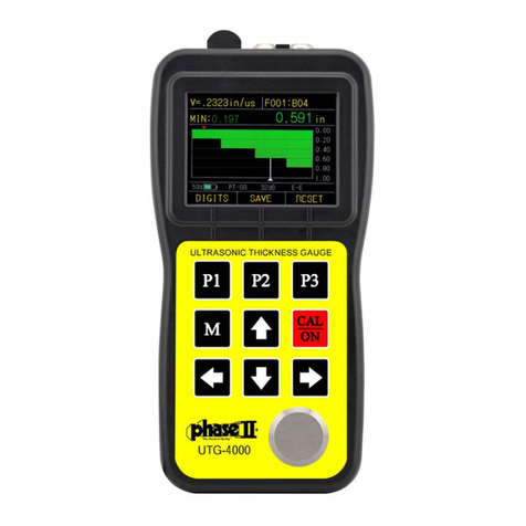
phase II+ UTG-4000 User manual

ModelNo.UTG‐4000
www.phase2plus.com
283 Veterans Blvd
Carlstadt, NJ. 07072
(201) 933-6300
www.phase2plus.com
21IndustrialAveUpperSaddleRiver,NJ.07458
P(201)962‐7373 F(201)962‐8353
E‐mail:info@phase2plus.com

CONTENT
1. GENERAL INTRODUCTION3
1.1 CONSTRUCTION OF THE GAGE........3
1.2 STANDARD CONFIGURATIONS.........3
1.3 OPTIONAL CONFIGURATIONS..........3
1.4 SPECIFICATIONS.............................4
1.5 MAIN FUCTIONS..............................5
2. KEYBOARD FUCTIONS5
3. MEASURING THE THICKNESS6
3.1 PRESET THE MATERIAL’S VELOCITY6
3.2 PRESET OTHER SPECIFICATIONS....7
3.3 CALIBRATION.................................8
3.4 DISPLAY MODES.............................9
3.5 ADJUSTING THE SPECIFICATIONS IN A-SCAN MODE
........................................................11
3.6 REAL CASES ANALYSIS................12
4.CARE AND MAINTENANCES16
4.1 POWER SOURCE INSPECTION......17
4.2.......................................Maintenance
4.3 Service / Support..........................17
APPENDIX: SOUND VELOCITIES OF COMMON MATERIALS17

1. GENERAL INTRODUCTION
UtilizingliveA‐scanandtimebasedB‐scanforabsolutecorrectness,thisnewstateoftheart
thicknessgaugeispackedwithusefulfeaturesallowinguserstobeconfidentofthedisplayedvalueson
themostcriticalofapplications.Thismulti‐functionalunitofferseverythingfrombasicmeasurement,
ScanwithMin/Maxviewing,GO/NOGOdisplayandAdjustableSoundVelocity.Thisdynamicsonicgauge
isde s i g n e d tomeasurethethicknessofmetallicandnon‐metallicmaterialsincriticalsituationsthat
ordinarythicknessgaugescouldn’tdo.
TheUTG‐4000willaccuratelydisplayreadingsineitherinchormillimeterafterasimplecalibrationto
aknownthicknessorsoundvelocity.
1.1CONSTRUCTIONOFTHEGAGE
1.2STANDARDCONFIGURATION
Qty
ThicknessGauge 1
5MHzPROBE 1
AABatteries 2
2ozCouplantGel 1
RuggedCarrycase 1
OperationManual 1
1.3OPTIONALACCESSORIES
High‐temperatureprobe Castironprobe
SmallProbe(6mm) MiniProbe(4mm)
Probecable 5‐Stepblock
DISCLAIMER:
TheUTG‐4000isamulit‐functionalthicknessgaugethatallowstheusertremendouscontroloverthefunctionalityandperformance
ofthisinstrument.Althoughthis providestheuser withcontrolandversatilityfornumerousapplications,italsorequiresthatthe
userbefamiliarwiththefunction,operationandwaveforminterpretationoftheinstrumentaswell.
Itisrecommendedthattheuserspendasufficientamountoftimeworkingwiththisinstrumentpriortofielduse.
Responsibilityforproperuserestssolelywiththeuseofthisinstrument.

1.4SPECIFICATIONS
OperatingPrincipleUltrasonic pulse/echo method with dual
elementprobe
Displaytype2.4”ColorScreen
Resolution0.001”,.01”/0.01mm(Inch/Metricselectable)
MeasuringRange0.02‐20.0” Dependantuponprobe&material
Repeatability+/‐.001” (+/‐0.05mm)
Soundvelocityrange0.0197‐0.3937in/us (500‐9999m/s)
MeasuringError:0.001”(upto0.984”)
0.007”(upto3.03”
0.019”(4”andabove)
DisplayModes:DigitalThicknessReadout
A‐scanorB‐scan
Min/MaxCapture
Diff‐Value/Reduction
V‐PathCorrectionAutomatic
UpdateRateSelectable:4Hz,8Hz,16Hz
Refreshrate4/second
AlarmSettingsMin/MaxAlarm
Dynamicwaveformcolorchangeonalarm
Operatingtemperature14‐122ºF (‐10ºC‐+50ºC)
AutoShut‐OffAfter5minutes
Powersupply3vAAalkalinebatteries(2pc)
OperatingTimeApprox.36hours
Dimensions6.02”x2.99”x1.45” (153x76x37mm)
Weight9.9oz (280g)

1.5MAINFUCTIONS
1.User‐friendlyinterface
2.OptionalA‐scanwaveformdisplay
3.TimebasedB‐scanfunctiondisplayscrosssectionoftestpiece
4.Differentcouplingstatusshowingindifferentcolors
5.Thicknessalarm:automaticalarmwhentheresultexceedsthepresetthicknessrange
6.Limitsvaluemode:Displaystheminimumandmaximumvalueswhenmeasuring
7.Differencemode:gettingthedifferencebetweentheactualvalueandthenormalvalueaswellasthe
percentage
8.Inch/MetricConversion
9.Extralargememory:upto100,000values&1000waveforms
10.SelectableResolution:0.001”,0.01”or.01mm
11.Optionalrectificationmode:RF,fullwave,half+,half‐
12.Optionalwaveform:outlinemodeorfilledmode
13.Approx.batteryLife:35hours
2.KEYBOARDFUCTIONS
Totally,thereare9keysonthekeyboard,including3virtualfunctionkeys(),fourdirection
keys(),twospecializedfunctionkeys().Seethefollowing
illustration(2.1)
2.1KEYBOARDFUCTIONILLUSTRATION

3.MEASURINGTHICKNESS
3.1SoundVelocityCalibration
In order for the gauge to make accurate measurements, it must besettothecorrectsoundvelocityforthe
materialbeingmeasured.Differenttypesofmaterialhavedifferentinherentsoundvelocities.Ifthegaugeisnotsetto
thecorrectsoundvelocity,allofthemeasurementsthegaugemakeswillbeerroneousbysomefixedpercentage.The
One‐Pointcalibrationisthesimplestandmostcommonlyusedcalibrationprocedureoptimizinglinearityoverlarge
ranges. The Two‐pointcalibration allows for greater accuracy over small ranges by calculating the probe zero and
velocity.
Note:OneandTwopointcalibrationsmustbeperformedonmaterialwiththepaintorcoatingremoved.Failureto
removethepaintorcoatingpriortocalibrationwillresultinamultimaterialvelocitycalculationthatmaybedifferent
fromtheactualmaterialvelocityintendedtobemeasured.
Calibrationtoaknownthickness
Note:Thisprocedurerequiresasamplepieceofthespecificmaterialtobemeasured,theexactthicknessof
whichisknown,e.g.fromhavingbeenmeasuredbysomeothermeanssuchasacaliperormicrometer.
1) Performatestonthebuilt‐intestblocktoverifyunitisfunctioningproperly
2) Applycouplanttothesamplepiece.
3) Pressthetransduceragainstthesamplepiece,makingsurethatthetransducersitsflatagainstthesurfaceof
thesample.Thedisplayshouldshowsomethicknessvalue,andthecouplingstatusindicatorshouldappear
steadily.
4) Havingachievedastablereading,removethetransducer.Ifthedisplayedthicknesschangesfromthevalue
shownwhilethetransducerwascoupled,repeatstep3.
(5) Pressthedirectionkeystoadjustthevelocitytomaketheactualthicknessvaluebesamewiththeknown
value.
2.Adjustthevelocitydirectlyifthematerialvelocityisknown.Seeillustration3.1:
3.1VELOCITYADJUSTINGSTEPS

3.2PRESETOTHERSPECIFICATIONS
Press “M”toentertheuserinterface,whichallowsyoutoselectandadjust options like VIEW
MODE, PROBE SETUP, MINIMUM ALARM, MAXIMUM ALARM, NORMAL THICKNESS, MINIMUM of
B‐SCAN, MAXIMUM of B‐SCAN, RECTIFICATION, RECTIFICATION WAVEFORM, RESOLUTION,
LANGUAGE,UPDATERATES,UNITS,ANDDEFAULTSETUP.Seethefollowingfigure:
3.2MenuSelections
VIEWMODE:normalmode,differencemodeandlimitscanningmode.
PROBESETUP:PT‐10/PT‐08(normalprobe),PT‐06(smallprobe),PT‐04(miniprobe),GT‐12(high‐temperature
probe),andZT‐12(castironprobe).
MINIMUMALARM: set the minimum thickness alarm value. The result will be displayedinrediftheactual
thicknessislessthantheminimumvaluepreset.
MAXIMUMALARM: set the maximum thickness alarm value. The result will be displayedinrediftheactual
thicknessismorethanthemaximumvaluepreset.
NORMALTHICKNESS:setthenormalthickness.Therealconcreteapplicationwillbe introduced in the
DIFFERENCEMODE.
MINIMUMofB‐SCAN:setminimumthicknessforB‐scan
MAXIMUMofB‐SCAN:setmaximumthicknessforB‐scan
RECTIFICATIONMODE: RF, full wave, half ‐, half +. RF describes the complete echo waveform; full wave
indicatesthehalf+echoandtheoverturnedhalf‐echo;half–meansputtingoffthehalf+echoandturnthehalf
–overto+;half+meansputtingoffthehalf–echoandonlyleftthehalf+echo.
RECTIFICATIONWAVEFORM:outlinemodeandfillmode.
RESOLUTION:SelectableResolution:0.001”,0.01”or.01mm
LANGUAGE:theinterfacelanguage:ChineseorEnglish.

UNITS:Selectable:mmorinch.
UPDATERATE:Updatetherateofmeasurementresult.Optional4,8or16Hz.
AUTOPOWERDOWN:Thedevicecanbesettoshutoffafter5,10,20minutesofinactivity.IfsettoOFFthenthe
Cal/ONbuttonwillpowertheunitonoroffwhenpressed.
DELETEALLFILES:Emptyallmemoryofvaluesandwaveforms.
DEFAULTSETUP:Bringsunitbacktooriginalfactorysettings
3.3CALIBRATION
Before using the UTG‐4000, calibrating the gage as well as the probe is necessary. See the following
steps:
3.3CALIBRATIONSTEPILLUSTRATION
1.Adjustthesoundvelocityto5900m/saccordingtothemethodinchapter3.1.
2.Afterturningonthegage,presstoenterthecalibration interface. The screen shows PUT
PROBEONZEROBLOCKUSECOUPLANT.
3.Spreadthecouplantaccordingtothepresentation,thenputtheprobeonthezeroblockandmakeit
coupledcompletelyuntilthescreenshowsACQUIRINGPLEASESTAYCOUPLED.
4.Holdafewseconds,andthescreenwilldisplayPROBEZEROCOMPLETEREMOVEPROBEFROMZERO
BLOCK. Remove the probe from the zero block and it goes back to the measuring interface
automatically.
5.Duringthecalibration,presstheABORTatanytimetostopcalibrating andtheunitwillgo
backtothemeasuringinterface.

3.4DISPLAYMODES
Therearethreemeasuringinterfacedisplaymodes:normalmode,A‐scanmodeandB‐scanmode.
AndtherearethreedisplaymodesofNormalinterface:Thethicknessvaluemode,Difference/rateof
reduction measurement mode, MAX/MIN measurement mode. Select this in “VIEW MODE” of
configuration.
ATTENTION:Whentheprobeisproperly“coupled”tothesurfaceoftheobjectbeingtested,the
displaywillbeshowninWHITE.IfnotcoupledproperlythenthevalueswillbeshowninGREEN.When
thevaluesexceedtheupperorlowerlimitsettingthenthevalueswillbeshowninRED.
THICKNESSVALUEMODE:Thisinterfacemainlyshowsthevelocityofmaterial,thepresentthickness
valueandunit.
3.4NORMALMODEINTERFACE
1—thepresentthicknessvalue2—unit3—materialvelocity4—batterypower5—A—scaninterface
DIFFERENCE/RATE‐OF‐REDUCTIONMODE: This interface shows the measured value, the preset
nominalthicknessvalue,thedifferencebetweenthemeasuredvalueandthepresetvalueandtheratio
betweenthedifferenceandthenormalvalue.Beforeusingthismode,presettingthenominalthickness
isneeded.Themethodcanbetakenaccordingtochapter3.6.

3.5DIFFERENCEMODEINTERFACE
1—the difference between the normal value and the preset value 2—theratiobetweenthe
differenceandthenominalvalue3—thepresentthicknessvalue 4—thenormalvalue
5—differencesignal6—materialvelocity7—batterypower8—A—scaninterface
LIMITSVALUESCANNINGMODE:thismodeallowsthecustomertotest the thickness of material
continuouslyandtoshowtheupper/lowerlimitsafterthetests.Itshowstheminimumandmaximum
valuesduringthetestsaswellasthepresentthickness.PresstheRESETtogetthelimitswhen
measuringthethickness.
3.6LIMITSVALUEMODEINTERFACE
1—thepresentthicknessvalue2—themaximumvalue3—theminimumvalue4—unit
5—materialvelocity6—batterypower7—A—scaninterface8—reset

A‐scanmode:ThisinterfaceallowsyoutoseethepresentthicknessvalueandtheA‐scanwaveformat
thesametime.Therightsideoftheinterfaceisthespecificationadjustingarea,whichcanbeadjusted
foramorepreciseresult.Thedetailedintroductioncanbeseeninchapter3.5.
3.7A‐SCANMODEINTERFACE
1—waveformdisplayarea2—gate3—materialvelocity4—thepresent highlighted
specification5—measuringpoint(thefirstpointofintersectionbetweenthewaveformandthegate)
6—thepresentthicknessvalue7—theblankconfines
8—therangeconfines 9—thespecificationadjustingarea 10—highlightedsignal
11—digitmode12—specificationswitch13—batterypower
ATTENTION:Whentheprobeandtheobjectarenotcompletelycoupled,theletters in the various
interfacesareshowninGREEN,whenproperlycoupled,theyaredisplayedinWHITEcolorandwhen
theeithertheupperorlowerlimitsareexceeded,thelettersaredisplayedinREDcolor.
3.5ADJUSTINGTHESPECIFICATIONSINA‐SCANINTERFACE
IntheA‐scaninterface,pressthebottomrightbuttonNEXTtohighlightthevaluetobeadjusted.
Thenpressthedirectionkeystoadjustthevalues.Upanddownkeysareusedforsmallincrements,
whileleftandrightforlargerincrements.
GAIN—adjustthesensitivityofthegagewithunitdB.Thelargerthegainis,thehigherthesensitivityis.
Thegainrangesfrom8to55dB.
RANGE—adjustthetestingrangethatthescreendisplays.Therangeis0.393”to5.70”(10~145mm).
DELAY—shown at the beginning point of the screen. The waveform will move horizontally when
adjustingthisvalue.

BLANK—hide the unnecessary and useless clutter in front of the main waves. The red line on the
bottomofthescreenshowstheblankconfines.Theadjustingblankconfinesarethepresentrange
confines. Incorrect readings can be caused by material issues such as corrosion, internal material
defectsorevenaspecificmaterialsuchasaluminum.OnlyadjustmentsintheGaincansolvepartofthe
problem.
GATE—locktheechoandshowthethicknessvalueofthehighestecho.Adjustingtheheightofthegate.
Thegaterangesfrom1to50mm.Onlywhenthewaveformishigherthanthegatewillthisgaugebe
abletotaketheechoandshowthevalue.
Attention:thiswillonlyshowwhentheGATEspecificationishighlighted.
ThefirstintersectionpointbetweenthewaveformandgateisshownwithaREDarrowwhichwillhelp
youdetermineif this thicknessvalueis correct. If correctlytested, the redarrowshould point tothe
frontofthefirstbottomecho.
3.6REALCASEANALYSIS
1.Whenmeasuringthethickness,itspossiblethatsmallgainspreventthepreciseresults.Asshownin
thefollowingfigure,thethicknessofthetestingobjectisabout5mm,butasfortheoversmallgain,the
measuringresultis10.77mmasthefirstechohasnotbrokenthegateandthegatelocatesthesecond
echoautomatically.Thisisobviouslyanincorrectresult,andcustomercanpulluptheechoby
enhancing the gain setting to make the first echo break the gate and finally pinpoint the correct
measurement.
3.8 REAL CASE 1

2.Therearesomedefectsinthe testingobject,andthegatelocksthedefectechoes.Asshowninthe
followingfigure,thethicknessofthetestingobjectisabout10mm,butasthereareobviousdefects(the
defectechoesareshownonthedisplay)andthegatelocksthedefectechoeswhichhavebrokenthe
gate,thus,thetestingresultshownisthethicknessofthedefectarea.Therightmeasurementcanbe
realizedbyadjustingthegatesettingabovethedefectechoes.
3.9 REAL CASE 2
3. If there are some surface faults in the testing object and the gate locks the defect echoes, the
measuringresultwillbethethicknessofthedefectarea.Inthis condition,thecustomercan usethe
BLANK function to get the correct testing result. As shown in the following figure, the line on the
bottomofthescreen,whichweusetoshieldthedefectechoes,indicatestheblankconfinesandmakes
thegatenotcatchtheechoeswithintheblankconfines,thus,therightthicknessvalueisacquired.
3.10 REAL CASE 3

3.7OPERATIONOFB‐SCANINTERFACE
3.7.1B‐ScanDisplay
1) B‐scanimagedisplay
2) Whitepointer
3) Redtriangle(displaysminthickness)
4) Thethicknessvalueofthepointerposition
5) TheminimumthicknessrangeinB‐scan
6) ThemaximumthicknessvalueinB‐scan
7) ErasingthecurrentB‐0scanimagesandmeasurements
8) Enterthenumericalmeasurementinterface
9) Soundvelocity
10)TheminimumthicknessvalueontheB‐scanimage
11)Parameterdisplayarea
12)Gainvalue
3.72IntroductiontoB‐scan
The UTG‐4000 has a time base B‐scan function. By moving the probe across the surface of the
workpieceyoucanobtainacrosssectionalprofileofyourpart.Thisallowsforviewingthecontourof
yourpart.
When youremove the probe from the workpiece, the gauge can obtain the minimum value of the B
scanimageandindicatethatpositionwithaREDarrow.YoucanseeanypointthicknessvalueoftheB
scanimagebymovingthepointertoanyposition.

3.8DUAL‐ECHO(THRU‐COATING)MODE
The UTG‐4000 can accurately measure the actual material below the coating utilizing the dual echo
measurementprinciple.Thisfeatureallowsyoutomeasurethematerialwithouthavingtodestroyor
removetheprotectivecoatingofasurface.
Press“M”togointotheparameterinterfaceandsetMeasurementmodetoDUAL‐ECHOandpress“M”
toreturntothemainmeasurementscreen.
3.8.1A‐Scaninterfaceindual‐echomode
TheUTG‐4000allowsyoutouseA‐scanwhileinthedual‐echomode.ThisfeaturehasaddedE‐blanking
optionaswellastheoptiontocancelGATE.Whenmeasuring,thebluestripareaindicatesthelengthof
echoblanking./thewaveformabovethisisconsideredinvalid.
Seefig3.16below:
1) Identificationofdual‐echomode
2) Bluearrowindicatessecondaryecho
3) E‐blanking
4) Blueline:thelengthofecho‐blanking
5) Redline:lengthofinitialblanking
6) Redarrow:indicatesfirstecho
BlankinginDual‐EchoMode:
a) Initialblanking:Theredblankinglinestartsatzero.Thewaveformwithinthescopeofthered
stripisconsideredinvalidduetolackofclutterbetweenthestartingpointandthefirstecho.
b) E‐Blanking(echoblanking):thebluelineindicatedonthescreenappearswhenameasurement
has been successfully taken. This linestarts at the first echomeasurementpoint.Awaveform
withinthescopeofthebluestripeisalsoconsideredinvalidduetolackofclutterbetweenthe
firstechoandsecondaryecho.

4.DATASTORAGEFUNCTIONS
TheUTG‐4000utilizesamicrogridformatallowingthisunittostoreupto100,000thicknessvalues
and1,000A/Bscanwaveforms.SeeFig3.17below
Thickness values and waveforms can be mixed and stored in the same file. The stored data can be
transferredtoyourPCviaUSBoutputandsavedasanEXCELorTXTfile.
4.1THICKNESSVALUEANDWAVEFORMSTORAGE
1) Storagefilenumber
2) Linemark
3) Rowmark
4) Datainmemory
5) Returntomainmenu
6) Savecurrentvalueorwaveform
7) Deletetheselecteddata
4.2Browsingstoreddata
Press“M”toentertheconfigurationdisplay.Highlight“GRIDFILE”andpresstheP1buttontoselect.
Usetheupanddownarrowstochoosethedatayouwanttorecall.PresstheCAL/ONbuttontoconfirm.

5.CAREANDMAINTENANCE
5.1POWERSOURCEINSPECTION
During the usage of the gage, the current battery power will beshownonthedisplay.Whenthe
battery power is low, the customer should change the batteries promptly so that the measuring
accuracywon’tbeinfluenced.Thestepsofchangingbatteriesareasfollow:
1. Turnoffthegage.
2. Loosenthescrewsonthebackoftheunitandremovethebatterycover.
3. Takeoutthebatteriesandreplacewithnewones.Paycarefulattentiontopolarity.
Attention:whennotusingthegaugeforextendedperiodsoftime,pleaseremovebatteriestoprevent
anyleakageorcorrosion.
5.2Maintenance:
1. Alwayskeepyourgauge,probe,cablecleanofanydirt,dust,fluids,etctopreventearlywearofthese
parts.
2. Besuretoavoidanycausticliquidsuchasalcoholorviscousfluidstopreventcorrosiontothecover
andthedisplaywindow.Cleanwithwateronly.
3. Avoidscratchingthesurfaceoftheprobe.Awornprobewillcauseunstablereadings.
5.3Service/Support
ContactPhaseIIforalltechnicalsupportand/orservice.
Tosendyourunitinforanytypeofservice,pleasecallforaRMA#.
(201)962‐7373

ApplicationsNotes:
Measuringpipeandtubing.
Whenmeasuringapieceofpipetodeterminethethicknessofthepipewall,orientationofthe
transducers is important. If the diameter of the pipe is larger than approximately 4 inches,
measurementsshouldbemadewiththetransducerorientedsothat the gap in the wearface is
perpendicular (at right angle) to the long axis of the pipe. For smaller pipe diameters, two
measurements should be performed, one with the wearface gap perpendicular, another with the gap
paralleltothelongaxisofthepipe.Thesmallerofthetwodisplayedvaluesshouldthenbetakenasthe
thicknessatthatpoint.
Measuringhotsurfaces
Thevelocityofsoundthroughasubstanceisdependantuponitstemperature.Asmaterialsheatup,
thevelocityofsoundthroughthemdecreases.Inmostapplicationswithsurfacetemperatureslessthan
about100,nospecialproceduresmustbeobserved.Attemperaturesabovethispoint,thechangein
sound velocity of the material being measured starts to have a noticeableeffectuponultrasonic
measurement. Atsuchelevatedtemperatures,it is recommendedthat the user performa calibration
procedureonasamplepieceofknownthickness,whichisatornearthetemperatureofthematerialto
bemeasured.Thiswillallowthegaugetocorrectlycalculatethe velocity of sound through the hot
material.
Whenperformingmeasurementsonhotsurfaces,itmayalsobenecessary to use a specially
constructedhigh‐temperaturetransducer.Thesetransducersarebuilt using materials which can
withstand high temperatures. Even so, it is recommended that the probe be left in contact with the
surfaceforasshortatimeasneededtoacquireastablemeasurement.Whilethetransducerisincontact
withahotsurface,itwillbegintoheatup,andthroughthermalexpansionandothereffects,maybegin
toadverselyaffecttheaccuracyofmeasurements.
Measuringlaminatedmaterials.
Laminatedmaterialsareuniqueinthattheirdensity(andtherefore sound‐velocity) may vary
considerablyfromonepiecetoanother.Somelaminatedmaterialsmayevenexhibitnoticeablechanges
insound‐velocityacrossasinglesurface.Theonlywaytoreliablymeasuresuchmaterialsisby
performingacalibrationprocedureonasamplepieceofknownthickness.Ideally,thissamplematerial
should be a part of the same piece being measured, or at least fromthesamelaminationbatch.By
calibratingtoeachtestpieceindividually,theeffectsofvariationofsound‐velocitywillbeminimized.
An additional important consideration when measuring laminates,isthatanyincludedairgapsor

pocketswillcauseanearlyreflectionoftheultrasoundbeam.This effect will be noticed as a sudden
decreaseinthicknessinanotherwiseregularsurface.Whilethismayimpedeaccuratemeasurementof
totalmaterialthickness,itdoesprovidetheuserwithpositiveindicationofairgapsinthelaminate.
Suitabilityofmaterials
Ultrasonicthicknessmeasurementsrelyonpassingasoundwavethroughthematerialbeingmeasured.
Not all materials are good at transmitting sound. Ultrasonic thickness measurement is practical in a
widevariety of materials includingmetals, plastics,andglass.Materialsthataredifficultincludesome
castmaterials,concrete,wood,fiberglass,andsomerubber.
Couplants
Allultrasonicapplicationsrequiresomemediumtocouplethe soundfromthetransducertothe
test piece. Typically a high viscosity liquid is used as the medium. The sound used in ultrasonic
thicknessmeasurementdoesnottravelthroughairefficiently.
Awidevarietyofcouplantmaterialsmaybeusedinultrasonicgauging.Propyleneglycolissuitable
formostapplications.Indifficultapplicationswheremaximumtransfer of sound energy is required,
glycerinisrecommended.However,onsomemetalsglycerincanpromotecorrosionbymeansofwater
absorptionandthusmaybeundesirable.
Othersuitablecouplantsformeasurementsatnormaltemperaturesmayincludewater,variousoils
and greases, gels, and silicone fluids. Measurements at elevated temperatures will require specially
formulatedhightemperaturecouplants.
Inherentinultrasonicthickness measurement is the possibility that the instrument will use the
secondratherthanthefirstechofromthebacksurfaceofthematerial being measured while in
standardpulse‐echomode.ThismayresultinathicknessreadingthatisTWICEwhatitshouldbe.The
Responsibilityforproperuseoftheinstrumentandrecognition of these types of phenomenon rests
solelywiththeuseroftheinstrument.

Allvelocitiesareapproximations:
SOUNDVELOCITYMEASUREMENTCHART
MaterialSoundVelocity
Inch/µSM/s
Air 0.013 330
Aluminum 0.250 6300
AluminaOxide 0.390 9900
Beryllium 0.510 12900
BoronCarbide 0.430 11000
Brass 0.170 4300
Cadmium 0.110 2800
Copper 0.180 4700
Glass(crown) 0.210 5300
Glycerin 0.075 1900
Gold 0.130 3200
Ice 0.160 4000
Inconel 0.220 5700
Iron 0.230 5900
Iron(cast) 0.180 4600
Lead 0.085 2200
Magnesium 0.230 5800
Mercury 0.057 1400
Molybdenum 0.250 6300
Monel 0.210 5400
Neoprene 0.063 1600
Nickel 0.220 5600
Nylon,6.6 0.100 2600
Oil(SAE30) 0.067 1700
Platinum 0.130 3300
Plexiglass 0.110 1700
Polyethylene 0.070 1900
Polystyrene 0.0930 2400
Polyurethane 0.0700 1900
Quartz 0.230 5800
Rubber,Butyl 0.070 1800
Silver 0.140 3600
Steel,Mild0.2335900
Steel,Stainless 0.230 5800
Teflon 0.060 1400
Tin 0.130 3300
Titanium 0.240 6100
Tungsten 0.200 5200
Uranium 0.130 3400
Water 0.584 1480
Zinc 0.170 4200
Table of contents
Other phase II+ Measuring Instrument manuals
Popular Measuring Instrument manuals by other brands

GREISINGER electronic
GREISINGER electronic BaleCheck 100 operating manual

GESTRA
GESTRA NRG 26-21 Installation & operating instructions

CONDTROL
CONDTROL SuperRotolaser user manual

WATANABE
WATANABE WPMZ Series instruction manual

Atek
Atek QUEST TECHNOLOGIES M-7B quick start guide

Thermo Scientific
Thermo Scientific Eutech Expert pH operating instructions