Beta 1438SAC User manual

P
PL
NL
D
INSTRUCCIONES
GEBRUIKSAANWIJZING
E
HU HASZNÁLATI ÚTMUTATÓ
I
EN
F
ISTRUZIONI PER L’USO
INSTRUCTIONS FOR USE
MODE D’EMPLOI
GEBRAUCHSANWEISUNG
INSTRUÇÕES DE USO
INSTRUKCJA OBSŁUGI
1438SAC

2
1438SAC
COMPONENTI - COMPONENTS - COMPOSANTS - BESTANDTEILE - COMPONENTES -
ONDERDELEN - KOMPONENTY - COMPONENTES - KOMPONENSEK
VN943
VN944
VN945
VN946
VN947
VN952
VN954
VN953
VN948
VN955
VN956
VN949
VN950
VN951
VN942
VN941
VN937 VN936 VN935 VN934 VN933 VN932 VN931 VN930
+
M8x45
VN926
VN927
VN928
VN929
VN939
VN922
VN920
VN938
VN938
VN923
VN924
VN925
VN921

3
ISTRUZIONI PER L’USO I
KIT SPECIFICO PER CENTRAGGIO FRIZIONI SAC, CENTRATORE
INCLUSO
COMPONENTI
Codice Beta Descrizione Codice Beta Descrizione
VN952 Boccola con vite montata VN933 Centraggio Ø 15
VN949 Centraggio anteriore Ø11,85 VN927 Centraggio Ø 15/23
VN950 Centraggio anteriore Ø13,85 VN938 Centraggio Ø 15/26.5 frizioni BMW
VN951 Centraggio anteriore Ø14,85 VN928 Centraggio Ø 15/28
VN943 Centraggio conico Ø15x30 VN929 Centraggio Ø 15/34
VN944 Centraggio conico Ø15x40 VN934 Centraggio Ø 16
VN945 Centraggio conico Ø15x67 VN935 Centraggio Ø 17
VN946 Centraggio conico Ø15x75 VN936 Centraggio Ø 18
VN947 Centraggio conico Ø18x67 VN937 Centraggio Ø 19
VN948 Centraggio Ø15,5 con OR montati VN925 Perno M6
VN948+
VN955+
VN956+
VN953
Centraggio conico Ø18x75 VN924 Perno M7
Centraggio Ø19,8 con OR montati VN923 Perno M8
Puntalino Ø17,8 VN922 Divaricatore
Vite centrale M8x170 VN930 Espansore Ø 12 in resina
VN920 Piastra 3 bracci VN942 Manico centratore Ø 20
VN921 Piastra 4 bracci VN940 Manico Ø 12 completo con pomoli
sferici
---------- Vite TCE 8x45 VN941 Manico sso Ø 20
VN931 Centraggio Ø 12 VN926 Pomello
VN932 Centraggio Ø 14 VN939 Perno forato

4
ISTRUZIONI PER L’USO I
Oggigiorno sempre più autovetture montano le frizioni denominate SAC (Self Adju-
sting Clutch), di seguito vengono riportati alcuni modelli:
Marca Modello
Alfa romeo 147 - 159 - 166 - Brera - Spider
Audi A3 - A4 - A6 - A8 - TT
Bmw 320 - 330 - 520 - 530
Citroën C-Crosser
Fiat Ulisse - Croma - Ducato - Bravo - Stilo
Ford Mondeo - Galaxy - Transit - S-Max - Focus C-Max
Hyundai H-1 - I30 - Santa Fè - Sonata - Tuscon
Lancia Delta - Thesis - Phedra
Mercedes C - E - CLS - S - CLK - SLK - SL
Mitsubishi Grandis - Outlander
Opel Vivaro
Peugeot 4007
Renault Espace IV - Laguna - Laguna II - Laguna III - Trac II - Vel Satis
Seat Altea - Leon - Toledo II
Skoda Octavia - Superb
Vauxhall Vivaro
Volkswagen Eos - Golf IV - Golf V - Golf V Plus - Jetta II - Multivan T5 - Passat - Passat CC - Scirocco - Touran
- Transporter V
Volvo Volvo S40 II - V50
APPLICAZIONE:
Tali frizioni sono denite autoregistranti, in
quanto, tramite un meccanismo di regola-
zione automatica, tendono a compensare
il gioco crescente che si crea a causa
dell’usura del disco della frizione.
Tale dispositivo, garantisce una forza di di-
sinnesto costante nel tempo e questo, oltre
a incrementare il comfort, allunga di molto la
vita della frizione.
Le frizioni SAC si riconoscono per la presenza di 2 o 3 mollette
gialle presenti sul meccanismo

5
È necessario porre molta attenzione du-
rante il montaggio di tali frizioni, in quanto
un montaggio scorretto potrebbe causare
deformazioni della campana del meccani-
smo frizione o un perdita di regolazione
dello stesso.
Questo comporta la difcoltà di riconoscere in garan-
zia pezzi il cui malfunzionamento è implicabile a errori
di montaggio.
Per evitare tali inconvenienti, il corretto montaggio
e smontaggio di tali frizioni SAC, deve avvenire con
l’utilizzo di un attrezzo speciale.
SMONTAGGIO:
È assolutamente necessario l’uso di questa attrezzatura speciale
per smontare le frizioni auto regolabili (SAC).
Se infatti, provassimo a smontare una frizione SAC senza tale
attrezzo, la frizione perderebbe la sua regolazione e causerebbe
problemi di funzionamento durante il suo rimontaggio.
Seguire le seguenti istruzioni:
● Montare il manico come nella gura 1.
● Svitare dal meccanismo le 3 viti a 120° (o 4 viti a 90°, g. 2).
● Montare le viti corrispondenti M6, M7 o M8 (distanziali) in
dotazione (g. 3 e 4).
● Installare l’attrezzo speciale di ssaggio (3 o 4 bracci) e
ssarlo i dadi M8.
● Ruotare il manico dell’attrezzo speciale per ssare
completamente il coperchio copri molla (g. 5).
● Svitare ore le altre viti di ssaggio del volano (g. 6).
● Rimuovere i dadi M8 dall’attrezzo speciale e,
sucessivamente, l’attrezzo speciale e i 3 distanziali.
● Ora si può sollevare il piatto spingidisco, la campana
del meccanismo frizione è a battuta sul volano, questo
facilita la rimozione della frizione (g. 7).
1
2
3
4
5
6

6
MONTAGGIO:
● Appoggiare disco e meccanismo frizione al volano.
● Centrare il disco frizione tramite l’apposito attrezzo dato in
dotazione (g. 8 - 9 - 10 - 11).
● Inserire le tre viti (distanziali) senza serrarli perché questo
comportare il danneggiamento del meccanismo SAC.
● Installare l’attrezzo speciale di bloccaggio e bloccarlo con i
tre bulloni forniti in dotazione.
Si noti come la campana del meccanismo frizione non sia
più in contatto con il volano.
● Ruotare il manico dell’attrezzo speciale per ssare
completamente la molla. Ora la campana è a battuta con il
volano.
● Collocare e avvitare le viti di ssaggio al volano.
● Liberare l’attrezzo dalla pressione e rimuovere tutti i pezzi.
● Montare le tre viti e nire l’operazione.
7
8
9
10
11
Spingidisco
Volano
Piatto

7
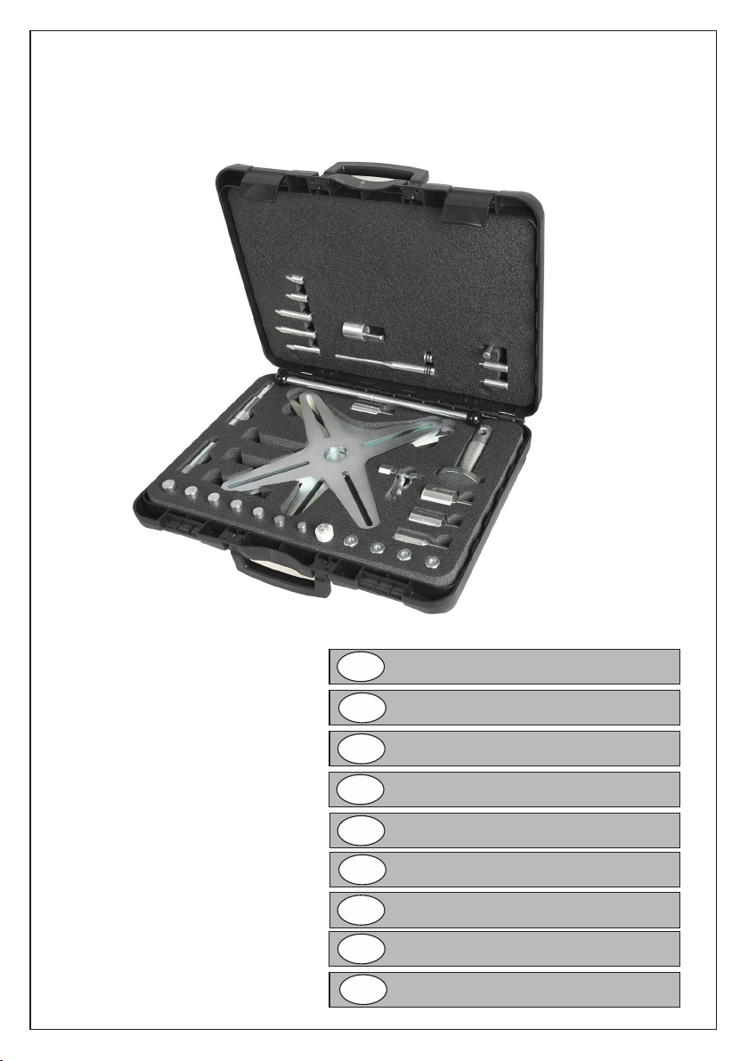
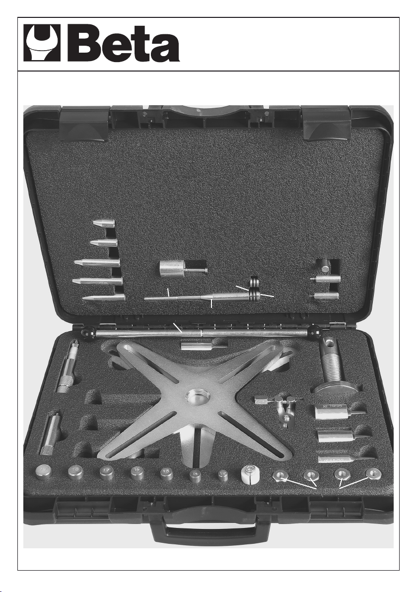
● Tappo lettato di protezione letto interno
● 2 elementi di centraggio / tensionamento per il
cuscinetto guida o il foro dell’albero motore
● Centratore con guida e elemento di tensionamen
to
● 6 diverse bussole coniche per allargare i 2 ele
menti di centraggio / tensionamento
● 3 perni di centraggio di svitamento con diversi
diametri per il cuscinetto guida
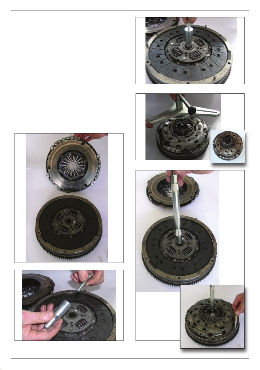
CENTRAGGIO DISCO FRIZIONE:
Per un corretto montaggio della trasmissione e un
corretto funzionamento della frizione la centratura del
disco è fondamentale.
Un corretto centraggio consiste, durante le fasi di
montaggio, nell’inserimento accurato del centratore del
disco frizione. In questo modo si minimizza il rischio di
danneggiamento del disco frizione.
POSSIBILI UTILIZZI DEL PERNO DI
CENTRAGGIO UNIVERSALE:
Il centratore universale è stato ideato per un’applicazione
universale su tutte le autovetture.
Normalmente si trova un cuscinetto di guida nel foro
dell’albero motore il cui diametro interno è più piccolo di
quello del mozzo.
La particolarità di questo centratore è che può essere
utilizzato anche quando manca il cuscinetto di guida.
In questi casi il diametro interno del foro dell’albero
motore può essere più grande di quello del mozzo.
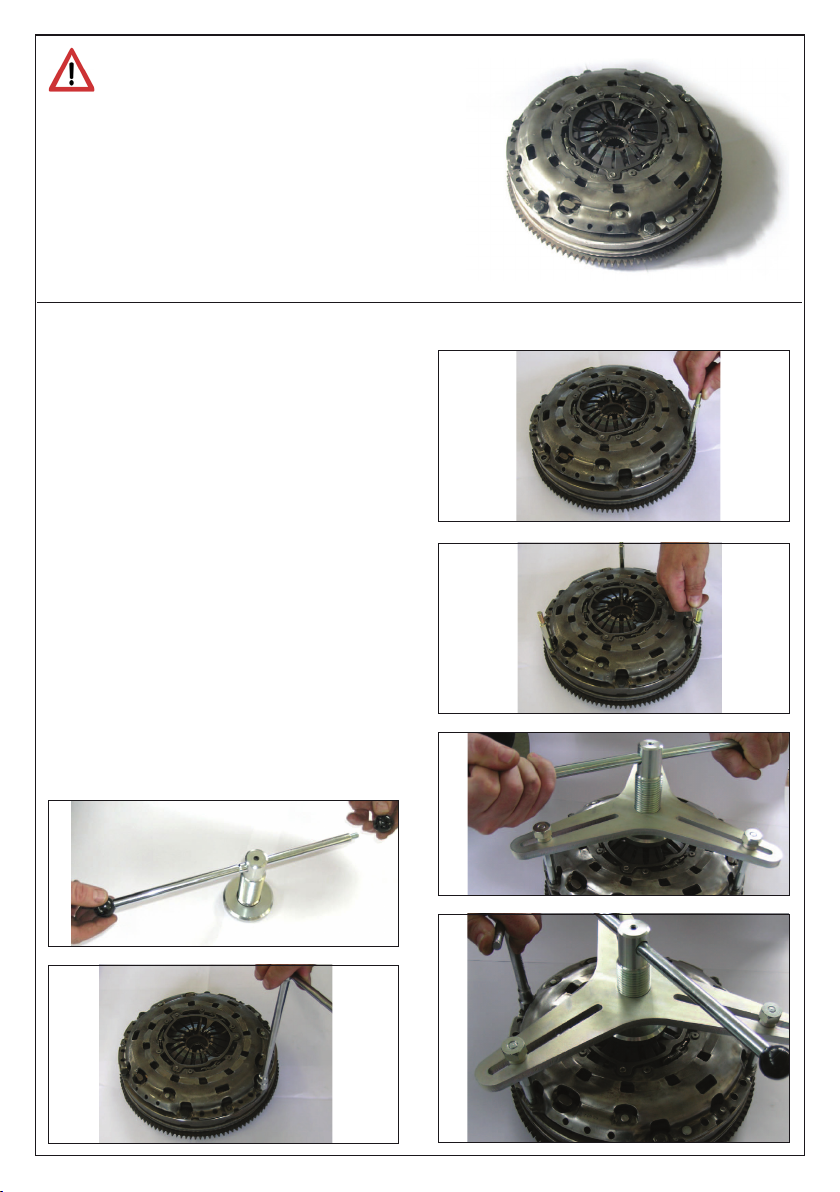
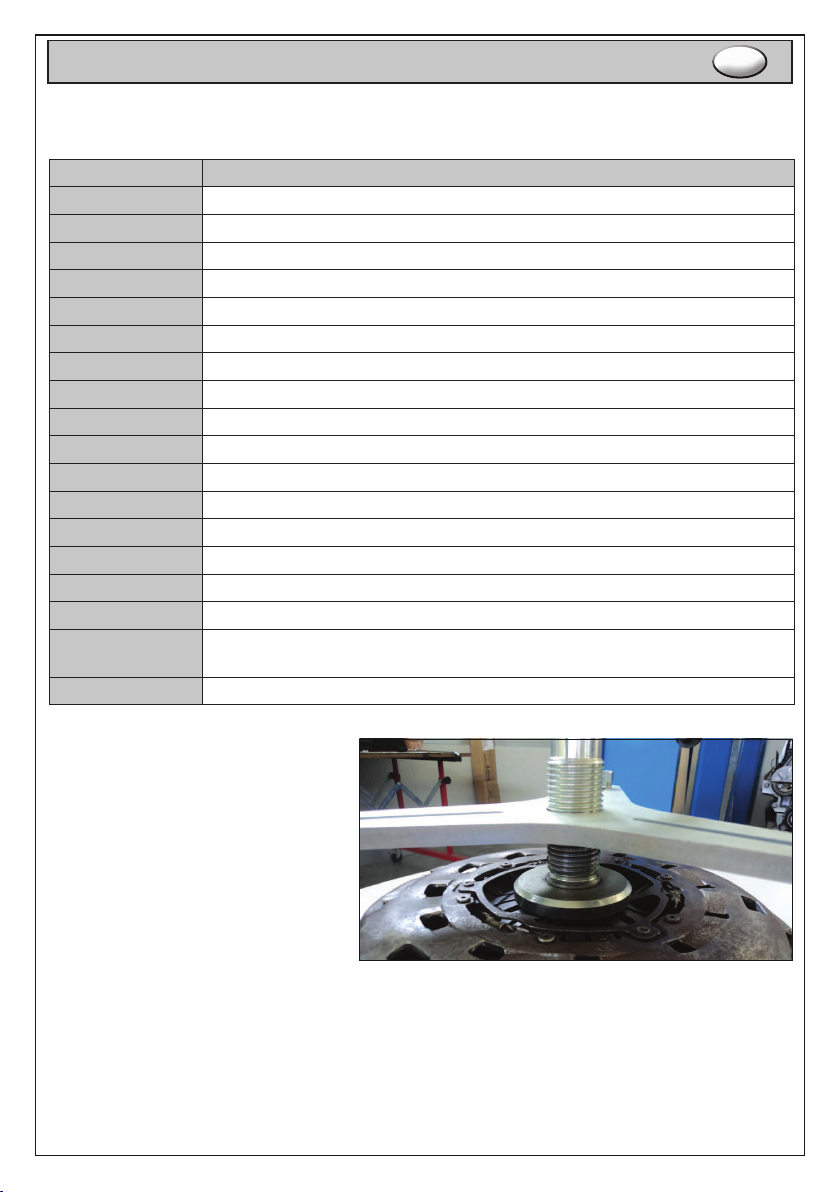
La scelta del perno di centraggio / centratore
da utilizzare è in funzione del diametro interno
del cuscinetto di guida / foro dell’albero motore,
e della distanza tra il cuscinetto guida / foro
dell’albero motore e il prolo del mozzo del disco
frizione.
È possibile utilizzare i vari componenti combi-
nandoli tra loro per trovare il perno di centraggio
adatto.
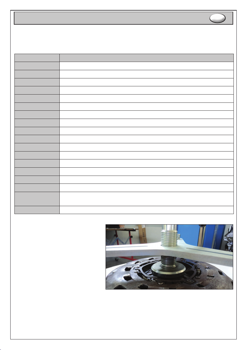
Se non viene utilizzato nessun perno di centrag-
gio avvitare il tappo lettato di protezione del
letto interno, in modo tale da proteggere il letto
da sporco ed eventuali danni.
Denire gli elementi di centraggio e tensiona-
mento da utilizzare in base all’altezza della guida
dell’albero motore e del mozzo del disco frizione.

8
INSTRUCTIONS FOR USE EN
PECIAL KIT SUITABLE FOR SAC CLUTCHES, CENTERING
INCLUDED
COMPONENTS
Beta item
number Description Beta item
number Description
VN952 Bush with screw assembled VN933 Ø 15 centering
VN949 Front centering Ø11.85 VN927 Ø 15/23 centering
VN950 Front centering Ø11.85 VN938 Ø 15/26.5 centering BMW clutches
VN951 Front centering Ø14.85 VN928 Ø 15/28 centering
VN943 Conical centering Ø15x30 VN929 Ø 15/34 centering
VN944 Conical centering Ø15x40 VN934 Ø 16 centering
VN945 Conical centering Ø15x67 VN935 Ø 17 centering
VN946 Conical centering Ø15x75 VN936 Ø 18 centering
VN947 Conical centering Ø18x67 VN937 Ø 19 centering
VN948 Centring Ø15.5 with OR assembled VN925 M6 pin
VN948+
VN955+
VN956+
VN953
Conical centering Ø18x75 VN924 M7 pin
Centring Ø19.8 with OR assembled VN923 M8 pin
Push rod Ø17.8 VN922 Spreader
Central screw M8x170 VN930 Ø 12 spacer in Teon
VN920 3-arms plate VN942 Centring handle
VN921 4-arms plate VN940 Ø 12 complete handle with sphe-
rical knob
TCE 8x45 screw VN941 Ø 20 x handle
VN931 Ø 12 centering VN926 Knob
VN932 Ø 14 centering VN939 Punched pin

9
INSTRUCTIONS FOR USE EN
Nowadays more and more cars mount SAC clutches (Self Adjusting Clutch):
Brand Model
Alfa romeo 147 - 159 - 166 - Brera - Spider
Audi A3 - A4 - A6 - A8 - TT
Bmw 320 - 330 - 520 - 530
Citroën C-Crosser
Fiat Ulisse - Croma - Ducato - Bravo - Stilo
Ford Mondeo - Galaxy - Transit - S-Max - Focus C-Max
Hyundai H-1 - I30 - Santa Fè - Sonata - Tuscon
Lancia Delta - Thesis - Phedra
Mercedes C - E - CLS - S - CLK - SLK - SL
Mitsubishi Grandis - Outlander
Opel Vivaro
Peugeot 4007
Renault Espace IV - Laguna - Laguna II - Laguna III - Trac II - Vel Satis
Seat Altea - Leon - Toledo II
Skoda Octavia - Superb
Vauxhall Vivaro
Volkswagen Eos - Golf IV - Golf V - Golf V Plus - Jetta II - Multivan T5 - Passat - Passat CC - Scirocco - Touran
- Transporter V
Volvo Volvo S40 II - V50
APPLICATION:
These clutches are dened self-adjusting,
because due
to a self-adjusting device, they balance the
clearance
caused to the wearout of the disk clutches
and the pedals
do not become hard.
This grants a long life and an increasingly
comfort.
SAC-Kupplung ist an ihren 2 oder 3 gelben Schnallen erkennbar.

10
During clutches’ mounting operation, it is
necessary to give special attention. A wrong
installation can cause clutch bell deformations
or a loss of regulation.
Consequently warranty replacements become difcult
to recognise because damages can occur due to a bad
mounting.
To avoid this situation and to grant a right assembling and
disassembling of these SAC clutches, it is necessary to
use a special tool.
DISMOUNTING:
The usage of this special clutch tool is basic also to
dismount SAC clutches. In fact if we try to dismount a
SAC clutch, the clutch will unadjust, causing problems
during mounting operations, have a shorter life and cause
a lot of vibrations.
Follow these instructions:
● Mount the handle into the main threaded shaft, locking the
picture 1.
● Unscrew the 3 screws at 120° (or 4 screws at 90° g. 2).
● Mount the suitable screws M6 or M7 or M8 (legs) supplied in
this set (g. 3 and 4);
● Install the special clamp tool (3 or 4 shanks) and lock it with
the M8 locking knobs
● Rotate the special tool’s handle to compress the cup spring
totally (g. 5).
● Unscrew now the remaining ywheel locking screws (g. 6).
● Remove the M8 locking knobs from the special tool, then the
special tool and the three legs.
● Now the pressure plate is raised and the clutch bell touches
the ywheel, becoming easy to unscrew and
remove the clutch (g. 7).
1
2
3
4
5
6

11
MOUNTING:
● Put the plate and the clutch mechanism on the ywheel;
● Centre the disk clutch using one of the suitable tool supplied
(g. 8 - 9 - 10 - 11).
● Insert the three legs with the right threading but do not
tighten, otherwise you can damage the SAC system.
● Install the special clamp tool and lock it with the M8
locking knobs.
Please note that the bell is not connected to the ywheel.
● Rotate the special tool’s handle to compress the cup spring
totally; Now the bell is close to the ywheel.
● Place and tighten the clutch’s locking screws to the ywheel.
● Release the pressure of the tool, and remove all parts.
● Mount now the remaining three screws and nish the
operation.
7
8
9
10
11
Pressure plate
Flywheel
Plate

12
● Protection threaded plug for internal thread
● 2 centering elements / tensioning for the guide
bearing or hole of the driving shaft
● Aligner with guide and tensioning element
● 6 different conic bushes to enlarge the 2 centering
/ tensioning elements
● 3 unscrewing pins with different diameters for the
guide bearing
CENTERING THE CLUTCH DISK:
For a correct assembly of the transmission and a
right functioning of the clutch, the disk centering
is fundamental.
A correct centering during the assembly phases
means to insert accurately the aligner of the
clutch disk. In this way the risk to damage the
clutch disk is minimal.
POSSIBLE USES OF THE UNIVER-
SAL PIN:
The universal aligner has been designed for a
universal application on all vehicles.
Usually the guide bearing is in the hole of the
driving shaft whose internal diameter is smaller
than the hub diameter.
This aligner is very particular: in fact, it may be
used when there is not the guide bearing. In the-
se cases the internal diameter of the driving shaft
hole may be larger than the hub diameter.
The choice of the pin /aligner to use depends on
the internal diameter of the guide bearing / hole
of the driving shaft and on the distance between
the guide bearing / hole of the driving shaft and
the prole of the disk clutch hub.
It is possible to use various components combi-
ning them to nd the suitable pin.
If no pin is used, screw the protection threaded
plug of the internal thread to protect the same
thread from dirty substances and possible dama-
ges.
Dene the centering and tensioning elements to
use according to the height of the driving shaft
guide and clutch disk hub.

13
MODE D’EMPLOI F
COMPLETE EMBRAYAGES KIT DE CENTRAGE
COMPOSANTS
Beta code Description Beta code Description
VN952 Bague avec vis assemblée VN933 Centrage Ø 15
VN949 Centrage antérieur Ø11,85 VN927 Centrage Ø 15/23
VN950 Centrage antérieur Ø13,85 VN938 Centrage Ø 15/26.5 embrayages
BMW
VN951 Centrage antérieur Ø14,85 VN928 Centrage Ø 15/28
VN943 Centrage antérieur Ø14,85 VN929 Centrage Ø 15/34
VN944 Centrage conique Ø15x40 VN934 Centrage Ø 16
VN945 Centrage conique Ø15x67 VN935 Centrage Ø 17
VN946 Centrage conique Ø15x75 VN936 Centrage Ø 18
VN947 Centrage conique Ø18x67 VN937 Centrage Ø 19
VN948 Centrage Ø15,5 avec joints
toriques
assemblés
VN925 Goujon M6
VN948+
VN955+
VN956+
VN953
Centrage conique Ø18x75 VN924 Goujon M7
Centrage Ø19,8 avec joints
toriques assemblés VN923 Goujon M8
Embout Ø17,8 VN922 Écarteur
Vis centrale M8x170 VN930 Expanseur Ø 12 de résine
VN920 Plaque à 3 bras VN942 Poignée de centrage Ø 20
VN921 Plaque à 4 bras VN940 Poignée Ø 12 avec pommeaux
sphériques
---------- Vis TCE 8x45 VN941 Poignée xe Ø 20
VN931 Centrage Ø 12 VN926 Poignée
VN932 Centrage Ø 14 VN939 Goujon percé

14
MODE D’EMPLOI F
Aujourd’hui les voitures ont de plus en plus des embrayages SAC (Self Adjusting
Clutch):
Marque Modèle
Alfa romeo 147 - 159 - 166 - Brera - Spider
Audi A3 - A4 - A6 - A8 - TT
Bmw 320 - 330 - 520 - 530
Citroën C-Crosser
Fiat Ulisse - Croma - Ducato - Bravo - Stilo
Ford Mondeo - Galaxy - Transit - S-Max - Focus C-Max
Hyundai H-1 - I30 - Santa Fè - Sonata - Tuscon
Lancia Delta - Thesis - Phedra
Mercedes C - E - CLS - S - CLK - SLK - SL
Mitsubishi Grandis - Outlander
Opel Vivaro
Peugeot 4007
Renault Espace IV - Laguna - Laguna II - Laguna III - Trac II - Vel Satis
Seat Altea - Leon - Toledo II
Skoda Octavia - Superb
Vauxhall Vivaro
Volkswagen Eos - Golf IV - Golf V - Golf V Plus - Jetta II - Multivan T5 - Passat - Passat CC - Scirocco - Touran
- Transporter V
Volvo Volvo S40 II - V50
APPLICATION:
Ces embrayages sont auto réglables,
parce que grâce au mécanisme de réglage
automatique, compensent le jeu croissant
qui se crée à cause de l’usure du disque de
l’embrayage.
Ce dispositif garantie, pratiquement, une
force de débrayage constante dans le temps
(le pédale d’embrayage ne devient pas plus
dur quand l’usure du disque de l’embrayage
augmente), et un accroissement du confort.
Les embrayages SAC sont caractérisés visuellement par la pré-
sence de quelques (2 ou 3) pinces jaunes présentes sur le mé-
canisme.

15
l faut prêter beaucoup d’attention pendant
l’assemblage de ces embrayages, car un
montage incorrect pourrait déformer la
cloche du mécanisme de l’embrayage ou
causer une perte de réglage du même.
Cela donne lieu à la difculté de reconnaître en ga-
rantie les pièces dont le mal fonctionnement est causé
par des erreurs de montage.
Pour éviter ces inconvénients, le correct montage et
démontage de ces embrayages SAC, doit être effec-
tué avec un outil spécial.
DÉMONTAGE:
L’utilisation de l’outil spécial est fondamentale aussi pour démonter
les embrayages SAC. En effet, si vous essayez de démonter un
embrayage SAC sans son outil, cet embrayage perdrait son réglage
et causerait des problèmes de fonctionnement pendant le montage
suivant.
Le procédé est:
● Montez la poignée dans l’arbre leté principal g. 1.
● Dévissez les trois vis trois vis à 120° ( ou 4 vis à 90°, g. 2).
● Montez le convenable vis M6 ou M7 ou M8 (jambes) fournies
dans cette kit (g. 3 et 4).
● Appliquez l’outil spécial et positionnez les trois écrous pour
le bloquer .
● Tournez l’outil spécial en actionnant le ressort à godet (g. 5).
● Dévissez les vis de serrage restantes du mécanisme embraya
ge au volant (g. 6).
● Enlevez les écrous de l’outil spécial. Enlevez l’outil spécial
et les trois écarteurs. Maintenant vous pouvez démonter
l’embrayage.
● Maintenant, le plat de pression s’est soulevé et la cloche du
mécanisme d’embrayage est à butée sur le volant. Mainte
nant, le serrage des vis, n’entraîne aucun forcement (g. 7).
1
2
3
4
5
6

16
MONTAGE:
● Posé le disque et le mécanisme d’embrayage au volant.
● Centrez le disque embrayage avec son outil (g. 8 - 9 - 10
- 11).
● Introduisez les trois vis (écarteurs) avec le letage approprié
sans les serrer, mais en les portant à butée. Notez comme
la cloche du mécanisme embrayage est éloignée du volant.
● Faire pivoter l’outil spécial la poignée pour comprimer
le ressort totalement; Notez comme la cloche du mécansme
embrayage est éloignée du volant.
● Serrez les vis du mécanisme au volant, dans ces conditions,
il faudrait des pressions qui risqueraient d’endommager le
système de la SAC.
● Enlevez l’outil spécial et détachez-le des trois vis (écarteu
rs), avec ses écrous.
● Montez les autres trois vis de xation et serrez.
7
8
9
10
11
Plateau
d’embrayage
Volant
Disque

17
● Bouchon leté pour la protection du let intérieur
● 2 éléments de centrage / tensionneur pour le
palier de guidage ou le trou de l’arbre moteur
● Centreur avec guide et élément tensionneur
● 6 différentes douilles coniques pour écarter les
2 éléments de centrage / tensionneur
● 3 goujons de centrage et dévissage avec
diamètres différents pour le palier de guidage
CENTRAGE DISQUE D’EMBRAYAGE:
Pour un assemblage correct de la transmission
et un fonctionnement correct de l’embrayage, le
centrage du disque est essentiel.
Pour un bon centrage pendant les phases d’as-
semblage, introduire soigneusement le centreur du
disque d’embrayage. Ainsi le risque d’endomma-
gement du disque d’embrayage est réduit.
POSSIBLES UTILISATIONS DU GOU-
JON DE CENTRAGE UNIVERSEL:
Le centreur universel a été conçu pour une appli-
cation universelle sur toutes les voitures.
Normalement dans le trou de l’arbre moteur il y a
un palier de guidage, dont le diamètre intérieur est
plus petit de celui du moyeu.
Ce centreur peut être utilisé aussi en absence
du palier de guidage. Dans ces cas le diamètre
intérieur du trou de l’arbre moteur peut être plus
grand de celui du moyeu.
Le choix du goujon de centrage / centreur à
utiliser dépend du diamètre intérieur du palier de
guidage / trou de l’arbre moteur et de la distance
entre le palier de guidage / trou de l’arbre moteur
et le prol du moyeu du disque d’embrayage.
Vous pouvez combiner les différents compo-
sants pour trouver le goujon de centrage le plus
indiqué.
Si vous n’utilisez aucun goujon de centrage,
vissez le bouchon leté de protection du let
intérieur pour protéger le let de la saleté et
d’éventuels dommages.
Dénir les éléments de centrage et tensionneur à
utiliser conformément à la hauteur de la guide de
l’arbre moteur et du moyeu du disque d’embra-
yage.

18
GEBRAUCHSANWEISUNG D
SACKUPPLUNGSWERKZEUG-SATZ
BESTANDTEILE
Beta code Beschreibung Beta code Beschreibung
VN952 Buchsen mit Schraube VN933 Zentrierdorn Ø 15
VN949 Vorderer Zentrierdorn Ø11,85 VN927 Zentrierdorn Ø 15/23
VN950 Vorderer Zentrierdorn Ø13,85 VN938 Zentrierdorn Ø 15/26.5 für BMW
VN951 Vorderer Zentrierdorn Ø14,85 VN928 Zentrierdorn Ø 15/28
VN943 Konischer Zentrierdorn Ø15x30 VN929 Zentrierdorn Ø 15/34
VN944 Konischer Zentrierdorn Ø15x40 VN934 Zentrierdorn Ø 16
VN945 Konischer Zentrierdorn Ø15x67 VN935 Zentrierdorn Ø 17
VN946 Konischer Zentrierdorn Ø15x75 VN936 Zentrierdorn Ø 18
VN947 Konischer Zentrierdorn Ø18x67 VN937 Zentrierdorn Ø 19
VN948 Zentrierdorn Ø15,5 mit OR VN925 Stift M6
VN948+
VN955+
VN956+
VN953
Konischer Zentrierdorn Ø18x75 VN924 Stift M7
Zentrierdorn Ø19,8 mit OR VN923 Stift M8
Spitze Ø17,8 VN922 Spreizwerkzeug
Zentrierschraube M8x170 VN930 Spann-/Zentrierelement Ø 12
VN920 Spindelträger mit 3-Loch-Teilung VN942 Zentrierdorn mit Führung Ø 20
VN921 Spindelträger mit 4-Loch-Teilung VN940 Griff Ø 12 mit Knöpfen
---------- Schraube TCE 8x45 VN941 Griff Ø 20
VN931 Zentrierdorn Ø 12 VN926 Rändelmutter
VN932 Zentrierdorn Ø 14 VN939 Lochbolzen

19
GEBRAUCHSANWEISUNG D
Mit dem SAC-Kupplungswerkzeug-Satz können SACKupplungen schnell und fach-
gerecht ein- und ausgebaut werden, Passend für nahezu alle SAC-Kupplungen mit
3- und 4-Loch Teilung:
Marke Modelle
Alfa romeo 147 - 159 - 166 - Brera - Spider
Audi A3 - A4 - A6 - A8 - TT
Bmw 320 - 330 - 520 - 530
Citroën C-Crosser
Fiat Ulisse - Croma - Ducato - Bravo - Stilo
Ford Mondeo - Galaxy - Transit - S-Max - Focus C-Max
Hyundai H-1 - I30 - Santa Fè - Sonata - Tuscon
Lancia Delta - Thesis - Phedra
Mercedes C - E - CLS - S - CLK - SLK - SL
Mitsubishi Grandis - Outlander
Opel Vivaro
Peugeot 4007
Renault Espace IV - Laguna - Laguna II - Laguna III - Trac II - Vel Satis
Seat Altea - Leon - Toledo II
Skoda Octavia - Superb
Vauxhall Vivaro
Volkswagen Eos - Golf IV - Golf V - Golf V Plus - Jetta II - Multivan T5 - Passat - Passat CC - Scirocco - Touran
- Transporter V
Volvo Volvo S40 II - V50
ANWENDUNG:
Diese Kupplungen sind selbstnachstellend;
durch einen
Mechanismus von Selbstnachstellung,
kompensieren sie das steigende Spiel, das
sich wegen der Kupplungsscheibeabnut-
zung bildet.
Diese Vorrichtung garantiert eine konstante
Auskupplungskraft in der Zeit, fördert den
Komfort und verlängert die Kupplungsleben-
sdauer.
Le frizioni SAC si riconoscono per la presenza di 2 o 3 mollette
gialle presenti sul meccanismo

20
Bitte während des Einbaus dieser Kupplun-
gen aufmerksam machen; ein unkorrekter
Einbau könnte Verformungen der Glocke
von dem Kupplungsmechanismus oder
einen
Nachstellungsverlust verursachen.
Das ist mit den Schwierigkeit verbunden, die unter
Garantie-Stücke zu erkennen, deren Funktionsstörung
von Einbaufehlern verursacht ist
Um diese Zwischenfälle zu vermeiden, den richtigen
Einbau und Ausbau dieser SAC-Kupplungen durch ein
spezielles Werkzeug durchführen.
AUSBAU:
Es ist absolut erforderlich die Verwendung dieses speziellen
Werkzeugs für den Einbau und Ausbau der selbstnachstellenden
Kupplungen (SAC).
Wenn wir eine SAC-Kupplung ohne das spezielle
Werkzeug auszubauen versuchen, verliert die Kupplung ihre Nach-
stellung mit folgenden Funktionsstörungen während des Einbaus.
Bitte halten Sie sich an diese Anleitungen:
● Den Griff hinein den Knebel montieren (Bezug 1).
● 3 Deckel-Befestigungsschrauben versetzt um 120° heraus
schrauben (4 er Teilung versetz um 90° aufschrauben und
entnehmen, (Bezug 2).
● Passende gelieferten Gewindebolzen M6, M7 oder M8
auswählen und einbauen (Bezug 3 und 4).
● SAC-Spannvorrichtung über die Gewindebolzen führen
(3 oder 4 Arm-Platte) und mit dem Aufnahmegewinde M8
am Spanndorn verschrauben.
● Druckspindel am Knebel einschrauben bis der
Druckpilz auf die Tellerfeder drückt (Bezug 5).
● Nun die restlichen Befestigungsschrauben heraus schrau
ben. Durch Zurückdrehen der Druckspindel wird
nun die Tellerfeder entlastet (Bezug 6).
● 6-kant-Muttern abschrauben und Traverse entnehmen.
● Abschließend die Gewindebolzen entfernen und die
Kupplung entnehmen (Bezug 7).
1
2
3
4
5
6
Other manuals for 1438SAC
1
Table of contents
Languages:
Popular Automobile Accessories manuals by other brands

Prorack
Prorack K554 Fitting Instructions for Basic Carrier

Metra Electronics
Metra Electronics 99-7953 installation instructions

Scosche
Scosche MAGICMOUNT CHARGE instructions

Menabo
Menabo SHADOW T5 Fitting instructions

Mottez
Mottez ZEUS V2 Fitting instructions

Federal Signal Corporation
Federal Signal Corporation SIFMH Installation maintenance and service manual