Betamotor EVO 4t Instruction manual

WORKSHOP MANUAL


WORKSHOP MANUAL 2009


V
betamotor.com
INDEX
INTRODUCTION ...................................................................................................... 1
CHAPTER 1
LUBRICATION CIRCUIT
1 LUBRICATION CIRCUIT .......................................................................... 8
1.1 ENGINE OIL ..................................................................................................... 8
1.2 CHECKING THE ENGINE OIL LEVEL ............................... 9
1.3 CHANGING THE ENGINE OIL .................................................. 9
CHAPTER 2
ENGINE REMOVAL AND REFITTING
2 ENGINE REMOVAL AND REFITTING ................................. 12
2.1 ENGINE REMOVAL .............................................................................. 12
2.2 REFITTING THE ENGINE .............................................................. 19
CHAPTER 3
DISMANTLING
3 DISMANTLING ............................................................................................... 20
3.1 DRAINING THE OIL ........................................................................... 20
3.2 IGNITION ......................................................................................................... 21
3.3 CYLINDER HEAD ................................................................................... 21
3.4 CYLINDER ....................................................................................................... 24
3.5 FLYWHEEL ...................................................................................................... 24
3.6 OIL PUMP (LEFT-HAND CRANKCASE) ................... 25
3.7 CLUTCH ............................................................................................................. 26
3.8 PRIMARY TRANSMISSION ....................................................... 28
3.9 KICKSTART ..................................................................................................... 29
3.10 SHIFTING MECHANISM ........................................................... 29
3.11 OIL PUMP (RIGHT-HAND CRANKCASE) ......... 30
3.12 TIMING SPROCKET ........................................................................ 31
3.13 SPLITTING THE CRANKCASE ........................................... 31
3.14 GEARBOX AND SHIFTING MECHANISM .......... 32
3.15 CRANKSHAFT ........................................................................................ 33
CHAPTER 4
ASSEMBLY
4.1 RIGHT-HAND CRANKCASE ..................................................... 34
4.2 LEFT-HAND CRANKCASE .......................................................... 36
4.3 CLUTCH CASING ................................................................................... 37
4.4 GEARBOX AND SHIFTING MECHANISM ............. 39
4.4.1 Mainshaft ........................................................................................... 39
4.4.2 Layshaft ................................................................................................ 40
4.5 CRANK ASSEMBLY ............................................................................. 42
4.6 CLOSING THE CRANKCASE ................................................... 43
4.7 SHIFTING MECHANISM .............................................................. 44
4.8 TIMING SPROCKET ............................................................................ 46
4.9 OIL PUMPS ................................................................................................... 47
4.10 KICKSTART .................................................................................................. 50
4.10.1 Preassembly of kickstart shaft .......................... 50
4.10.2 Assembling the kickstart ........................................... 51
4.11 PRIMARY TRANSMISSION GEAR ................................ 51
4.12 CLUTCH .......................................................................................................... 52
4.13 FLYWHEEL .................................................................................................. 55
4.14 PISTON AND CYLINDER ......................................................... 56
4.14.1 Measurements and checks ................................... 56
4.14.1.1 Cylinder ....................................................................................... 56
4.14.1.2 Piston .............................................................................................. 56
4.14.2 Fitting ................................................................................................... 58
4.14.2.1 Studs ............................................................................................... 58
4.14.2.2 Piston .............................................................................................. 58
4.14.2.3 Cylinder ....................................................................................... 59
4.15 CYLINDER HEAD COVER ....................................................... 60
4.16 CYLINDER HEAD ................................................................................ 61
4.16.1 Checks ................................................................................................. 61
4.16.2 Fitting ................................................................................................... 62
4.17 VALVEGEAR ............................................................................................... 64
4.17.1 Pre-assembly of camshaft ....................................... 64
4.17.2 Fitting the valvegear ....................................................... 65
4.18 CLUTCH CASING ............................................................................... 68
4.19 IGNITION ...................................................................................................... 70
4.20 FINAL DETAILS ...................................................................................... 71


1
INTRODUCTION
betamotor.com
FOREWORD
This publication is addressed to the user of the motorcycle and to technical assistance staff. It
has been written with the objective of making known, and comprehensible, the operations
involved in the inspection, maintenance and repair of the motorcycle it deals with.
N.B. Read this manual carefully and from start to finish before carrying out any work on the engi-
ne. A good knowledge of all the components that make up the engine, and of all the procedures
to be followed during the various inspection and maintenance jobs, will help to prolong the life
of the engine.
The manual has been made as comprehensive as possible through the addition of diagramma-
tic illustrations that help clarify the subject at hand.
Note for information
Betamotor S.p.A. is committed to a policy of continuous improvement of its products. For
this reason it is possible that you will encounter slight differences between what is stated
in this manual and the vehicle on which you are about to carry out repair and/or mainte-
nance. Betamotor models are exported to numerous countries, where different rules apply
with respect to highway law and homologation procedures. Trusting that you will under-
stand, Betamotor S.p.A. therefore believes that it must reserve the right to make alterations
to its products and technical documentation at any time and without prior notice.
We respect and defend the environment.
Everything we do has repercussions for the the entire planet and its resources. In the in-
terests of the community, Betamotor wants its customers and technical assistance staff to
be aware of the need to adopt procedures for the use of the vehicle and for disposal of its
parts which fully comply with the applicable regulations in terms of environmental pollu-
tion and the disposal and recycling of waste.
SAFETY
Carbon monoxide
• Exhaust gases contain carbon monoxide (CO), which is a poisonous gas. Carbon monoxi-
de can cause loss of consciousness and lead to death.
• If the engine has to be started, make sure that the area is well ventilated. Never start the
engine in an enclosed space.
• Starting the engine in an enclosed space is permissible only if appropriate devices are
used for extracting the exhaust gases.

2
INTRODUCTION
betamotor.com
Petrol
• Petrol is highly flammable and in certain conditions can cause explosions.
• Keep heat sources, sparks and flames well away from the work area.
• Always work in a well-ventilated area.
• Never use petrol as a cleaning solvent. In general, avoid handling it if not strictly neces-
sary.
• Do not use petrol for cleaning components by means of compressed air.
• Keep it well out of the reach of children.
Engine oil
• Engine oil can cause skin diseases if it repeatedly comes into contact with the skin for
prolonged periods.
• If you come into contact with engine oil, wash the affected parts as soon as possible with
soap and water.
• If it comes into contact with the eyes, rinse with plenty of water and consult a doctor.
• If ingested, do not provoke vomiting, in order to avoid inhalation of the product. Consult
a doctor immediately. If it is thought that inhalation of the product has taken place, take
the person concerned urgently to hospital.
• Waste oil contains dangerous substances which are harmful to the environment. When
changing the oil, it is necessary to be equipped for disposing of the waste oil in accordan-
ce with the relevant law.
• Do not dispose of waste oil into the environment.
• Keep it well out of the reach of children.
Coolant
• In certain circumstances the ethylene glycol in coolant is flammable, and its flame is invisi-
ble. If ethylene glycol catches fire, the flame, although invisible, can cause serious burns.
• Avoid bringing coolant into contact with hot components. Such components could be
sufficiently hot to cause it to ignite.
• Coolant (ethylene glycol) can cause skin irritation and is poisonous if ingested.
• If coolant comes into contact with the skin, remove any contaminated clothing or foo-
twear immediately and wash promptly with soap and water. If it comes into contact with
the eyes, rinse with plenty of clean water and consult a doctor immediately. If ingested,
do not provoke vomiting, in order to avoid inhalation of the product. Give the affected
person clean water to drink, take them to hospital urgently and show the product to the
medical staff.
• In case of exposure to high concentrations of fumes, take the affected person into an
unpolluted environment and if necessary call a doctor.

3
INTRODUCTION
betamotor.com
• Do not remove the radiator filler cap when the engine is still hot. The coolant, being under
pressure, can spurt out violently and cause burns.
• Coolant contains dangerous substances which are harmful to the environment. When
changing the coolant, it is necessary to be equipped for disposing of waste oil/coolant in
accordance with the applicable law.
• Do not dispose of coolant into the environment.
• Keep it well out of the reach of children.
Hot parts
• The engine and exhaust system become very hot and retain heat for a considerable time,
even after the engine has been switched off. Wait for them to cool down before handling
these parts or working in areas adjacent to them. In addition, use insulating gloves.
WARNINGS
The information in this paragraph is important in order for the operations carried out on the
motorcycle to be performed without damaging the motorcycle itself.
• Before dismantling, clean the vehicle thoroughly.
• During dismantling, clean all parts and put them away in containers, following exactly the
order of dismantling.
• Always use special tools where necessary and whenever their use is specified.
• Always use adhesives, sealants and lubricants where specified. Follow the recommenda-
tions regarding their technical characteristics.
• Always replace parts such as gaskets, O-rings and safety washers with brand new parts.
• When loosening or tightening nuts or bolts, always start with the largest or from the cen-
tre. Always follow the recommended torque settings.
• Use only original Betamotor spare parts.

4
INTRODUCTION
betamotor.com
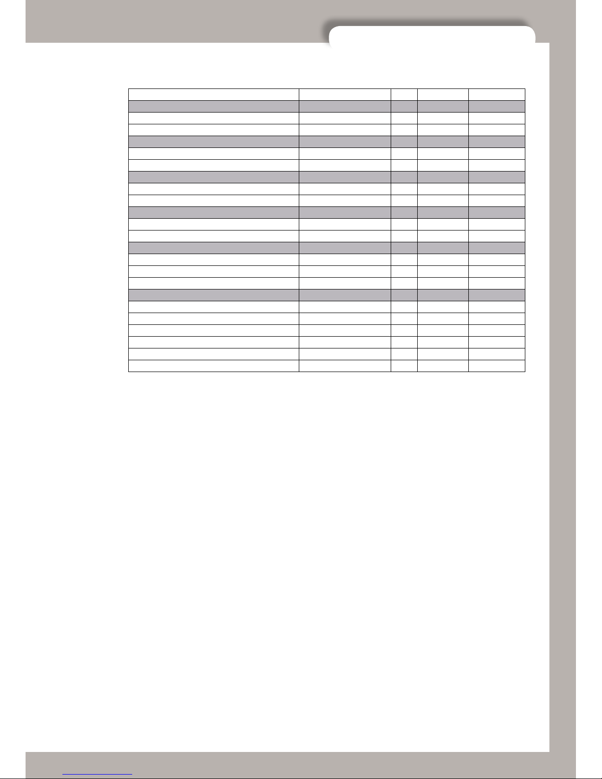
FIXING PART PCS THREAD LOCK TORQUE [NM]
ENGINE FIXING
Engine front fixing 10x1,5L127 [5.8] 1 25
Engine back fixing 10x1.25L100 [5.8] 1 30
Cylinder head fixing 8x1.25L55 [8.8] 1 30
FRAME PARTS
Engine arms to frame 8x1.25L16 [8.8] 4 25
Engine bumper (front fixing) 8x1.25L16 [8.8] 2 20
Engine bumper (back fixing) 8x1.25L20 [8.8] 2 30
Filter box support brackets 8x1.25L20s [10,9] 2 X 25
Footrest brackets 8x1.25L25 [8.8] 4 X 30
Engine retaining plates 6x1L50 [8.8] 2 15
Regulator support 5x0.8L8 [8.8] 2 5
Fixing screws for oil tank and regulator 5x0.8L12 [8.8] 1 5
SWING ARM
Swing arm to frame/engine 16x1,25L255 [5.8] 1 50
Shock absorber to frame 10x1,25L50 [8.8] 1 45
Shock absorber to lever 10x1,25L45 [8.8] 1 45
Lever to swing arm 10x1.5L75 [10,9] 1 45
Connecting rods to lever 10x1.5L125 [10.9] 1 45
Connecting rods to frame 8x1,25L42 [10,9] 2 30
Stand to swing arm 6x1L20 [8.8] 2 X 10
Sliding block chain tightener to swing arm 8x1.25L12s [8.8] 1 10
Chain tightener spring fixing 5x0.8L20 [8.8] 1 5
Chain guide shoe rubber (upper) 6x1L35 [8.8] 1 10
Chain guide shoe rubber (lower) 5x0.8L8 [8.8] 1 5
Sprocket cover 5x0.8L8 [8.8] 2 5
Pipe fastening clamps 5x0.8L6 [8.8] 2 5
FRONT FORK
Triple fork clamp (fixing tubes) 6x1L25 [8.8] 10 10
Handlebar to triple fork camps 8x1.25L30 [8.8] 2 30
Fork adjusting ring nut Speciale 1 25
Head tube nut 18 125
HANDLEBAR DEVICES
Throttle control 4x0.7L12 [8.8] 2 3
Clutch master cylinder 4x0.7L12 [8.8] 2 3
Brake master cylinder 5x0.8L15 [8.8] 2 3
BRAKES
Front brake caliper (upper) 8x1.25L55 [8.8] 1 X 23
Front brake caliper (lower) 8x1.25L35 [8.8] 1 X 23
Rear brake master cylinder to frame 6x1L16 [8.8] 2 12
Brake pedal 8x1.25L20 [8.8] 1 X 10
Brake disk cover 4x0.7L14 [8.8] 2 3
EXHAUST
Silencer to frame (upper) 6x1L25 [8.8] 1 10
Silencer to frame (lower) 6x1L10 [8.8] 1 10
FASTENING BOLT TORQUE SETTINGS - FRAME
5
INTRODUCTION
betamotor.com
FIXING PART PCS THREAD LOCK TORQUE [NM]
AIR FILTER BOX
Air filter box to frame 5x0,8L12 4 5
Filter case cover 5x0,8L12 2 5
COOLING
Radiator to silent block 6x1L10 [8.8] 2 10
Electric fan to radiator 6x1L20 [8.8] 4 10
ELECTRICAL EQUIPMENT
Coil retaining screws 5x0.8L25 [8.8] 2 5
Lights switch 4x0,7L14 [8.8] 2 3
FRONT WHEEL
Front wheel pin 18x1,5 [5.8] 1 50
Disc brake 6x1L25 [8.8] 4 X 10
REAR WHEEL
Rear wheel pin 16x1.5 [5.8] 1 80
Disc brake 6x1L16 [8.8] 4 X 10
Sprocket 8x1.25L33 [8.8] 4 X 23
PLASTICS / TANK
Front mudguard 6x1L16 [8.8] 4 10
Rear mudguard 5x0.8L8 [8.8] 5 5
Headlight mask (upper) 5x0,8L20 [8.8] 1 5
Headlight mask (lower) 5x0,8L30 [8.8] 1 5
Tank panels 5x0,8L8 [8.8] 4 5
Front disc cover (lower screw) 5x0,8L16 [8.8] 1 5

6
INTRODUCTION
betamotor.com
ASSEMBLY COMPONENT QTY THREAD LOCK TORQUE (NM)
VALVEGEAR GROUP
Valve adjuster covers Bolt M6x16 4 10
Camshaft sprocket Screw M6x10 2 10
Water pump cover Screw M6x20 3 10
Carburettor flange Bolt M6x16 2 10
Exhaust flange Screw M6x15 4 10
Movable guide Bolt TTLIC M6x12 1 X 10
Camchain tensioner Bolt M6x16 2 8
Water circuit bleed screw Screw M6x12 1 8
Water circuit drain screw Screw M6x12 1 8
Rocker spindle plug M16x1 2 10
Valve adjuster locknut Nut M6x0.75 4 11
Cylinder head cover Bolt M6x35 4 10
Bolt M6x25 2 10
Bolt M6x55 4 10
Head – Cylinder Bolt M6x25 1 10
CRANKSHAFT GROUP
Crankshaft half, clutch side Nut M18x1.5 1 150
Crankshaft half, flywheel side Nut M14x1.5 1 120
TDC locking bolt Special bolt M8 1 25
CRANKCASE GROUP
RH crankcase – LH crankcase Bolt M6x45 2 10
Bolt M6x60 9 10
RH crankcase – Clutch casing Bolt M6x25 7 10
Bolt M6x55 1 10
Bolt M6x30 2 10
Selector drum bearing retaining bolt Bolt M6x10 2 X 10
Flywheel cover Bolt M6x30 5 10
Bolt M6x35 2 10
Clutch cover Screw M6x20 4 10
Head – Cylinder – Crankcase Stud M10x1.25 4 X 30
Nut M10x1.25 4 30
Oil drainplug M16x1.25 1 20
Oil level plug M16x1.5 1 10
Retaining plate Corteco Special screw M4x8 2 X 3
Oil circuit jet M5x0.75 2 6
IGNITION/STARTING GROUP
Pickup retaining bolt Bolt M6x12 2 8
Stator retaining screw Screw M5x25 3 6
Ramp Bolt M6x20 2 X 8
Kickstart pivot retaining bolt Bolt M8x20 1 25
Sparkplug M10x1 1 10-12
GEARCHANGE GROUP
Detent cam Bolt M6x35 1 X 10
OIL PUMP GROUP
Cover, oil pump LH Screw M6x14 2 10
Cover, oil pump RH Screw M6x20 1 10
Screw M6x15 1 10
Pivot, oil pump idler gear Screw, shallow, M6x25 1 X 10
Intake filter cover, output oil pump M20x1.5 1 15
Intake filter cover, scavenge oil pump M20x1.5 1 15
FASTENING BOLT TORQUE SETTINGS - ENGINE
7
INTRODUCTION
betamotor.com
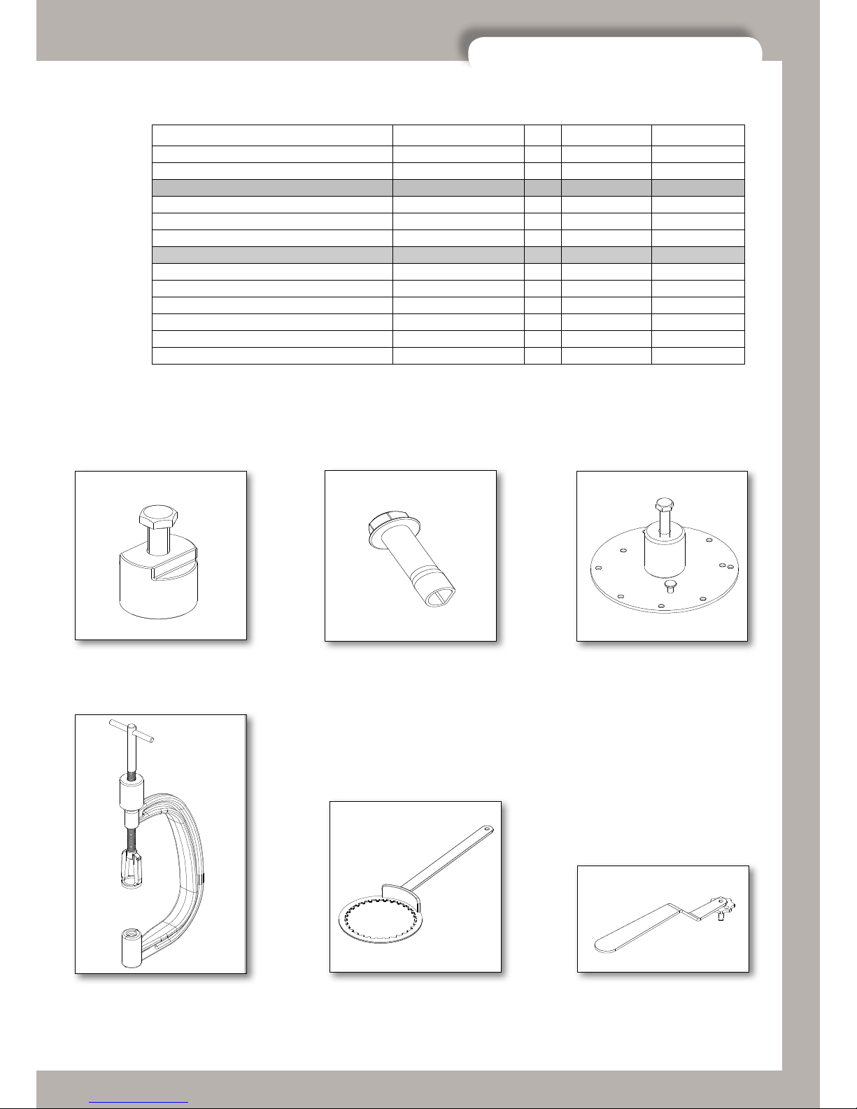
01.00040.000
Flywheel extractor
01.00041.000
Key for water pump shaft
01.00042.000
Crankcase splitter
01.00043.000
Valve spring fitting tool
01.00044.000
Inner clutch hub locking tool
01.00045.000
Carburettor adjusting
spanner
ASSEMBLY COMPONENT QTY THREAD LOCK TORQUE (NM)
Filter cover, output oil pump Screw M6x20 3 10
Oil pressure relief valve Special bolt M12x1.25 1 20
CLUTCH GROUP
Pressure plate Bolt M6x16 6 10
Clutch centre Special nut M14x1.25 1 90
Clutch actuator body. Bolt M6x16 3 10
FRAME – ENGINE
Swing-arm bolt Nut M16 1 90
Stay RH Bolt M8 2 25
Stay LH Bolt M8 2 25
Engine mounting bolt, front Bolt M10 1 25
Engine mounting bolt, lower Nut M10 1 25
Mounting bolt, cylinder head Nut M8 1 30
SPECIAL TOOLS
8
LUBRICATION CIRCUIT
betamotor.com
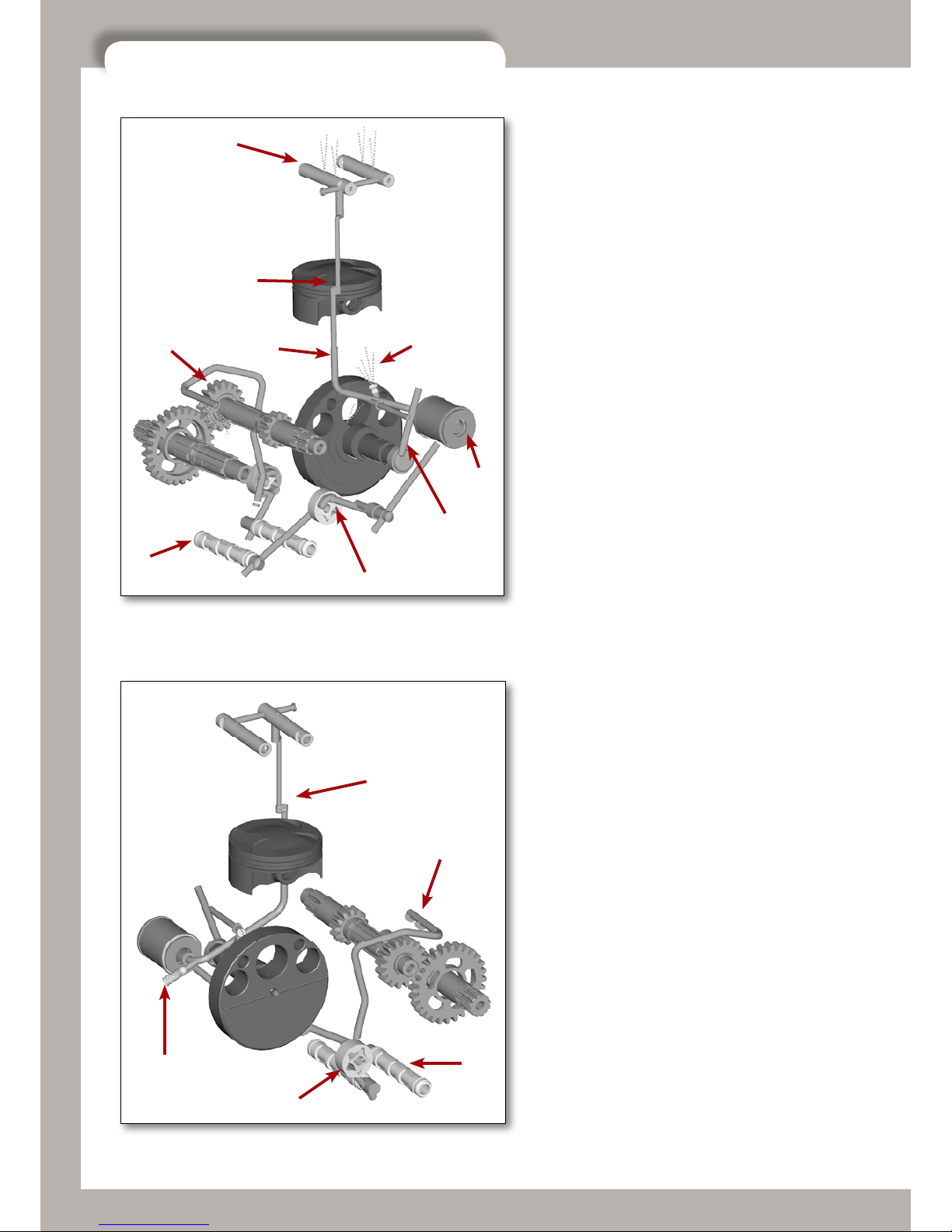
1 LUBRICATION CIRCUIT
The output oil pump (1) draws in oil from the area
at the base of the gearbox through its own mesh
oil filter (2) and then sends it to the paper oil fil-
ter (3). From here the oil, starting from the bypass
valve (4), is directed in three different directions:
by means of a jet (5) it lubricates the piston pin
and takes heat from the crown of the piston; and it
passes through two pipes, one of which (6) takes it
to the crankshaft to lubricate the roller bearing on
the crankpin; the other (7), whose flow is regulated
by a calibrated hole in the cylinder base gasket (8),
feeds the valvegear (9). The oil then returns to the
base of the crank chamber from the piston, the con-
rod assembly and the cylinder walls, and is drawn
in by the scavenge pump (10) through the mesh
filter (11). It is pumped through special jets (12)
and lubricates the transmission gears. The oil in the
cylinder head, however, returns to the base of the
gearbox passing through the timing case and the
inner clutch casing.
1.1 ENGINE OIL
Use only fully synthetic oils of a reputable brand
(BARDAHL XTC60 15W50).
9
8
75
3
6
1
2
12
8
4
10
11
12
9
LUBRICATION CIRCUIT
betamotor.com
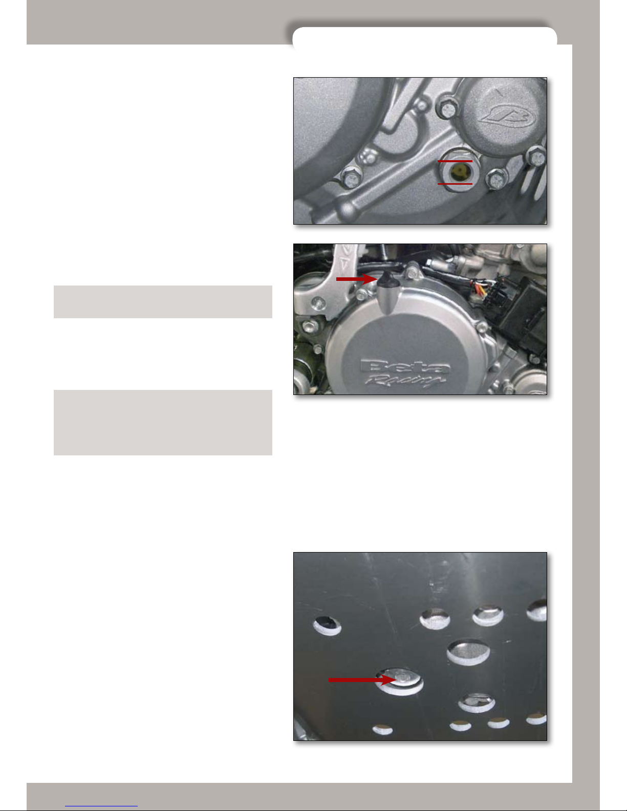
1.2 CHECKING THE ENGINE OIL LEVEL
The engine oil level must be checked when the en-
gine is warm. Run the engine for several minutes
and then switch it off. Place the bike on a flat surfa-
ce in such a way that it is perfectly vertical.
Wait a few minutes and then check the oil level in
the sightglass located in the clutch casing (right-
hand side of the engine). The level must be betwe-
en the limits indicated in the picture.
If necessary, remove the oil filler plug and top up
the level.
N.B. Running the engine with too little oil causes ex-
cessive wear to the engine components.
1.3 CHANGING THE ENGINE OIL
N.B. At each oil change, the mesh filters must be cle-
aned and the paper filter replaced.
N.B. The oil change must be carried out when the
engine is at working temperature. Be careful not to
scald yourself with the hot oil.
After the engine has reached operating temperatu-
re, switch the bike off and stand it upright.
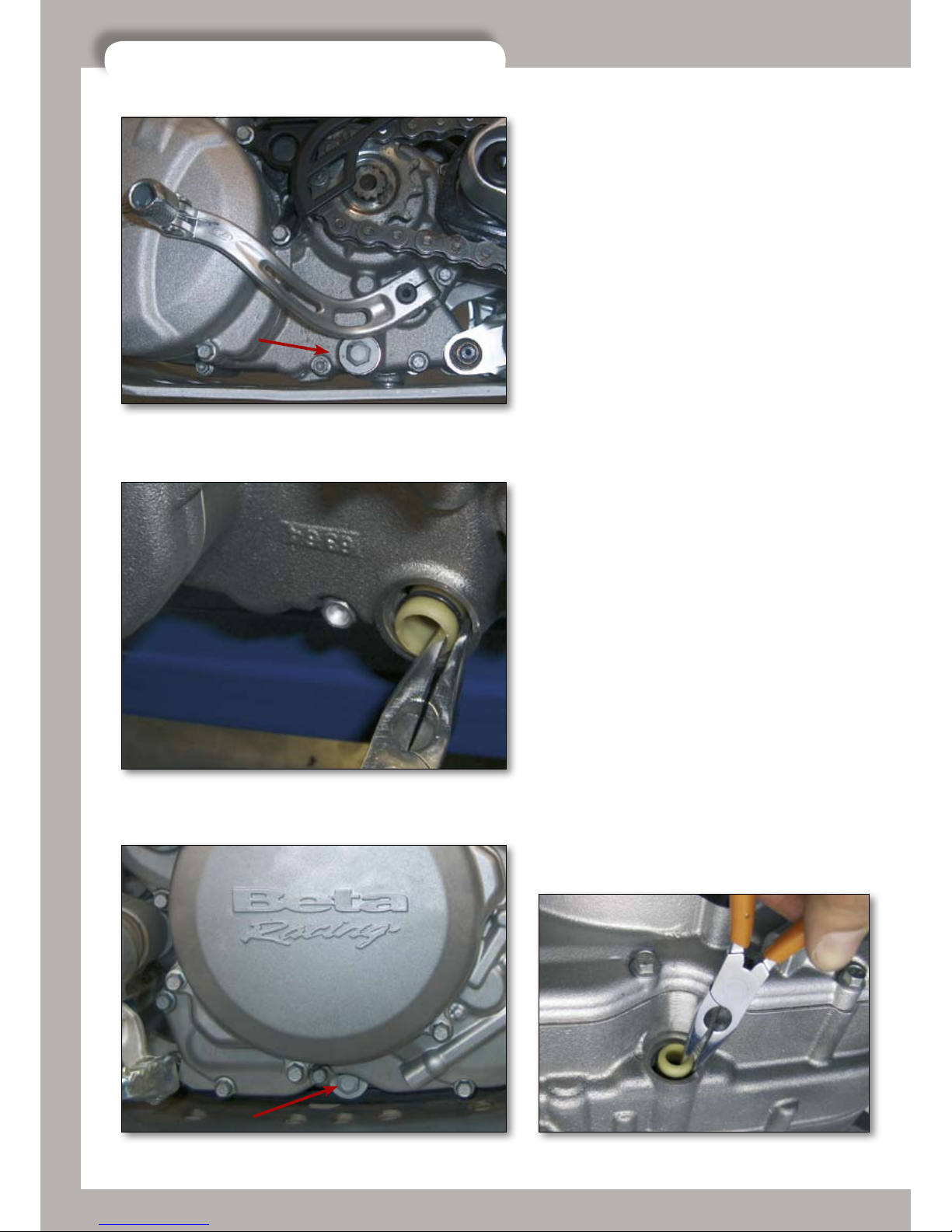
Unscrew the oil drainplug and let all the oil flow out
into a drain pan. Thoroughly clean the magnet on
the drainplug to get rid of the metallic impurities
that it has collected.
MAX
MIN
10
LUBRICATION CIRCUIT
betamotor.com
Unscrew the plug in the left-hand casing and use
pliers to extract the filter. Clean it carefully and blow
it through with compressed air. Check for damage
to the O-rings, and replace them if necessary. Refit
all the parts and tighten the plug to 15 Nm.
Carry out the same procedure for the output mesh
filter, for which the access is via the right-hand en-
gine casing.

11
LUBRICATION CIRCUIT
betamotor.com
Position a container under the bike, near the cover
for the paper filter, and unscrew the bolts on the
filter cover.
Then extract the paper filter using pliers. Check the
condition of the O-ring too, and replace it if neces-
sary.
Change the filter and refit the cover, tightening the
three M6x20 bolts to 10 Nm.
Refit the oil drainplug, tightening it to 20 Nm, and
refill with 0.81 of engine oil (BARDHAL XTC60
15W50).
N.B. If the engine has been opened up for an internal
inspection, the quantity of oil to put in is 0.9 litres.
Finally, tighten the oil filler plug (A) to 10 Nm.
A

12
ENGINE REMOVAL AND REFITTING
betamotor.com
2 ENGINE REMOVAL AND REFITTING
2.1 ENGINE DISASSEMBLING
Deeply clean the whole bike and position it on a
steady stand.
Disassemble front fender.
Disassemble silencer.
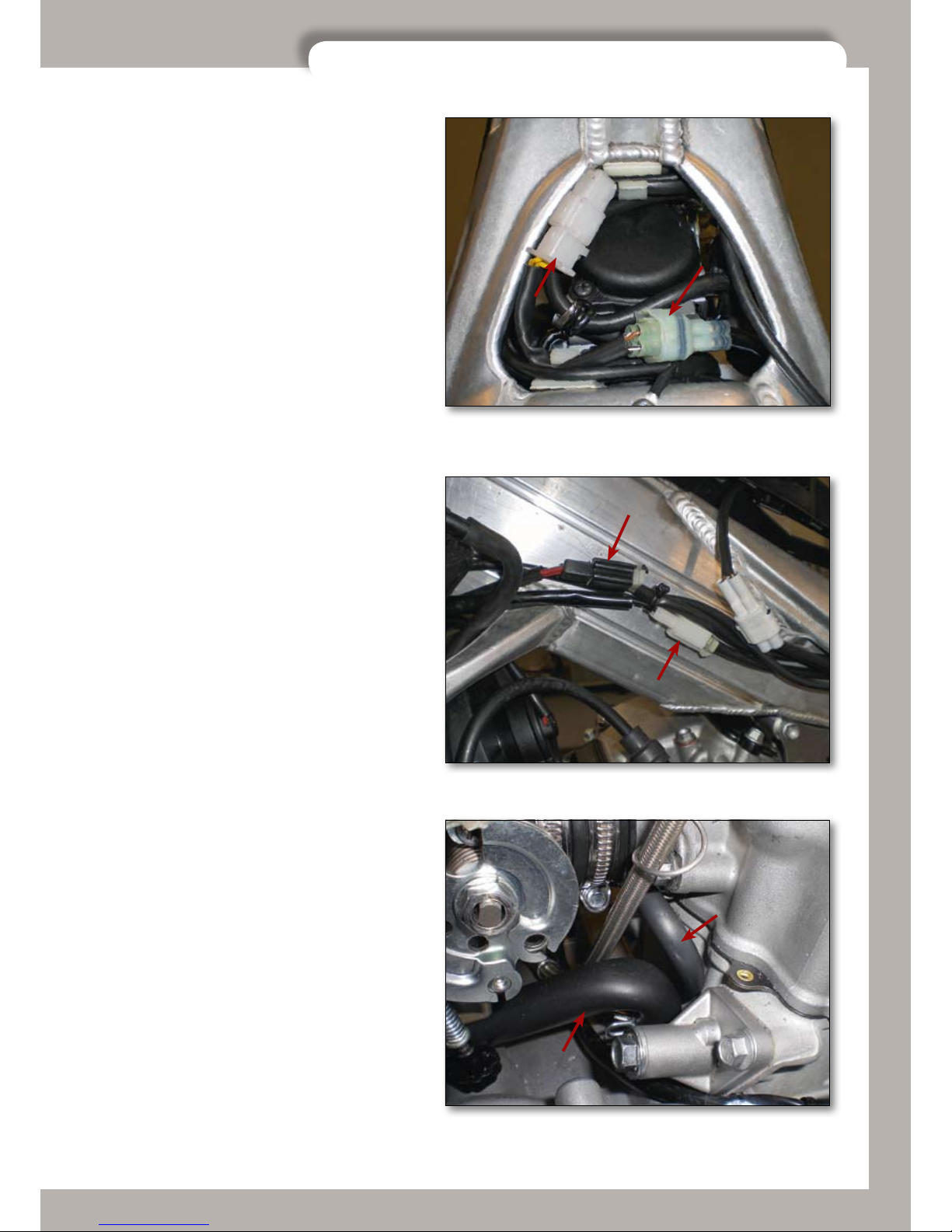
Unhook the two springs located in front of the en-
gine head (A). Then disassemble the exhaust col-
lector (B).
Disassemble the bumper.
B
AA
13
ENGINE REMOVAL AND REFITTING
betamotor.com
Disconnect the electrical connectors A and B loca-
ted over the carburettor.
Disassemble left panel and disconnect connectors
C and D of the electric fan and bulb.
Disconnect the coil from radiator and unplug the
pipe from the spark plug.
Disconnect oil vapour hose (E) and Hot Start hose
(F).
B
C
F
D
E
A

14
ENGINE REMOVAL AND REFITTING
betamotor.com
Make sure that the fuel petcock is closed (lever
in position “C”).
Disassemble the rear brake oil tank by un-
screwing the fixing screw.
Loosen the carburettor fixing clamp.
This manual suits for next models
1
Table of contents
Other Betamotor Motorcycle manuals


