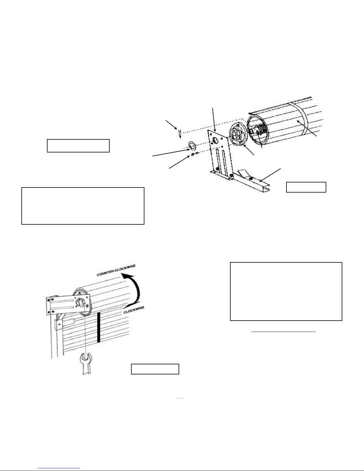
STEP 10. INSTALLING OPTIONAL TENSION ADJUSTER
Slide DOOR TRACK ASSEMBLY with DOOR BRACKET onto AXLE ASSEMBLY. (TENSION
ADJUSTER is factory assembled with DOOR BRACKET.) Attach spring to TENSION
ADJUSTER into the offset hole with a 5/16” x 3/4” bolt and washer. Slide large WASHERS
onto AXLE. Install 1/8” diameter x 2-1/2” COTTER PINS through holes provided in AXLE.
Install 1/4” diameter BALL LOCK PINS through (1) hole into TENSION ADJUSTER.
Return to steps 6, 7, 8, & 9.
STEP 11. ADJUSTING SPRING TENSION USING TENSION ADJUSTER
Doors with openings 9’0” wide or less use
only one tension adjuster located on the left
side with left door bracket assembly. Right
side will be installed with a standard right
door bracket assembly.
WARNING
SINCE SPRINGS ARE UNDER EXTREME TEN-
SION. NEVER REMOVE SPRING FASTENERS.
KEEP A SECURE HOLD ON THE DOOR AND
BOTTOM BAR WHEN ANY TENSION ADJUST-
MENTS ARE MADE OR WHEN DOOR STOPDS
ARE NOT SECURELY ATTACHED THE DOOR
ROLL WILL TRY TO UNROLL RAPIDLY AND
CAN CAUSE SEVERE INJURY.
ADJUSTING TENSION
Place 1-3/4” wrench or channel lock
pliers onto 1-3/4” hex of TENSION
ADJUSTER. Hold that position to
retain tension. Remove ball lock pin.
Turn TENSION ADJUSTER to next
hole alignment in TENSION
ADJUSTER. To increase tension,
turn wrench counter-clockwise or
turn clockwise to decrease tension.
Replace ball lock pin. Retry DOOR
for proper tension. Repeat operation
until tension is satisfactory to the
customer. Install a 5/16” x 3/4” hex
head bolt through bracket into
TENSION ADJUSTER.
DOOR BRACKET
SEE STEP 8 FOR PRE-
TENSION OF DOOR SPRING
1/8” DIA. X 2-1/2” LG. COTTER PIN
2” I.D. X 3” O.D.WASHER
1/4” DIAMETER BALL LOCK PIN DOOR TRACK
FIGURE 10
TENSION ADJUSTER (Pre-assembled to bracket)
DOOR AXLE ASSEMBLY
DOOR CURTAIN
FIGURE 11
Page 8 12/31/03