BETE XA Series Operating instructions

Visit BETE.com for comprehensive spray nozzle tools, case studies and literature.
413.772.0846 sales@bete.com
1
TROUBLESHOOTING:
BETE XA NOZZLES
XA COMPONENTS
BETE XA nozzles consist of a body, a spray
set-up, hardware assemblies, and optional
mounting devices.
The body is the base
component. It contains the
connection ports for the
liquid and air supplies, a
connection for the spray
set-up, and may contain a
connection for a hardware
assembly.
The spray set-up consists of an air cap
and a uid cap. The air cap and uid cap
combination control the spray performance,
including ow rates and spray pattern.
Optional hardware assemblies allow
either shutoff or shutoff and clean-out of
the uid cap. Hardware assemblies may be
actuated manually (B, C, and D hardware)
or pneumatically (E or F hardware). Not all
bodies accept all hardware.
Mounting devices offer a method of holding
the nozzle in a xed location. They attach to
the uid cap.
Operation of the air cylinder of the E or F
hardware requires a minimum air pressure
of 30 psi to retract the rod. Failure to provide
sufcient air pressure is one of the most
frequent causes of poor nozzle performance.
The E or F hardware feature a built-in air
cylinder which allows liquid ow to be shut
off at the nozzle tip, resulting in precise,
intermittent application of liquid. When
air pressure is released a spring causes the
cylinder to return to the closed position.
For the F clean-out option, the pin pushes
accumulated material from the liquid orice
as it returns. The clean-out pin is not able
to remove material from the orices in the
air cap.
Standard seal materials limit the XA to use
at temperatures less than 400°F. Materials
allowing use at higher temperatures are
available by special request. All spray set-ups
t on all bodies. All spray set-ups may be
used with hardware, however the available
hardware is limited by the chosen body style.
The 00 and 03 bodies can accept all
hardware assemblies. Complete nozzle
assemblies initially sold with manual
The BETE XA series is a multi-component
air atomizing system. The XA system was
designed to allow the swift exchange and
replacement of caps, bodies and tips. The
system provides a wide range of spray
patterns and simplies maintenance. The XA
series assemblies may consist of anywhere
from 6 to 11 parts.
Please be certain to read all instructions
carefully before assembling or disassembling
the nozzle. Damage to these assemblies can
occur if these procedures are not followed.
OPEN
CLOSED
hardware (B, C, or D) may be upgraded in the
eld to automatic hardware (E or F).
The square 00 body with E or F hardware
requires two separate air lines and more
complex piping.
The 01 body features a consolidated air inlet
combining both the atomizing air and cylinder
air in a single line, resulting in simplied piping
layouts. The 01 body can be used only for
applications where the atomizing air pressure
is ABOVE 30 psi.
The 01 and 02 bodies simplify external air line
connections by xing the orientation of the air,
liquid and cylinder inlets.
The 01 and 02 bodies may only be used with the
E or F hardware.
The 02 body requires two separate air lines,
one to supply atomizing air and one to supply
operating air to the cylinder. The two air lines
allow the use of atomizing air at pressures both
BELOW and ABOVE 30 psi, while maintaining
the minimum 30 psi to the cylinder.
The 05, 06, 07, and 08 bodies do not accept any
hardware.
The XA10 and XA11 bodies have a built in
air-operated cylinder. This integral cylinder
provides a smaller prole for use where space
is limited.
1. Adequately size air and liquid lines
to maintain required pressures at each
nozzle. (consult air and water ow charts
on page 4)
16. During installation, ensure the liquid
and air supplies are connected to the
correct port. The words “LIQUID” and
“AIR” are
stamped on
the bodies
adjacent to the
correct port.
4. To maintain adequate air pressure (30
psig min) for cylinder operation, use the
02 body if atomizing air pressure to the
nozzle is expected to fall below 30 psi.
2. Each siphon nozzle must have a
separate liquid feed line from the
reservoir.
9. To maintain atomization during
startup and shutdown, always turn on
air rst and turn off air last.
10. Multiple nozzle
installations are especially
sensitive to line sizes and
lengths. Size air and liquid
lines generously and avoid
large numbers of nozzles
(no more than 6) on a single
branch.
11. Humidication requires
high air/ liquid ratios,
usually in the range of 2 to
4 SCFM per gallon per hour,
to produce droplets small
enough for evaporation.
14. For viscosities greater
than 150 cP, consider using
one of the EF setups.
6. Flush out air and liquid lines before
connecting nozzles to clear out loose
material which could cause pluggage.
7. Install air and liquid pressure gauges
close to the nozzle location(s) to allow
accurate control of pressures.
3. For extreme temperatures and a range
of chemicals, consult chart of options for
special gaskets, sealants and Loctite®
adhesives.
8. As a general rule avoid spraying
counter-current to reduce contamination
problems from process environments.
12. Maximum operating rate for air
cylinders is 3 cycles per second.
Maximum pressure is 125 psi.
13. In dirty process environments, a
purge air pipe surrounding the nozzle
can reduce contamination problems.
15. Whenever ow rate accuracy is
critical, a positive displacement metering
pump or ow controller should be used.
5. For severe chemicals and abrasive
liquids, consult factory for optional
nozzle materials.
CAUTION
CAUTION
CAUTION
CAUTION
CAUTION
CAUTION
INSTALLATION TIPS

Visit BETE.com for comprehensive spray nozzle tools, case studies and literature.
413.772.0846 3
sales@bete.com 413.772.0846
2
SPRAY SET-UP BODY STYLES & SEALS HARDWARE ASSEMBLIES
*For extensions, A hardware is
standard; E and F hardware may
be provided on an application
specic basis. Loctite is a registered trademark of Henkel Corporation. BETE is a registered trademark of BETE Fog Nozzle, Inc.
Air Caps
ER
SF
SR
PR
PF
AD
EF
FF
XA 01
XA 03 Spray
perpendicular to
parallel inlets
Adapt-F
E
Replaceable E or
F Tip assembly
Rear
Gasket
XA 00 Standard
Fluid Cap
Front
Gasket
XA 02
XA 10
XA 11
XW
Mounting
Bracket
Thin Wall
Mounting Gasket
Thick & Thin
Wall Mounting
Adapter
Thin Wall
Mount
Lock Nut
Replaceable
E or F Tip
assembly
with small
o-rings
XA 10/11 Bodies:
Low prole
Built-in cylinder
XA10 – Separate
atomizing
and cylinder air inlets
XA11 – Combined
atomizing
and cylinder air inlet
XA 05 - Spray parallel to parallel inlets
XA 07 - Spray
perpendicular to
1/8” parallel inlets
XA 12
Spray parallel
to parallel
inlets. With
mounting
holes.
XA 08 -
Directional spray,
2 nozzle spray
set-ups
XA 06
(4-5 spray setups)
Parallel inlets
Rear
Gaskets
Large O-rings
E Air-operated Shut-off
D** Clean-out/Shut-off
C** Clean-out
B Shut-off
A End Plug
Seal Kit: 39572
Bushing
1/4 XA 01 PR 250 E 01 02
Sizes & Series
Body Styles
Air Cap Style Hardware Assemblies
Mounting Hardware
Extension Size
Combination Number
1/8”B, 1/4”B, 1/2”B - BSP 1/8”, 1/4”, 1/2” - NPT
00 01 02 03 05 06 07 08 10 11 12
PR FF AD XW PF EF SR SF ER A B C D E F
01 02 03
12”
SPRAY / SET-UP NUMBER
Before disassembling or reassembling, please review
the diagram on the left to make sure you have the parts
necessary to complete your choice of set-up.
These instructions are applicable to the 00 and 03 body
and hardware options A-D. For illustration, the gures are
shown with the 00 body and the C hardware option.
1. Attach gasket. Slide rear gasket onto A, B, C, or D
hardware until it rests on the shoulder behind the threads
(Figure 1).
2. Thread into body. Thread the hardware and gasket from
step 1 into the back of the 00 or 03 body. Snug the hardware
in place.
3. Attach uid cap. Slide front gasket onto uid cap until it
rests on the shoulder behind the threads. Screw the uid
cap into the body and tighten to 75 in-lb [8.5 Nm] (Figure 2).
4. Attach air cap. Rest the air cap on the uid cap and
secure it in place with the cap nut (Figure 3).
ASSEMBLY INSTRUCTIONS FOR A, B,
C AND D HARDWARE
!WARNING! The needle assembly can be severely damaged
if excessive torque is applied during disassembly or
reassembly.
1. Install bushing and o-rings. Slide relief bushing onto
cylinder rod with slotted side toward the cylinder body.
Slide the two larger o-rings onto the cylinder rod. Push the
bushing and the o-rings all the way down the rod (Figure
A).
2. Attach adapter. For 00 and 03 bodies only, slide the
adapter down the cylinder rod and thread it onto the
cylinder body.
3. Install rear gasket and connect hardware. Slide the rear
gasket down the cylinder rod, resting it on the shoulder
behind the threads of the cylinder (01 and 02 bodies) or the
threads of the adapter (00 and 03 bodies). `Insert cylinder
rod through body. HAND TIGHTEN into the body (Figure B).
4. Attach tip and small o-ring. Use supplied Loctite®
per manufacturer’s directions to coat threads on end of
cylinder rod as shown in Figure C. Screw tip to cylinder
rod. HAND TIGHTEN. Roll smaller o-ring onto tip (note that
the smaller o-ring may already be installed on the tip at
the factory). WARNING: Do not mar or gouge tip surface
when assembling; be sure to keep tip surface smooth.
5. Attach uid cap. Slide front gasket onto uid cap until it
rests on the shoulder behind the threads. Screw the uid
cap into the body and tighten to 75 in-lb [8.5 Nm].
6. Attach air cap. Rest the air cap on the uid cap and
secure it in place with the cap nut (Figure D).
ASSEMBLY INSTRUCTIONS FOR E
AND F AUTOMATIC HARDWARE
Replaceable Components and Gaskets
Seal Kit
Front Gasket
Rear Gasket
Body Seal
Cap Nut
Adapter
Thick & Thin Wall Mount
Adapter
Thin Wall Lock Nut
Thin Wall Mounting
Gasket
Mounting Bracket
E - Replacement Tip
F - Replacement Tip**
**Specify uid cap
Visit BETE.com for comprehensive spray nozzle tools, case studies and literature.
413.772.0846 sales@bete.com
3Visit BETE.com for comprehensive spray nozzle tools, case studies and literature.
413.772.0846 5
sales@bete.com 413.772.0846
4
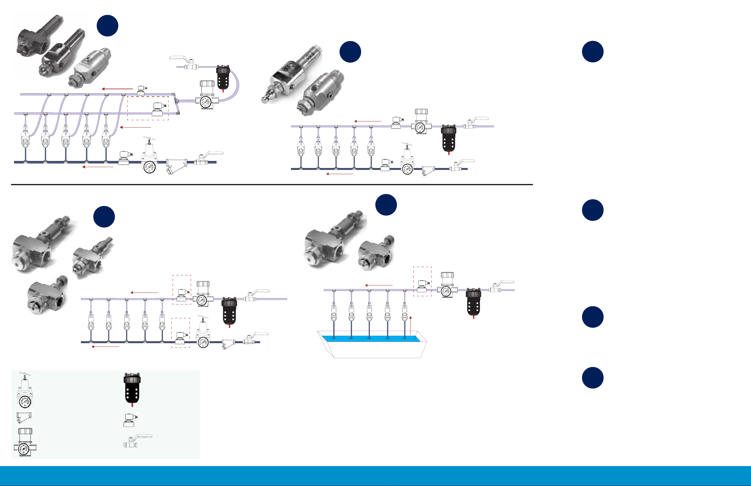
For Systems AA and BB
Liquid ow is shut off
in the nozzle with a
poppet valve operated
by an air cylinder
controlled by a 3-way
solenoid valve. The
00, 02, and 10 bodies
respond faster than the
01 and 11 bodies.
If you need assistance designing your XA system, please email or fax your
or 413-772-6729.
02 and 10 Bodies
Use a 3-way valve on the cylinder air line for
the fastest response. Use an optional 2-way
solenoid valve on the atomizing air line to
conserve air when the liquid ow is shut off.
Note that the atomizing air valve must open
before the 3-way cylinder air valve.
00 Body
The operation is the same as for the 02
body, but the piping is more difcult
because the location of the cylinder air
inlet is independent of the atomizing air
inlet. Flexible tubing may be used for some
applications.
An additional regulator is required for either
the 02 or 00 body if the atomizing air is to be
less than 30 psi.
AA
01 and 11 Bodies
Because this body has a single inlet for
cylinder and atomizing air, it requires only
one 3-way solenoid valve for control. The
response of the 01 body is slower than for
the 02 and 00 bodies because the liquid ow
doesn’t stop until the air has drained from the
line.
Atomizing air pressure must be greater than
30 psi to provide adequate cylinder pressure.
BB
00 Body
Liquid is fed under pressure to the 00 body,
which uses A, B, C or D hardware. Note that
systems similar to CC can be designed using
the 03, 05, 06, 07, and 08 bodies.
CC
00 Body
SR or SF set-ups siphon liquid from a
container to the
00 body, which uses A, B, C or D hardware.
Note that sytems similar to DD can be
designed using the 03, 05, and 07 bodies.
DD
LEGEND
Water Pressure Regulator Air Filter
Solenoid Valve
Manual Ball Valve
Water Strainer
Air Pressure Regulator
80
60
40
20
0
100
120
140
160
psi
80
60
40
20
0
100
120
140
160
psi
Cylinder Air Line
Atomizing Air Line
Liquid Line
3-Way Solenoid
Valve
2-Way Solenoid
Valve
OPTIONAL
Fastest Response - No Drips or Sputtering After Shutoff
00, 02 or 10 Body - E or F Hardware
Liquid Fed Under Pressure
80
60
40
20
0
100
120
140
160
psi
80
60
40
20
0
100
120
140
160
psi
Atomizing and
Cylinder Air Line
Liquid Line
3-Way
Solenoid
Fastest Response - No Drips or Sputtering
After Shutoff, Simplied Piping
01 or 11 Body - E or F Hardware
Liquid Fed Under Pressure
80
60
40
20
0
100
120
140
160
psi
80
60
40
20
0
100
120
140
160
psi
Atomizing Air Line
Liquid Line, Pressure Feed
2-Way
Solenoid
OPTIONAL
2-Way
Solenoid
OPTIONAL
Slow Response - Some Drips or Sputtering After Shutoff,
Simple Piping
00 Body - A, B, C or D Hardware
Liquid Fed Under Pressure
80
60
40
20
0
100
120
140
160
psi
Atomizing Air Line
Siphon Feed
Liquid Lines
Liquid Reservoir
2-Way
Solenoid
OPTIONAL
Slow Response - Some Drips or Sputtering
After Shutoff, Simple Piping
00 Body - A, B, C or D Hardware
Liquid Siphoned from Container
XA SYSTEMS
AA
BB
CC
DD
For Systems CC and DD
Using 00, 03, or 05
bodies, manual ball
valves or electric
solenoid valves control
the uid ow.

Visit BETE.com for comprehensive spray nozzle tools, case studies and literature.
WHAT YOU NEED TO
CONSIDER WHEN
DESIGNING YOUR XA
SYSTEM
FILTERS,
REGULATORS &
VALVES
WATER AND AIR FLOW DATA
• Conrm that the correct nozzle ow rate,
spray pattern, and operating pressures
have been selected and supplied for the
application, that the correct mounting
and accessory hardware such as thick
wall adapters and clean out needles
are installed on the nozzle and that the
correct number of nozzles is available.
• The header (for a multiple nozzle
installation) and supply lines should be
sized generously to prevent imbalance
between liquid and air pressures for each
nozzle and excessive pressure losses
along the header that could cause erratic
nozzle operation.
• Size the header to accommodate the total
ow to all the nozzles on the header.
Headers that are longer than 10 feet or
that have more than 10 nozzles may be
fed from both ends to minimize pressure
differences along their length.
• Be sure to account for the air pressure
according to the instructions on the chart
when sizing the air piping.
• The line supplying air to an automatic
cylinder can usually be 1/8” even when
multiple nozzles are used since the
volume ow of air to the cylinders is
very small.
• When the nozzles are supported by at
least one rigid pipe or wall, plastic tubing
often makes connections fast and easy,
but be certain the inside diameters of the
tubing to be used are as large as those in
the corresponding pipe size.
• Filters for the air and water lines should
be placed upstream of pressure regulators
and solenoid valves. Regulators and
pressure gauges should be placed as close
to the nozzles or header inlet as possible
to allow the regulator to respond rapidly
to pressure changes, especially when
the nozzles are being cycled on and off
automatically.
• Solenoid valves are generally installed
downstream of the pressure regulator
and as close to the nozzle as possible,
especially if they are to be used to cycle
the nozzles on and off.
• Automatic operation requires at least one
three-way valve so that air can escape
from the cylinder and allow the spring
to push the clean-out or clean-out/shut-
To determine the cubic feet per minute of
compressed air at any temperature and
pressure other than standard conditions, use
the equation:
(14.7 / p + 14.7) (460 + T / 520) (SCFM) = ACFM
Therefore, to determine the pressure drop for
inlet or average pressure other than 100 psi and
at temperatures other than 60°F, multiply the
values given in the table by the ratio:
(100 + 14.7 / P + 14.7) (460 + T / 520)
Where:
“P” is the inlet or average gauge pressure
in pounds per square inch, and, T is the
temperature in degrees Fahrenheit under
consideration.
Example: Suppose you need to supply two
XAPR300 nozzles with 60 psi water and 50 psi
air as shown in the diagram below.
Water
Total ow = (59 gph) x 2 / 60 = 1.96
gpm
Select 3/8” or larger pipe
Air
Total Flow = (4.6) x 2 = 9.2 scfm
Note that tabulated pressure losses will need to
be multiplied by
(100 + 14.7 / P + 14.7) = (114.7 / 50 + 14.7) = 1.77
to obtain losses at 50 psi. Select 3/8” or larger
pipe.
BETE recommends that lters be used on both
the air and liquid lines supplying XA nozzles
to minimize the potential for clogging. The air
lters supplied by BETE remove both water
and particulates and are equipped with an
automatic drain. The water lters remove
particulates larger than 100 mesh and can
be equipped with a quick ush drain valve to
remove accumulated deposits.
Liquid strainers for siphon setups should have
large areas to minimize pressure losses across
the strainer itself. It is also preferable to install
the strainer below the liquid level.
The standard liquid pressure regulators
supplied by BETE are the unbalanced type and
the downstream pressure may uctuate with
variations in inlet pressure regardless of the
pressure setting. The air regulators are the
relieving type and pressures can be set without
the air actually owing through the nozzles. In
addition these are less sensitive to variations in
upstream pressure.
If you have further questions, please do
not hesitate to call our customer service
department at 413-772-0846 or visit our website
at: www.bete.com.
off needle into place. Faster operation is
usually possible when you control the
cylinder separately using the 00, 02, or 03
body. Using the 01 body requires the air to
be exhausted from the larger atomizing
air supply piping to allow the cylinder to
return to the closed position.
• A complete XA system diagram with
lters, regulators and solenoid valves
is shown to the right and in the XA
Accessories brochure.
• You must correctly size the supply piping
to ensure that adequate air and water
are supplied to the nozzle. Correct size
is especially important in multi-nozzle
systems where differences in air and
water pressures from one nozzle to the
next can cause erratic operation.
• Several charts are included to help you
choose the correct pipe sizes.
Flow of air through schedule 40 steel pipe
For lengths of pipe other than 100 feet, the
pressure drop is proportional to the length.
Thus, for 50 feet of pipe, the pressure drop is
one-half the value given in the table; for 300
feet, three times the given value, etc.
The cubic feet per minute of compressed air at
any pressure is inversely proportional to the
absolute pressure and directly proportional to
the absolute temperature.
The pressure drop is also inversely proportional
to the absolute pressure and directly
proportional to the absolute temperature. .
Siphon System
Pressure System with XA02 Body


