Betec BJ-05 User manual

These operating instructions are designed to explain to the user how this
device works.
Please read these instructions through carefully before using the device, to
ensure that you are familiar with all functions and how to operate the
device.
Congratulations on your purchase of this device from the floor standing
series of intelligent banknote counters. We welcome feedback from our
users to allow us to continually improve our products.
OPERATING INSTRUCTIONS
BANKNOTE COUNTER
BJ-05
-BJ05_Anleitung engl. 01.11.2006 8:30 Uhr Seite 1

INTRODUCTION
The portable floor standing appliances from the series of intelligent banknote counters
have been fitted with a series of intelligent functions by our development team. The use of
a precision portable device in retail and in banking saves time and effort and prevents
errors.
The intelligent banknote counting machines are available in the following three designs:
• The Basic version. This has the following functions: Counting, adding, stacking, detecting
damaged or connected banknotes, detecting double banknotes and format (width).
• The UV model has all the functions featured in the basic version and is also fitted with a
UV detector to detect counterfeit banknotes.
• The UV/MG model l again has all the functions of the basic model, along with UV and
magnet testing to detect counterfeit banknotes.
Please note: The double note detection feature and magnet testing are optional and
can be provided on request.
-BJ05_Anleitung engl. 01.11.2006 8:30 Uhr Seite 2
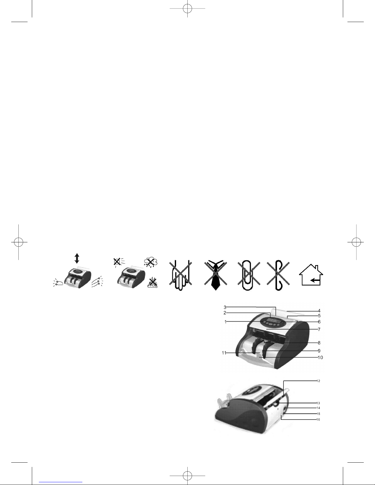
1.0 Important safety information
• The device must be operated with a circuit breaker plug, if fluctuations in the voltage of
over 10% are expected, in order to avoid errors.
• The fuse is 1.5 A at 220 V and 2 A at 110 V. These values may not be exceeded.
• The device must not be operated if the cover is open.
• The device has a time delay of 3 seconds for the renewed activation of the "ON/OFF"
switch to increase the life of the display.
• Ensure that the sensors and the UV detector cannot be moved.
• The defined paper strength must not be exceeded. Do not insert any objects into the
device.
• Avoid contact with fingers, ties, hair, paperclips or nails to the banknote feed wheel.
• The device must be kept out of reach of children; it may only be operated by adults. Take
care when transporting the device.
• It is not recommended to use the device in high temperatures or direct sunlight.
• Unplug the device if it is not to be used for longer periods.
3
2.0 Description
1) PVC operating field
2) Display for counting display
3) Sensor banknote feed
4) Banknote feed
5) Foldable handle for carrying
6) Display for stacks (10, 20, 25, 50, 100)
7) Top cover
8) Counting sensor
9) Transport wheels
10) Stacking tray
11) Sensor output tray
12) Rubber resistance disc
13) Adjustment of paper strength for banknote feed
14) Mains plug
15) Mains cable
16) Connection for external display (optional)
Fig. 1
Fig. 2
-BJ05_Anleitung engl. 01.11.2006 8:30 Uhr Seite 3
3.0 Technical specifications
1) Ambient temperature: 0~40° C
2) Ambient humidity: 30~80%
3) Feed mechanism: roller single note feed
4) Counting speed: > 900 banknotes/min.
5) Admissible banknote dimensions: 115 x50 ~ 167 x 85 mm
6) Admissible banknote thickness: 0.075 ~ 0.15 mm
7) Banknote feed with output tray: 100 banknotes (old notes)
200 banknotes (new notes)
8) Counting display: three digit LED
External display: four digit LED
9) Display for selecting stack size: three digit LED
10) Power supply: 220 V AC (±10%), 50 Hz or
110 V AC (±10%), 60 Hz
11) Power input: < 65 W
12) Power input in stand-by mode: < 10 W
13) Dimensions (H x W x D): 155 x 244 x 270 cm/mm
14) Dimensions of packaging (H x W x D): 200 x 290 x 330 cm/mm per device
15) Net and gross weight: approx. 4.50 kg and 5.00 kg per device
4.0 Essential features
Auto-test function, stop if damaged banknotes are detected (combined, half or double ban-
knotes), counting feature, testing feature, counting with addition, stacking mode with pre-
selection, auto-start and automatic cleaning.
Please note:
• Prior to use, check the voltage and ensure that this corresponds to the voltage requi-
rements of the device. Use a suitable mains cable.
• Operating the buttons of the operating field in stand-by mode does not cause errors.
• In the event of an error in the feed or a jam caused by faulty operation the device must
be switched off immediately as it can otherwise be damaged.
• To allow counterfeit notes to be detected properly, the following banknotes should be
sorted:
– banknotes that are stuck together
– banknotes that have been washed
– heavily soiled banknotes
– damaged banknotes
4
-BJ05_Anleitung engl. 01.11.2006 8:30 Uhr Seite 4
5.0 OPERATING
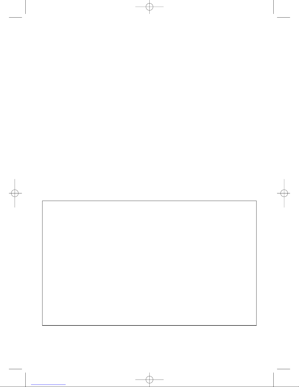
5.1 Banknote feed
This is at the back of the device. To avoid errors, the banknotes need to be fed in properly.
Please observe the following:
• Ensure that there are no items on or between the banknotes, such as scraps of paper,
paper clips, rubber bands, baneroles, etc (see fig. A).
Damaged or soiled banknotes must be sorted prior to the counting process (see fig. B).
Smooth out creased or folded banknotes prior to the counting process (see figs. Cand D).
5
Scrap of paper
Paper clip
Rubber band Damp and/or soiled
banknotes
Stack of banknotes with paper clips, scraps of paper or rubber band
Creased banknotes Folded banknotes
• Stack the pile of banknotes from behind. This
loosens new banknotes and ensures that they
do not stick together. Insert the banknotes so
that those at the top are fed into the device
first (see fig. 3).
• To achieve this, the back of the stack of
banknotes must be at right angles to the
banknote feed shaft. Then lightly push the
banknotes back, so that they fan out at the
back. The top banknote is then fed into the
device first (see fig. 4)
Fig. 3
Fig. 6Fig. 5
Fig. 4
• Figs. 5 and 6 show examples of incorrectly inserted banknotes; this can lead to the banknotes
not being fed in straight or can cause a jam.
-BJ05_Anleitung engl. 01.11.2006 8:30 Uhr Seite 5
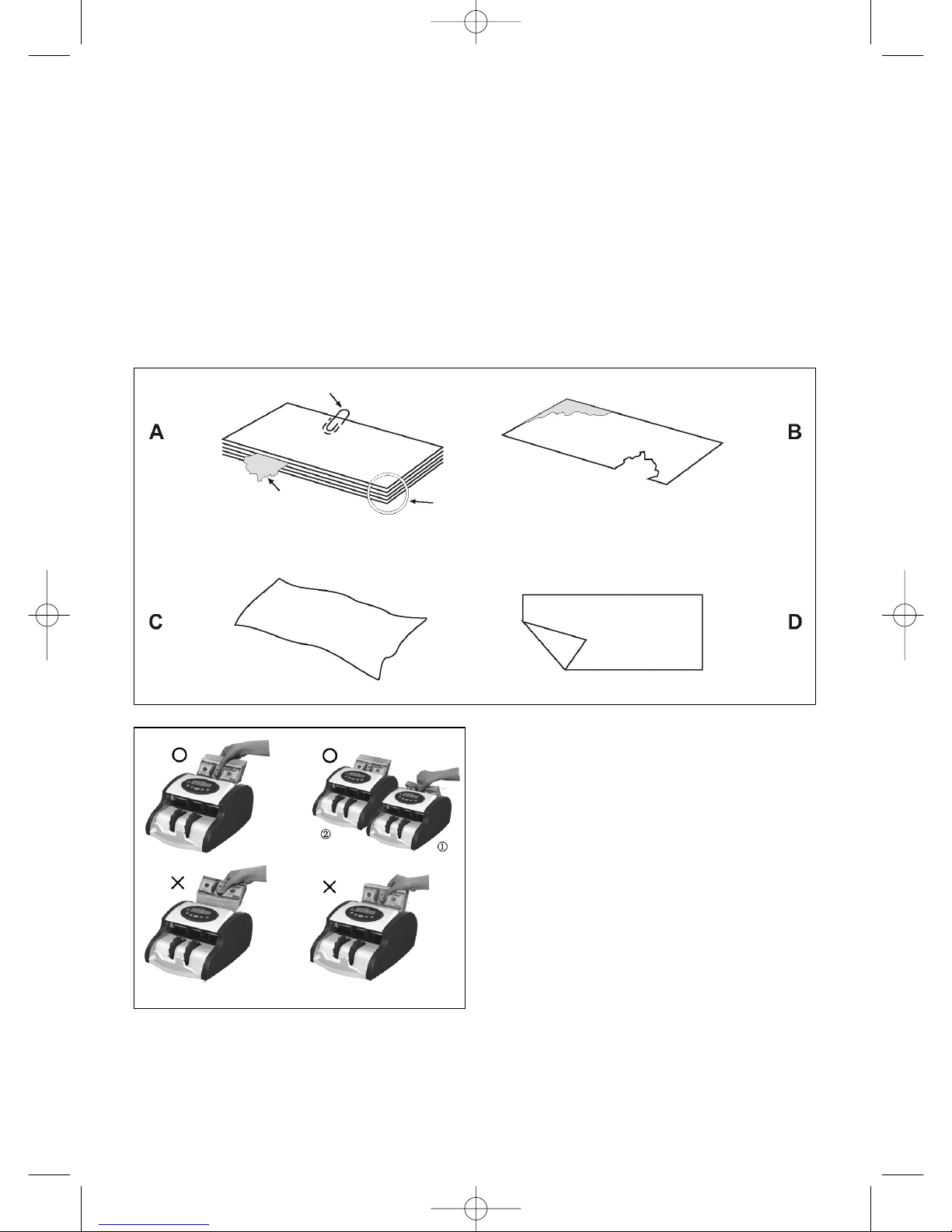
5.2 Auto-test feature
When the device is switched on via the
mains switch (888888)appears on the
counting and stacking display. This shows
that the device is testing all sensors (see
fig. E). "0" (see fig. F) displays that the
device is operational. In the event of an
error, an error code appears on the display
for counted banknotes (see fig. G). Please
refer to "7.1 Troubleshooting" for infor-
mation on rectifying errors and faults.
6
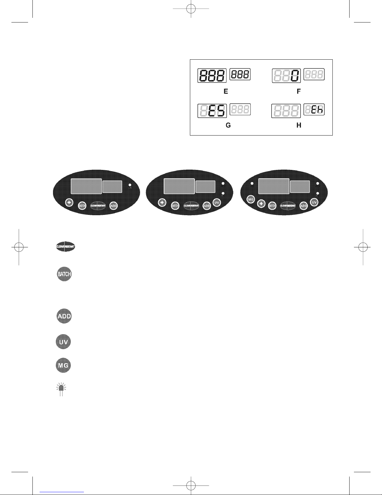
• This button is used to start the device. It is also used to reset the counter.
• The "BATCH" button is used to determine the size of the stack. Press this button
several times to select stack sizes of either 10, 20, 25, 50 and "unlimited".
Pressing the "PLUS" button adds one onto the number on the display. Pressing
the button quickly adds one onto the counter every quarter of a second. Stack
sizes can be freely selected from 1 to 99.
• The counter can be set up to "999" by pressing this button. It then returns to "0".
• To switch on the UV testing for all types of banknotes (for the UV and UV/MG
models).
• To switch on the testing feature for banknotes with magnetic ink (MG or UV/MG
models) (optional)
• This function display shows if the selected function is activated.
5.3 Button functions
Fig. 7-1 (basic model) fig. 7-2 (UV model) fig. 7-3 (UV/MG model)
Please note:
As the distribution and quantity of magnetic ink varies in banknotes, the magnetic test is
offered as an optional security test and should be used as specified by the customer or the
issuing authorities.
Do not use the nib of a pen or pointed items to press the buttons.
-BJ05_Anleitung engl. 01.11.2006 8:30 Uhr Seite 6

7
5.4 Counting feature
If a damaged banknote is detected during the counting process (a half, connected or double bankno-
te) or if an error occurs, the device interrupts the counting process and the error code EC, Eh or Ed
appears in the stack display (see fig. H).
The back banknote in the output tray is the suspicious banknote. This banknote Is not taken into
account in the counting process.
5.4.1 Counting feature
This function is always carried out automatically, even if other function buttons have not been selected.
• When the banknotes are placed in the feed, the device automatically starts the counting process and
shows the value in the display.
• To count more banknotes, the banknotes initially counted have to be removed from the output tray
and the next stack has to be placed into the feed. The device displays the quantity as "0" and
restarts the counting process.
• If the banknotes remain in the output tray and new banknotes are placed in the feed, the device
automatically continues the counting process and adds the new stack onto the stack that has alrea-
dy been counted.
• If a banknote suspected to be counterfeit (half, connected or double banknotes) is detected, the
device automatically stops the counting process and an alarm sounds briefly. The error code EC, Eh
or Ed see fig. H) flashes on the display. In this case all banknotes have to be removed from the output
tray and then placed back into the feed to allow the counting process to restart. The counter must
first be set to "0" by pressing the "RESTART/CLEAR" button.
5.4.2 Counterfeit note detection (for UV/MG model)
There are functions for UV testing, magnetic testing, detecting banknotes that are stuck together and
double notes.
• Select the test functions you would like to carry out for the banknotes.
• If a suspicious banknote is found by UV testing, the device interrupts the process and the error code
"CF1" appears on the display.
• If the device detects a banknote without a magnetic line or with the ink in the wrong place, a war-
ning signal sounds and the error code "CF2" appears on the display.
• For testing connected banknotes, the device detects banknotes with a width of more than a third of
the length.
• The test function for half banknotes detects banknotes shorter than 70 mm.
• For double note detection, the device filters all banknotes with a thickness of 0.16 mm thicker than
original banknote or with a thickness of more than two banknotes.
• The first banknote fed into the device provides the control value for the thickness, allowing the devi-
ce to automatically detect if the thickness is 3 mm ~ 5 mm more than the first banknote (optional
function).
• If the device stops because of an error (in the UV, MG or size testing), the banknotes that have alrea-
dy been counted must be taken out of the output tray to allow the counting and testing process to
restart.
Please note: As the UV testing can differ depending on which side of the banknote that is tested, this
test should be repeated on the back of the banknote to increase the accuracy of the test. This device
should not be exposed to direct sunlight, as this can lead to errors in the UV testing and inaccurate
counting results. The proximity of the device to magnetic fields can also lead to inaccurate results.
-BJ05_Anleitung engl. 01.11.2006 8:30 Uhr Seite 7

8
5.4.3 Counting with additionn
• Pressing the "AD" button activates the addition mode. The corresponding symbol
appears on the display.
• Place the banknotes into the feed. The device automatically starts to count them. The
result is displayed in the counter display.
• The device continues the counting process if new notes are placed in the feed, even if
the banknotes are removed from the output tray. If more than 999 notes are counted, at
1000 notes the display returns to "0" and the counting process is continued.
• If stack counting is also activated with the addition option and the counting process is
interrupted on account of a faulty note (half, connected or double notes), the error code
Ec, Eh or Ed appears on the stack display.
• In this case the counted banknotes have to be removed from the output tray. The coun-
ting process is continued when the "RESTART" button is pressed.
The counting process is then continued starting at the last stack without an error - only the
stack with an error has to be recounted. This means that the faulty stack is not included in
the final counting. The quantity is only updated for a new stack.
5.4.4 Stack counting with pre-setting
• The "BATCH" button is used to determine the size of the stack. Press this button several
times to select stack sizes of either 10, 20, 25, 50 and "unlimited". Pressing the "PLUS"
button adds one onto the number on the display. Pressing the button quickly adds one
onto the counter every quarter of a second.
The function is deactivated by pressing the "BATCH" button again.
• When the banknotes are placed in the banknote feed, the counting process automatically
starts. When the selected number is reached, the device automatically stops. The
quantity displayed in the counter display is reset when the counted banknotes are remo-
ved from the output tray, even if further banknotes remain in the feed.
• There are two options to continue the stack counting process. The first method is to
remove the counted banknotes from the output tray. The second method is to press the
"RESTART" button after each stacking process without removing the banknotes that
have already been counted. The device then continues the stack counting process.
• If there are no notes in the feed and the set stack size has not yet been reached, the
quantity flashes on the display until the user places more banknotes into the feed. The
device then counts the extra notes until it reaches the selected number.
• If the stack size varies from one counting process to another, a stack size has to be
selected and the counted notes from one counting process have to be removed from the
output tray. A new stack size can then be selected.
-BJ05_Anleitung engl. 01.11.2006 8:30 Uhr Seite 8
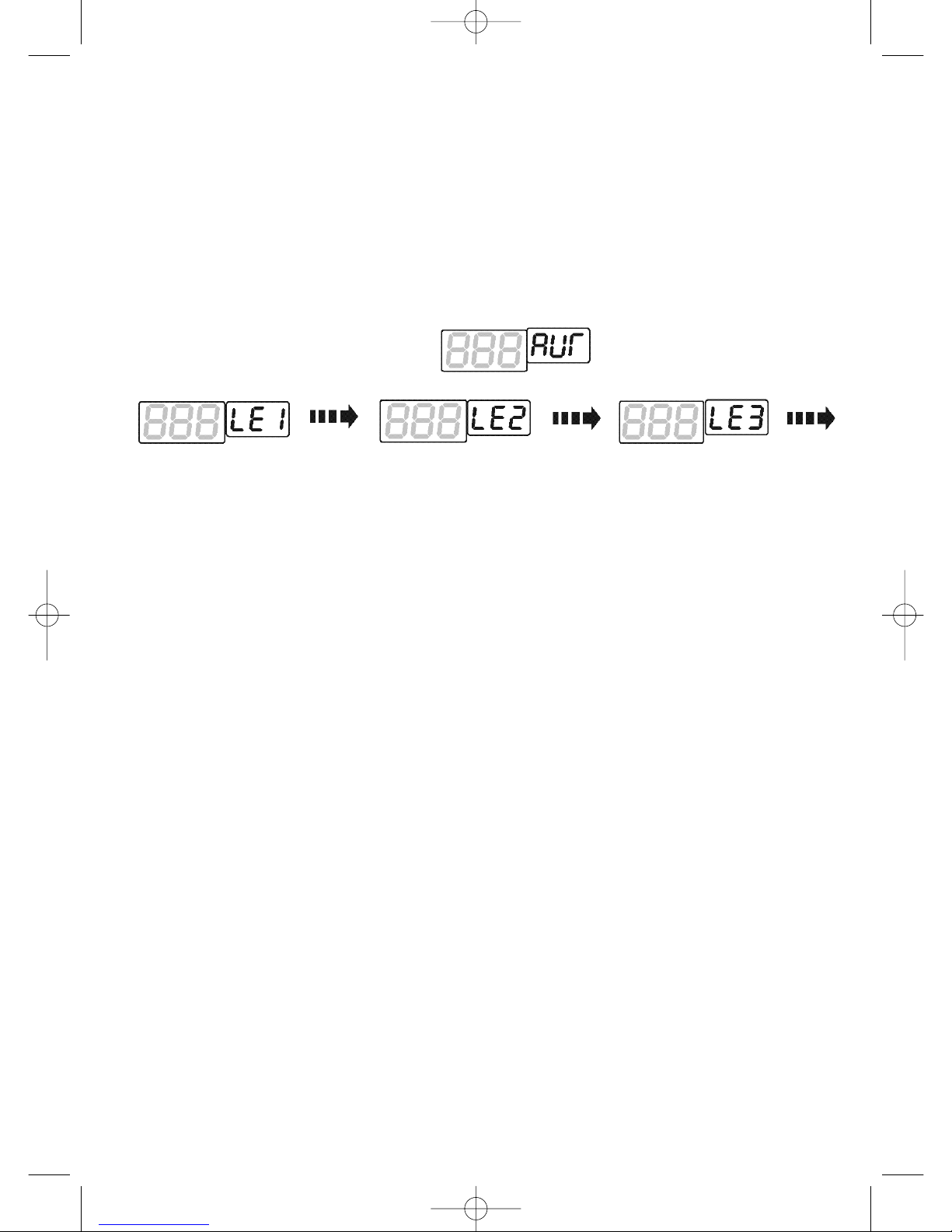
5.5.2 Setting the sensitivity for the magnet testing (for the UV/MG model)
If the "MG" button is pressed once, the value "MG1" appears on the stack display (see fig.
9). "MG" stands for magnet testing and "1" refers to the lowest testing sensitivity. To
increase the testing sensitivity, press the "MG" button again. "MG 2" then appears on the
stack display (greater sensitivity). The devices saves this setting after 1.5 seconds and
switches to stand-by mode.
5.5.3 Setting the width detection (optional)
If the "SIZE" button is pressed once, the value "5, 3" appears in the stack display (see fig.
10). The value "5" shows that the width detection has been activated and "3" shows the
setting for the greatest sensitivity, i.e. a measuring setting of 4 mm.
To switch to medium sensitivity "4", press the "SIZE" button again. The medium setting "5"
represents a measuring value of 5 mm or more.
The lowest sensitivity level "4" represents a measuring setting of 6 mm or more. The device
saves this setting after 1.5 seconds and switches to stand-by mode.
9
Fig. 8
Fig. 9
Fig. 10
5.5 Setting the sensitivity for detecting counterfeit notes
Please note: The sensitivity setting may not be carried out when the device is
operational.
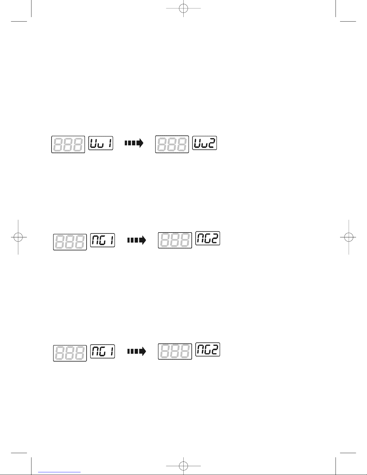
5.5.1 Setting the sensitivity for the UV testing
If the "UV" button is pressed once, the value "UV1" appears on the stack display (see fig.
8). "UV" stands for UV testing and "1" represents the testing sensitivity. If the testing is to
be more sensitive, press the "UV" button again. "UV2" then appears on the stack display
(greater sensitivity). The device saves this setting after 1.5 seconds and switches to stand-
by mode.
-BJ05_Anleitung engl. 01.11.2006 8:30 Uhr Seite 9
10
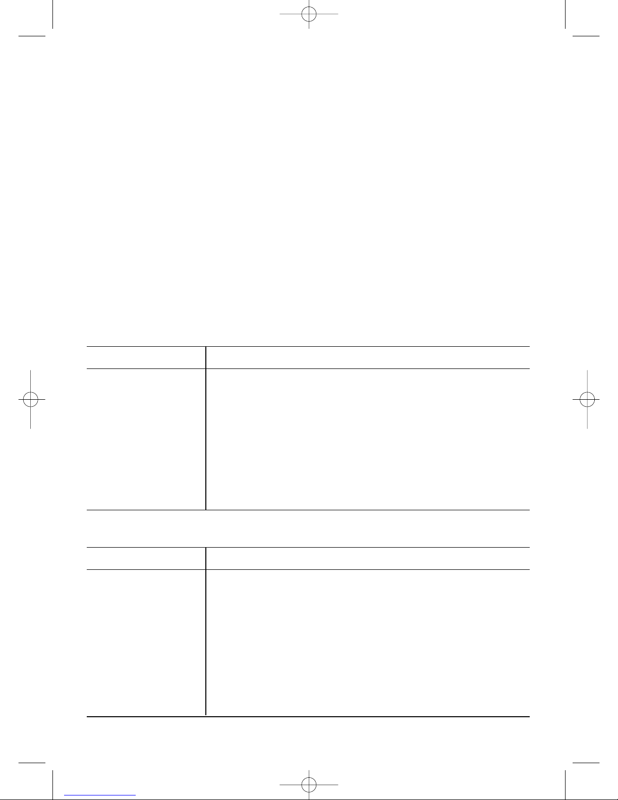
5.5.4 Setting the individual width detection (optional)
If the "LEVEL" button is pressed once, the value "AUF" appears in the stack display (see
fig. 11).
The device now individually detects the width of the notes. The width of the first banknote
acts as the control value. The sensitivity can be set by pressing the "LEVEL" button. If
pressed once, the value "LE1" appears on the display (see fig. 12). "LE" in this case
represents the width. "1" is the lowest value. More sensitive settings can also be selected
- "LE2", "LE3" and "LE4".
The device saves this setting after 1.5 seconds and switches to stand-by mode.
Fig. 12
Fig. 12
5.6 External display (optional)
• Connect the external display via the connection on the device.
• The external display shows the same value as the counter on the device.
6.0 SETTINGS
6.1 Setting the banknote feed
• The feed needs to be removed to allow adjustments to be made. First release the retai-
ning screw on the back cover. Carefully open the cover and release the retaining screw
of the banknote feed. Turn the adjustment screw of the feed anticlockwise. Carefully pull
the banknote feed back.
COMMENT:
Only pull the banknote feed out a little so that the sensor cable below the feed board
is not pulled out.
• The two springs on either side of the front of the feed can now be released. The banknote
feed cannot be freely moved.
• By turning the feed adjustment clockwise the gap between the banknote feed wheel and
the rubber resistance disc is increased and the resistance thereby reduced. Turning the
adjustment screw anticlockwise allows the gap to be reduced again.
-BJ05_Anleitung engl. 01.11.2006 8:30 Uhr Seite 10
6.2 Setting the rubber resistance disc
• Sollten im Laufe der Zeit Ungenauigkeiten bei der Zählung entstehen oder Banknoten •
If, over time, there are inaccuracies in counting or banknotes are no longer easily fed into
the device, this could possibly be due to wear of the resistance disc. It then either needs
to be adjusted or replaced.
• If the resistance disc shows signs of wear, turn the adjustment screw anticlockwise and
carefully lift the banknote feed. A distance of approximately 0.5 mm is required between
the banknote feed wheel and the resistance disc to ensure the necessary friction for the
banknote feed.
Please note: If there are errors in the counting process it is recommended that you turn the
adjustment screw one or two rotations while the device is operational.
• If the rubber of the resistance disc shows signs of severe wear, press the disc with your
thumb and remove it. Turn the disc around or replace it.
• The resistance disc then needs to be replaced in its original position. Observe the exact
position of the left and the right side.
• After replacing the disc, switch the device back on and place a banknote in the feed. If
the disc has been positioned correctly the banknote will be fed in properly.
11
Cause
The left counter sensor is dusty or damaged.
The right counter sensor is dusty or dama-
ged.
Severe fault of the magnet function or faulty
circuit.
Damaged UV sensor or circuit.
The sensor of the banknote feed is dusty or
damaged.
The sensor on the output tray is dusty, not
centrally aligned or is damaged.
Remedy
Clean or exchange the sensor
Clean or exchange the sensor
Clean the magnet head or wheel or
repair the circuit
Exchange the sensor or repair the
circuit
Clean or exchange the sensor
Clean, adjust or exchange the sensor
Error code
E1
E2
E3
E4
E5
E6
7.0 Trouble shooting
Cause
UV testing or device stop for detecting counterfeit notes
(for UV and UV/MG models)
Magnet testing or device stop for detecting counterfeit notes (for
MG and UV/MG models)
Width detection below level 3 or over 5 mm and device stop
(optional function)
Detection of connected banknote and device stop
Detection of half banknote and device stop
Double banknote detection and device stop (optional function)
Error code
CF 1
CF 2
dd
EC
Eh
Ed
7.1 Error messages
-BJ05_Anleitung engl. 01.11.2006 8:30 Uhr Seite 11
8.0 Care and maintenance
• It is essential to switch off the device and to disconnect the mains cable prior to cleaning.
• Clean all optical sensors on the device once a day with a brush or a soft cloth to prevent
any dust particles or paper pieces sticking to them. Then cover the device with a dust
cover or a cloth.
• All sensors (e.g. the sensors of the banknote feed, counter and output tray) should always
be cleaned with a brush or a soft cloth to ensure smooth operation.
• The inside of the device should be regularly cleaned with a soft brush or cleaner.
• The magnet sensor, UV light and UV detector should be cleaned with alcohol, water
(magnet head) and a soft cloth to ensure good detection performance.
Please note:
• If there is a problem with the device that you cannot rectify, please contact your supplier
or its customer service department.
• This device has been precision designed and thoroughly tested by our engineers. Errors
can, however, occur. Under certain circumstances original banknotes may be identified
as counterfeit. In this event, the counting process needs to be restarted.
9.0 SCOPE OF DELIVERY AND ACCESSORIES
9.1 The following are supplied with the device
• Operating instructions 1 copy
• 1 cleaning brush
9.2 Accessories
• 1 fuse (Ø 5x18)
• 1 set of banknote wheels (4 items)
• 1 drive belt
• 1 rubber resistance disc
• 1 external display (optional)
12
Part-No. 3820
BETEC · Herzogstr. 55 · D-63263 Neu-Isenburg
Phone +49 (0) 61 02 / 310 67 · Fax +49 (0) 61 02 / 32 08 59
© BETEC
MADE IN
CHINA
-BJ05_Anleitung engl. 01.11.2006 8:30 Uhr Seite 12
Table of contents
Other Betec Banknote Counter manuals


