BETTENERGY Powerbox4400LV User manual

POWERBOX
1
User Manual
Model: Powerbox4400LV/6100LV

POWERBOX
2
Index
1 GENERAL Information..................................................................................................3
1.1 Validity .............................................................................................................3
1.2 Intended Use.....................................................................................................3
1.3 Product Identification.......................................................................................4
2Safety Measures..........................................................................................................5
3Technical Parameters ..................................................................................................6
4 Technical Items ...............................................................................................................8
5 Product Overview ...........................................................................................................9
5.1 Brief Introduction.................................................................................................9
5.2 Interface Introduction...........................................................................................9
5.2.1 Start Button.............................................................................................10
5.2.2 LED Indicators Definition ......................................................................10
5.2.3 Dial-up Switch Definition.......................................................................13
5.2.4 The CAN port .........................................................................................14
5.2.5 The RS232 Port.......................................................................................15
5.2.6 RS485-1 ..................................................................................................15
5.2.7 RS485-2 ..................................................................................................16
6 The Installation Guide...................................................................................................17
6.1 Checking before Installation..............................................................................17
6.1.1 Check the packing...................................................................................17
6.1.2 Check the Deliverables...........................................................................17
6.2 Tools...................................................................................................................20
6.3 Installation Requirements ..................................................................................21
6.3.1 Installation environment requirements ...................................................21
6.3.2 Installation Carrier requirements ............................................................21
6.4 Installation Instructions......................................................................................22
6.4.1 Overall Dimensions ................................................................................22
7 Cleaning and Maintenance............................................................................................30
7.1 Cleaning.............................................................................................................30
7.2 Maintenance.......................................................................................................30
7.2.1 Recharge Requirements during Normal Storage ....................................30
7.2.2 Recharging requirements for excessive discharge..................................31
8 Common Issues and Solutions......................................................................................32
8.1 Common Issues and Solutions...........................................................................32
8.2 Emergency .........................................................................................................33
8.3 Handling of the battery system..........................................................................33

POWERBOX
3
1 GENERAL Information
This manual introduces the BETTENERGY POWERBOX-4400LV/6100LV battery
products. Please read this manual carefully before using the battery. For any questions,
please contact the BETTENERGY / SEEKENER immediately for advice and
clarification.
1.1 Validity
This user manual is applicable to BETTENERGY POWERBOX-4400LV/6100LV,
This manual contains BETTENERGY POWERBOX-4400LV/6100LV information,
usage, guidance, safety information, installation guide and details on common operation
issues and subsequent maintenance measures.
1.2 Intended Use
BETTENERGY POWERBOX is an energy storage unit that is designed for
residential application scenarios with the capability of short-term backup.
Notes:
BETTENERGY POWERBOX-4400LV/6100LV is not suitable for supporting
life-sustaining medical devices. This product is intended for used only in accordance
with the information provided in the enclosed documents and applicable local standards
and regulations. Any other use may result in personal injury or property damage. The
illustrations in this manual are only intended to help explain the concept of the system
configuration, including use guidelines, safety precautions, common operating problems,
and subsequent battery maintenance.
Alterations to the product, e.g. changes or modifications, are only permitted with the
express written permission of SEEKENER. Unauthorized changes will not be allowed
by warranty claims. SEEKENER shall not be liable for any damage resulting from
such changes. Any use of the product other than described in the intended use section does
not qualify as appropriate. The enclosed documentation is an integral part of this product.
Please keep the documentation in a safe and convenient place for future reference.
Product model labels (see Section 1.3) must be attached to the product.

POWERBOX
4
1.3 Product Identification
The type labels were attached on the product,which contain the product identification
information. For safe usage, the user must be well-informed of the contents in the type
labels.
The Labels include:

POWERBOX
5
2Safety Measures
This section contains safety information that must always be observed when using or
installing batteries. To prevent personal injury or property damage and ensure long-term
operation of the batteries.
Environmental requirements:
1. Do not expose the battery to temperature above 50 °C;
2. Do not place the battery near any heat source;
3. Do not expose the battery to moisture or liquid;
4. Do not expose the battery to a corrosive gas or liquid;
5. Do not expose the battery to a combustible gas or liquid;
6. Do not expose the battery to direct sunlight for extended periods of time;
7. Battery power terminals are not allowed to contact conductive objects, such as electric
wires;
8. Place the battery in safe place that away from children and animals;
Operation Precautions:
1. Do not disassemble the battery;
2. Do not touch the battery pack with wet hands;
3. Do not smash, fall, or puncture the battery;
4. Do not reverse the polar series connection battery;
5. Do not short-circuit the terminal, and remove all metal jewelry items that may
produce a short-circuit before installation and repair;
6. Always handle the products in accordance with the local safety regulations;
7. Store and use the battery in the user's manual;
8. Ensure reliable grounding;
9. Disconnecting all batteries to the wires before installation and repair;
10. Do not stack batteries outside the protective packaging during storage or handling;
11. The stacking of packaging batteries shall not exceed the quantity specified on the
packaging;
12. Continued operation of a damaged battery may lead to dangerous situations, causing
serious injuries such as electric shock or combustion;

POWERBOX
6
3Technical Parameters
Basic Parameters
Technical Specification
Model
POWERBOX-4400LV
POWERBOX-6100LV
Battery Type
LiFePO4, Lithium iron
Phosphate
LiFePO4, Lithium iron
Phosphate
Nominal Capacity (Ah)
86A.h
120A.h
Nominal Voltage (V)
51.2V
51.2V
Total Energy
4400W.h
6100W.h
Depth of Discharge
(90%DOD)
3960W.h
5490W.h
Maximum Charging
Voltage (V)
56.8V
56.8V
End of Voltage (V)
49V
49V
Nominal charging current
(A)
40A
60A
Maximum Charging
Current (A)
50A
80A
Maximum Charging Power
(W)
2560W
4096W
Nominal Discharge
Current (A)
50A
60A
Nominal Discharge
Power
(W)
2560W
3072W
Maximum Discharge
current (A)
60A
80A
Maximum Discharge
Power (W)
3072W
4096W
Working Humidity
≤95%rh
Store humidity
≤95%rh

POWERBOX
7
Working Altitude
≤2000m
Maximum number of
parallel
A maximum of 16 units are recommended
Protection Level
IP20
Net Weight(KG)
46KG
60KG
Dimensions(mm)
434 * 145 * 450mm
434 * 183 * 450mm
Product Certificate
CE,ROHS,UN38.3,MSDS,IEC-62619
Circle Life
≥ 5,000 times, 80%DOD / 25℃/0.5C, 60%EOL
Communication Port
CAN,RS485,RS232
Operating temperature
-10℃ ~ 55°C
Storage temperature
≤ 25℃, 12 months;
≤ 35℃, 6 months;
≤ 45℃, 3 months;
Note: Operating current derating according to the cell voltage and temperature.

POWERBOX
8
4 Technical Items
No.
Name
Comment on this one
1
Discharge
Battery output power for load
2
Charge
Put the electricity in to the battery through the charger
3
Full Charge
The battery is fully charged with 100% SOC.
4
Standby
Ready for charging or discharging
5
Shutdown
Shutdown
6
SOC
State of Charging (Useable Capacity)
7
Battery voltage
Voltage between the battery B+ /B -
8
Single-string voltage
Single-cell voltage
9
Alarm
Indicates that the battery is in an abnormal state
10
Protection
The battery stops charging or discharging and is
recoverable
11
Fault
Battery or BMS is damaged and need to be replaced
12
Over discharged
Battery is lack of electricity, and need to be charged in time
POWERBOX
9
5 Product Overview
5.1 Brief Introduction
Product Overview: BETTENERGY POWERBOX-4400LV/6100LV is a Lithium
battery energy storage system with an operating voltage range of between 49V~56.8V, it is
used for household energy storage applications, in cooperation with low voltage inverters
to achieve home energy storage purpose.
The product has a built-in B M S (Battery Management System) which can manage
and monitor cells information, including voltage, current and the temperature. In
addition, the BMS can balances battery charging to extend lifespan. BMS has the
protections including over-discharge, overcharge, over-current, high / low temperature,
etc.
The system can automatically manage the charging state, discharge state and balance
state. Multiple batteries can be connected in parallel to expand storage capacity to meet
larger capacity and longer power supporting duration requirements, and the
BETTENERGY POWERBOX supports up to 16 parallel operation.
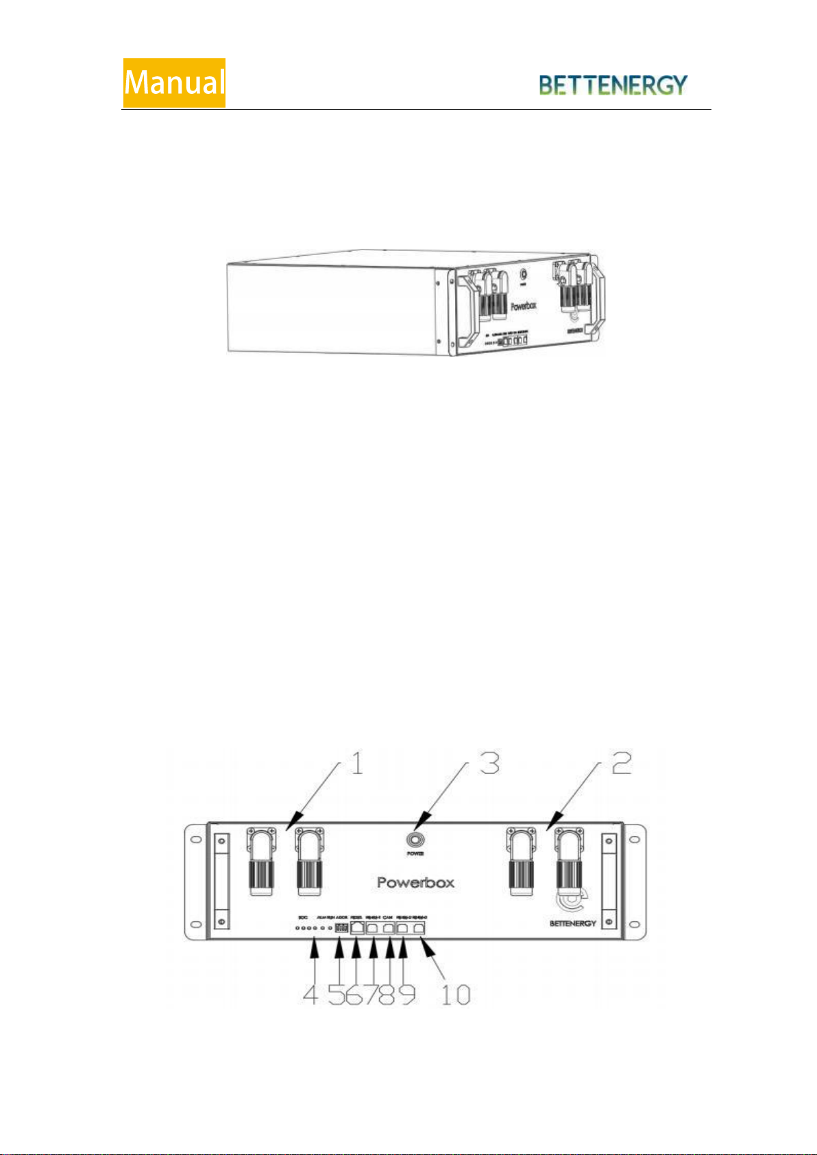
5.2 Interface Introduction

POWERBOX
10
No.
Items
No.
Items
1
Battery Module Positive Pole
6
RS232
2
Battery Module Negative Electrode
7
RS485-1
3
Start Button
8
CAN
4
The LED Indicator
9
RS485-2
5
RS485
10
RS485-2
5.2.1 Start Button
Press the start button, release the button, and the button is locked.
The SOC LED light starts from left to right, and the RUN light shows the operating status.
5.2.2 LED Indicators Definition
SOC lamp: 4 in total, indicating the battery power.
ALM lamp: Fault alarm lamp, faulty or protected.
RUN lamp: Operation status lamp

POWERBOX
11
Instructions for using the LED indicator lamp
LED Indicators Instructions
Status
Normal/
alarm and
protection
Runn
ing the
light
Alarm
Power level indicator lamp
Description
Green
In color
Red in
color
Green
L4
Green
L3
Green
L2
Green
L1
Shutdown
Off
Off
Off
Off
Off
Off
Off
All Off
Standby
Normal
Flash-1
Off
Display according to the power quantity
Standby
Alarm alarm
Flash-1
Flash 3
See the table below
Battery is at low voltage
Charge
Normal
Light
Turn-Off
See the table below
The alarm indicator is
turned off during the
overpressure
alarm
Alarm alarm
Light
Flash 3
Overcharge
protection
Light
Off
Open
Open
Open
Open
If no charger is connected
,the indicatpr light is
Consistent
with the standby shate
Temperatur
e, over
current
protection
Off
Light
Off
Off
Off
Off
Stop charging
Dischargi
ng
Normal
Flash 3
Off
See the table below
Alarm
alarm
Flash 3
Flash 3
Over-
discharge
Protection
Ion
Off
Off
Off
Off
Off
Off
Turn off the discharge

POWERBOX
12
Discharg
ing
Tempera
ture,
over-
current
short-
circuit
protect
ion
Off
Open
Off
Off
Off
Off
Turn off the
discharge
Failure
Off
Open
Off
Off
Off
Off
Turn off
the charge and
discharge
LED Flash Instructions:
Flash Mode
On
Off
Flash-1
0.25S
3.75S
Flash-2
0.5S
0.5S
Flash 3
0.5S
1.5S
Power Level Indication Description
Status
Charge
Discharge
Capacity
indicator lamp
L4
L3
L2
L1
L4
L3
L2
L1
Electricity
level(%)
1
~
25%
Out
Out
Out
Flash-2
Out
Out
Out
Bright
25~50%
Out
Out
Flash-2
Bright
Out
Out
Bright
Bright
50~75%
Out
Flash-2
Bright
Bright
Out
Bright
Bright
Bright
75~100%
Flash-2
Bright
Bright
Bright
Bright
Bright
Bright
Bright

POWERBOX
13
5.2.3 Dial-up Switch Definition
Schematic diagram of the dial-up switch
The dialing switch is used to set the battery BMS address,the code value to the ON
position is 1,The code value dialed to 1234 is 0,The host address is 0 and the slave address is 1
~ 15.
The dial-up address table is as follows
Dial-up code
location
Add
ress
Dial-up
code location
Add
ress
Dial-up code
location
Add
ress
Dial-up
code location
Add
ress
1
2
3
4
1
2
3
4
1
2
3
4
1
2
3
4
0
0
0
0
0
0
0
1
0
4
0
0
0
1
8
0
0
1
1
12
1
0
0
0
1
1
0
1
0
5
1
0
0
1
9
1
0
1
1
13
0
1
0
0
2
0
1
1
0
6
0
1
0
1
10
0
1
1
1
14
1
1
0
0
3
1
1
1
0
7
1
1
0
1
11
1
1
1
1
15

POWERBOX
14
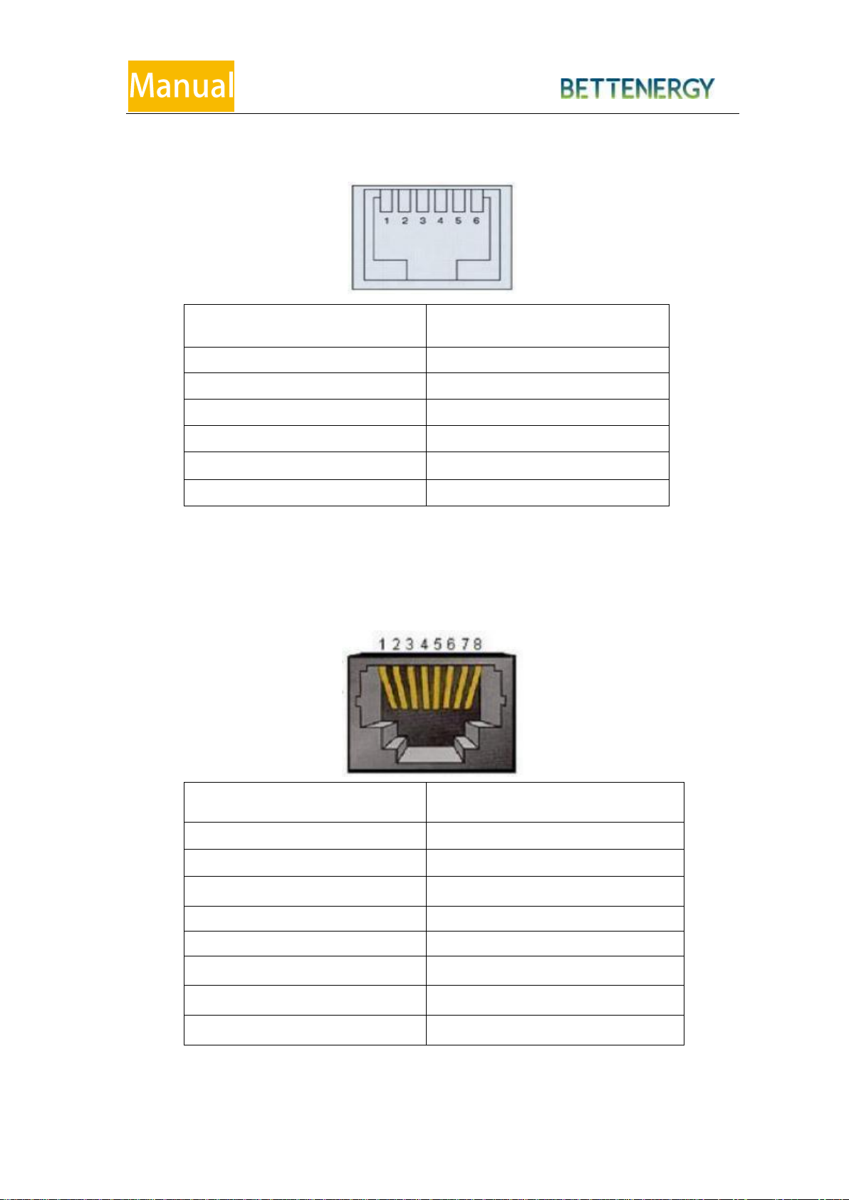
5.2.4 The CAN port
Interface
Definition Description
Pin1
The NC(is empty)
Pin2
The NC(is empty)
Pin3
The NC(is empty)
Pin4
CANH
Pin5
CANL
Pin6
The NC(is empty)
Pin7
The NC(is empty)
Pin8
The NC(is empty)
The CAN communication terminal (RJ45 port) follows the CAN protocol and
connects to the inverter CAN communication
1. The BMS controls the charging current / charge voltage ordischarge current /
discharge voltage of the inverter, via CAN, based on the battery voltage and
battery temperature.
2. If the battery capacity is less than 8%, the BMS control inverter forces the
charges via CAN communication to avoid damage to the battery due to deep
discharge.
3. If the SOC is below 97% for a consecutive month, the BMS controlsthe
inverter via CAN communication, charging the battery fully to correct the
SOC error.
POWERBOX
15
5.2.5 The RS232 Port
Interface
Definition Description
PIN1
NC
PIN2
NC
PIN3
RS232 tx
PIN4
RS232 rx
PIN5
GND
PIN6
NC
The RS232 communication terminal (RJ45 port) follows the RS232 protocol for
commissioning or service by the manufacturer or professional engineer.
5.2.6 RS485-1
Interface
Definition Description
Pin1
RS485-B
Pin2
RS485-A
Pin3
RS485-GND
Pin4
NC
Pin5
NC
Pin6
RS485-GND
Pin7
RS485-A
Pin8
RS485-B
The RS485-1 communication terminal (RJ45 port) follows the RS485 protocol to
_
_
POWERBOX
16
connect the inverter RS485 communication.
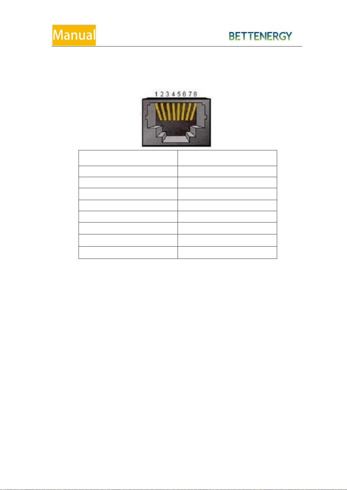
5.2.7 RS485-2
Interface
Definition Description
Pin1
RS485-B
Pin2
RS485-A
Pin3
RS485-GND
Pin4
The NC(is empty)
Pin5
The NC(is empty)
Pin6
RS485-GND
Pin7
RS485-A
Pin8
RS485-B

POWERBOX
17
6 The Installation Guide
Installation Procedure Flowchart
6.1 Checking before Installation
6.1.1 Check the packing
Packaging materials and components may be damaged during transportation.
Therefore, check the outer packaging material before installing the battery. Check the
surface of the packaging material for damage, such as holes and cracks. If any damage is
found, do not unpacking the battery and contact the dealer as soon as possible. It is
recommended that you remove the packaging material within 24 hours before installing
the battery.
6.1.2 Check the Deliverables
After opening the packing box, check that the random attachment is complete. If any
damage or missing parts is found, please contact the dealer.
The following table shows the random components and mechanical components.

POWERBOX
18
Packing list
No.
Picture
Quantity
Description
1
1
Battery pack
2
2
Case fixing bracket
3
8
Chassis hanging ear
screw (M4*10)
4
4
Case mounting ear
retaining screws
(M6*12)
5
2
Orange quick connector
6
2
Black quick connector
7
1
Certificate
8
1
Inspection report
9
1
Quality guarantee

POWERBOX
19
Manufacturing of the power cable terminal:
(A)Copper-core wire (B)The insulation layer (C)Heat-shrink tube
(D)Hydraulic pliers (E)Hot-air gun
(A)Copper-core Line (B)Insulation layer (C)Protective cover
(D)Hydraulic pliers

POWERBOX
20
6.2 Tools
Type
Tools
Installation
Tools
Knife
Hammer drill
Socket wrench
Rubber mallet
Cross Screwdriver
Incinometer
Measuring tape
Protective
Equipments
ESD gloves
Safety goggles
Anti-dust
respirator
Safety shoes
This manual suits for next models
1
Table of contents
Other BETTENERGY Camera Accessories manuals


