Better Packages 555e User manual
SERVICE MANUAL
555e
REV 10 10072022
Model BP555e
Tape Dispenser
BP555eSERVICE MANUAL
BETTER PACKAGES
®
4 Hershey Drive Ansonia, CT 06401
Web Site: www.betterpackages.com
File Name: BP555e Service Manual Rev7.doc


Rev 9 2022
3
This manual is a non-controlled document
Informaon contained in this manual does not constute a warranty of performance. Furthermore Beer Packages
reserves the right to revise this publicaon.
Beer Packages assumes no liability for any losses or damages incurred as a result of informaon contained in this
manual.
Proprietary noce
This publicaon contains informaon proprietary and condenal to Beer Packages. Any reproducon, disclosure, or
use of this publicaon is expressly prohibited as Beer Packages may otherwise authorize in wring.
This manual contains part numbers for the 555es and 555esa model machines only. If you have a dierent model
machine please contact Beer Packages Machinery Support at (877) 447-4832 Opon 4 or [email protected].
If you or your service team choose, machines may be sent in through your preferred distributor for maintenance by an
authorized Beer Packages service technician.
A list of all current distributors may be found on our website www.beerpackages.com.
Beer Packages
4 Hershey Dr
Ansonia, CT 06401
(800) 237-9151

4
Rev 9 2022
Table of Contents
Technical Data 6
Troubleshoong 7
Tape Jams 7
Tape Strips Too Short 8
Tape Strips Too Long 9
Tape Feeds Slowly 9
Not Feeding Tape 10
Maintenance & Repair 11
Preventave Maintenance 12
Removal of Covers 13
Fuses 14
Control Board Replacement 15
Feed Wheel/Blade Height Adjustment 16
Keypad/Keypad Membrane Replacement 17
Feed Wheel Replacement 18
Front and Rear 20
Cover Assembly 20
Blade Oiler 21
Solenoid Repair 22
Solenoid Replacement 24
Thermostat Replacement 26
Heater Replacement 28
Motor Replacement 29
Motor Chain Adjustment 30
Connector Plate Assembly 31
Shear Blade Replacement 32
Length Sensor Replacement 34
Tape Sensor (ESA Only) 35
Parts Lisng 36

Rev 9 2022
5
Safety Precauons
Must read before servicing equipment.
• This machine is designed for sealing cartons with water acvated tape. Any other use will void all warranes and
any responsibility or liability of Beer Packages, Inc.
• Read all Safety Precauons and Operang Instrucons before powering on and using the machine.
• Any operator of this machine must be fully trained in the operaon and safety.
• In the event of a malfuncon or breakdown, grounding provides a low resistance path for electric current to
reduce the risk of electric shock. This machine is equipped with an electric cord having an equipment-grounding
conductor and a grounding plug. The plug must be plugged into a matching outlet that is properly installed and
grounded in accordance with all local codes and ordinances.
• Before connecng the machine to the power mains verify that the electrical rangs of the machine match the
electrical supply intended for connecon, otherwise do not connect. If the correct power is not available contact
the reseller.
• Before maintenance or repair, disconnect the power cords from the electrical supply and protect the cables from
any possible accidental connecon carried out by unauthorized personnel.
• Keep the machine away from children and from personnel who are not authorized or adequately instructed in
the use of it.
CAUTION:ALWAYS DISCONNECT YOUR MACHINE FROM ALL ENERGY SOURCES
AND WEAR ALL PROPER PERSONAL PROTECTIVE EQUIPMENT (PPE) PRIOR TO
CONDUCTING ANY MAINTENANCE.

6
Rev 9 2022
20”Lx12.5”Wx12”H (51 x 32 x 30 cm)
Up to 45” (114 cm) per second
2 pints 2 oz. (1 liter)
32 lbs. (15 kg)
555es, eSA, eL, eLA – 115 volts, 60 Hz, 4 Amps
555eMA, eFA – 220/240v, 50 Hz, 2 Amps
555eJA – 100V, 50/60 Hz, 4 Amps
1-1/2” to 3” (3.8 to 7.7 cm) wide
Up to 1000 . of tape
Up to 10” diameter roll(25 cm)
Size:
Dispensing Speed:
Water Bole Capacity:
Shipping Weight:
Power Requirements:
Tape Width:
Maximum Roll Size:
Technical Data
All specicaons subject to change without noce
Model
BP555e S
BP555e SA
BP555e L
BP555e LA
BP555e M
BP555e MA
BP555e J
BP555e JA
BP555e F
BP555e FA
Length, Unit of Measure
Short, Inch
Short, Inch
Long, Inch
Long, Inch
Metric
Metric
Metric
Metric
Short, Inch
Short, Inch
Voltage
115V 60Hz
115V 60Hz
115V 60Hz
115V 60Hz
230V 50Hz
230V 50Hz
100V 50/60Hz
100V 50/60Hz
230V 50Hz
230V 50Hz
Country Connent Used
US/Canada (1)
US/Canada (1)
US/Canada (1)
US/Canada (1)
Europe (2)
Europe (2)
Japan (1)
Japan (1)
Far East (1)
Far East (1)
1) Tape gummed side in, (2) Tape gummed side out

Rev 9 2022
7
Troubleshoong Tape Jams
• Interference when Tape in Moon
◊ Operator grabs the tape before it stops dispensing
◊ Tape hits box or other object while dispensing.
• Tape Path Dirty
◊ Tape path must be free of dirt, glue and tape. Keep in mind that the feed wheel is pushing tape forward
aer leaving it. Therefore, a tape piece or other obstrucon will divert the tape from its normal path and will
cause a jam.
• Tape Pieces Stuck in Machine
◊ Aer a tape jam or at the end of a roll a tape a small piece of tape may be le in the machine tape path.
Verify that any piece of tape, however small, has been removed from the machine aer clearing a tape jam.
• Brushes Posioned Incorrectly
◊ The brush ferule must be snapped under retaining clip.
◊ Long bristle edge must face towards the front of machine
• Moistening Brushes Worn
◊ Hole or depression worn into surface of bristles causing tape to catch
◊ Clumps of glue interfering with tape moon
◊ This issue may be worse when the brushes are dry, and may be ne aer fully moistened.
• Lower Heater Plate
◊ Not snapped up and together with heater plate
◊ Bent – Lower plate should not be curved so as to create a pinch point with the heater plate
◊ Dirty – glue or tape stuck to top of plate
• Roll Guide Mis-adjusted
◊ Roll guides in wrong slot with too much side clearance which allows roll to wobble excessively.
◊ Roll Guides too ght against sides of roll causing excessive drag.
• Blade Height Needs Adjusng (feed wheel adjustment too ght)
◊ Tape hing blade
◊ Tape jumping over blade or le -hand corner of tape folded over
• Tape issues – damaged, frayed, excessive curl, extremely thin or thick, requiring feed wheel adjustment.
• Upper Tape Plate – missing, bent, or incorrect posion
◊ Tape must move freely under the plate, all the way up to the blade.
• Poor Cung
◊ If the blade is cung poorly or incompletely
• Heater Plate Bent
• Blade Oiler - felt separang from holder and interfering with tape

8
Rev 9 2022
Troubleshoong Tape Strips Too Short
The machines measures the tape length by counng the number of pulses from the length encoder. Each me one of
the small cutouts in the encoder wheel passes in front of the opcal switch a pulse is produced. When the programmed
number of pulses is reached the machine turns o the motor and cuts the tape. The most likely cause for short lengths
is the feed wheel slipping on the tape.
• Slippage
If the blade height is not adjusted correctly sucient pressure may not be exerted on the tape by the feed wheel.
To test this:
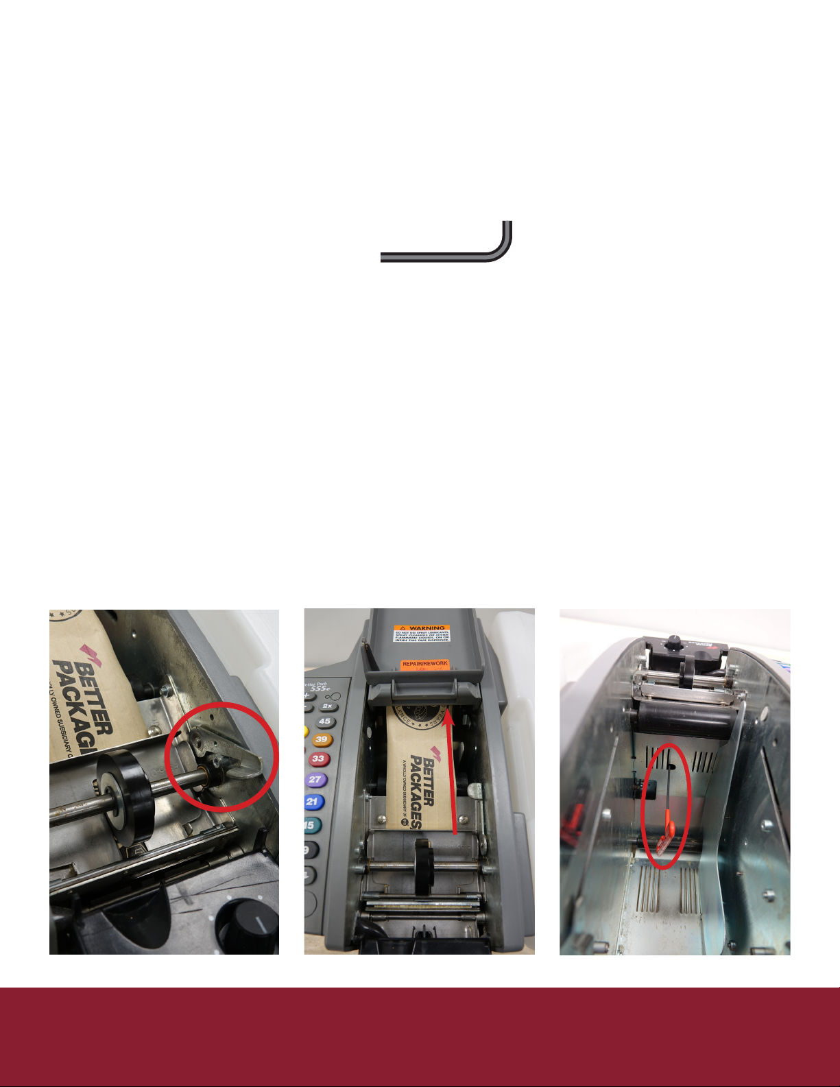
1. Open the cover and insert a strip of tape under the Feed Wheel, as if you are loading tape.
2. To the right is a small lever, li up on this lever. The Blade should rise when this happens.
3. Aempt to pull the tape out from under the Feed Wheel.
a. If it removes too easily the Feed Wheel will need to be ghtened
b. If you cannot remove the tape the Feed Wheel is too ght and will need to be loosened.
c. If the tape can be removed with a constant pull force pull force, clean the feed wheel
Adjust blade height if needed.
Reference the secon Feed Wheel / Blade Height Adjustment for instrucons
A dirty or oily feed wheel may slip on the tape. Clean the surface of the feed wheel that contacts the tape with a mild
cleaner and a clean cloth.
If le hand corner of tape is folded over the blade is not high enough for the tape to pass through unobstructed, adjust
the blade height.

Rev 9 2022
9
Troubleshoong Tape Strips Too Long
If the controller board does not see all the encoder pulses the tape produced will be long.
• Encoder Problem
◊ Verify the length encoder is plugged into the controller board and none of the wires are broken.
▪ If a bad encoder sensor (opcal switch) is suspected, swap in a known good one to conrm.
• Controller Board
◊ If the encoder is good, then the controller board is suspect, swap in a know good controller board to conrm.
If there is a constant feed or extremely long tape pieces either the length encoder or controller board will need to be
replaced.
Tape Feeds Slowly
If the tape roll is free to turn and there is no tape jammed in the machine, the most likely reason is bad tape weng
brushes. Other issues could be
• Motor brushes worn
◊ Brushes will supply years of use under normal condions, but may wear out and need to be replaced.
• Motor defecve
◊ If motor brushes are good the motor may need to be replaced.
• CodeTaper
◊ If a CodeTaper is being used, verify tape is not binding in it and that the tape can be pulled freely through it.
• Low line voltage
◊ Low line voltage can slow the motor speed down as much as 20%, but it will sll dispense quickly. Usually the
solenoid will chaer or the machine will stop dispensing tape all together by the me the line voltage is low
enough to cause the tape to feed extremely slow.

10
Rev 9 2022
Troubleshoong Not Feeding Tape
If the power indicator lamp is illuminated but the motor does not start check the following:
• Interlock Circuit
◊ Top cover open
▪ Verify the top cover is fully closed and seated properly
◊ Magnet missing
▪ Verify that the small magnet located in the top cover is present. It should be found opposite of the
magnet reed switch (1/2” diameter circular disk, or 1”X1/4” black rectangular switch depending on
producon year) in the le side of the from when the cover is completely closed. Only one magnet will
be in either locaon. (Figure 1)
◊ Interlock switch circuit not plugged in
▪ Verify that the interlock reed switch is plugged into the controller board at the connector marked
“interlock.”
Figure 1

Maintenance
Repair
Always unplug your machine when performing service.
Rev 9 2022
11
&
CAUTION:ALWAYS DISCONNECT YOUR MACHINE FROM ALL ENERGY SOURCES
AND WEAR ALL PROPER PERSONAL PROTECTIVE EQUIPMENT (PPE) PRIOR TO
CONDUCTING ANY MAINTENANCE.
12
Rev 9 2022
Maintenance & Repair Preventave Maintenance
Suggested preventave maintenance schedule:
Weekly
• Wash water brushed with mild soap; rinse well.
• Clean any accumulated tape dust with a dry brush or blower.
• Wash water tank with mild soap; rinse well.
Monthly
• Clean accumulated glue from blades using a scraper. (Don’t scrape the cung edge, the blade may dull and need
replacement). Cauon: The blade is sharp and can cut easily, be careful working around it.
• Apply light coang of light machine oil to back of blade.
• Add a few drops of light machine oil to felt pads.
Annually
• Thoroughly clean all accumulated pieces of tape, tape dust and any other foreign material from inside the
machine with dry brush or blower.
• Clean boom of heaters and pressure plates of accumulated glue.
• Oil upper and lower blades lightly with light machine oil.
• Clean all covers with damp rag.
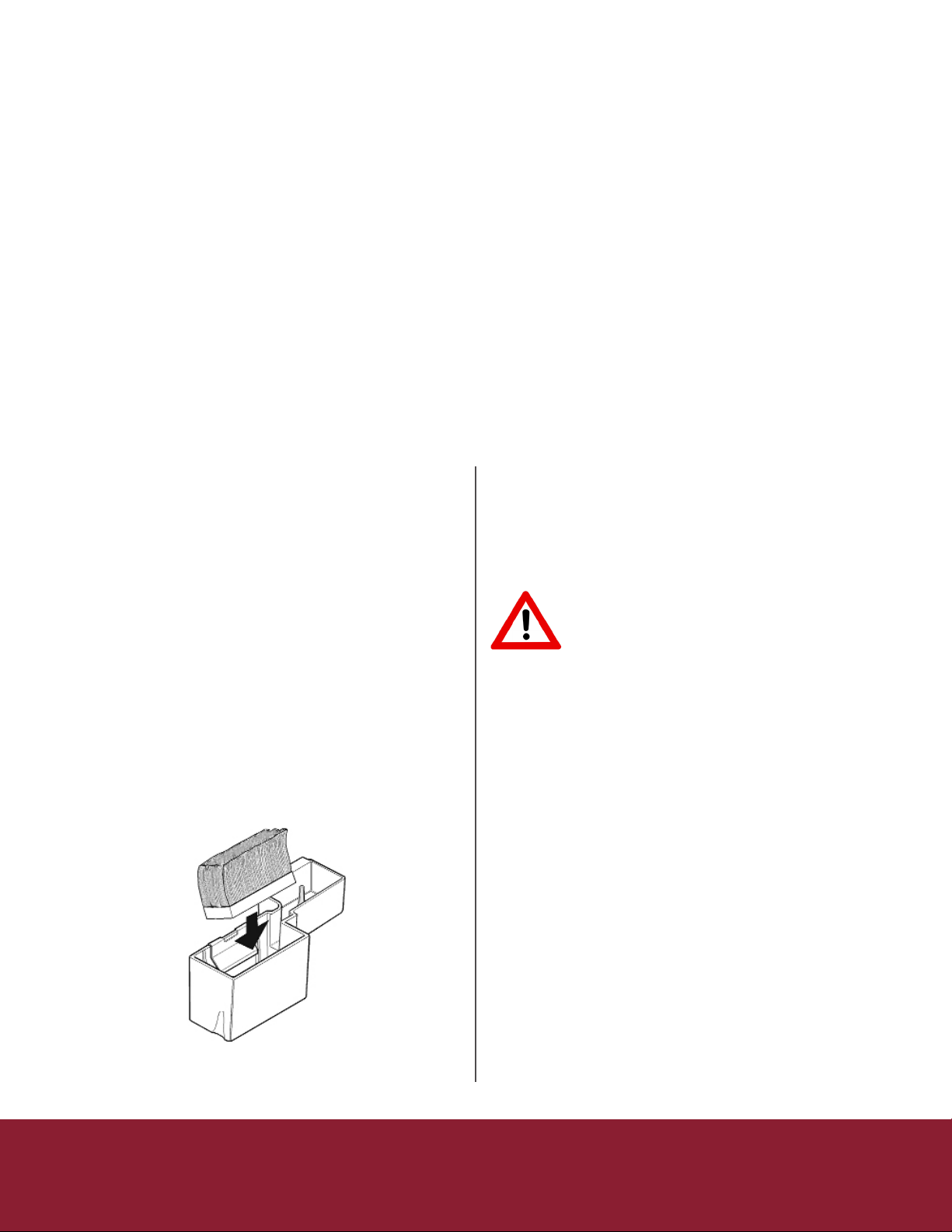
Washing brushes
Water Brushes: Glue from the tape may accumulate and
reduce the eecveness of the moistening system. Wash
brushes weekly with mild soap.
To remove any old dried adhesive, you will need to
lt the brushes to clear the retaining bracket. Be sure to
replace the brushes in the tank correctly. See Figure 14-1.
Facing the brushes in the wrong direcon can result in
poor moistening and tape jamming.
Place the brush into an empty water tank. The brush must
be posioned with the longer bristles facing away from the
machine. When unsecured the top of all bristles should be
parallel with the top side edge of the water tank.
Firmly press the brush straight down. The brush base should
be ghtly pinched by the retaining bracket, keeping the brush
secured in the tank. Bristles should remain parallel with side
top edge of the water tank.
Cleaning the shear blades
For the dispenser to cut the tape well, blades need to
be free of adhesive, dust etc. These materials need to be
cleaned from the blade.
CAUTION: BE SURE THE
DISPENSER IS OFF BEFORE
PERFORMING ANY CLEANING
OPERATIONS. BLADE IS SHARP.
Adjusng the amount of water applied to the tape:
• Adjust the height of the water bole:
◊ Higher to apply more water
◊ Lower to apply less water
• Never use any dispenser for water-acvated tape
without a water bole.
• Do not add water to the water bole “whenever it
looks low”. This will always:
◊ Cause over-weng when the tank is rst lled
◊ Cause under-weng when it needs to be
relled
Figure 14-1
Rev 9 2022
13
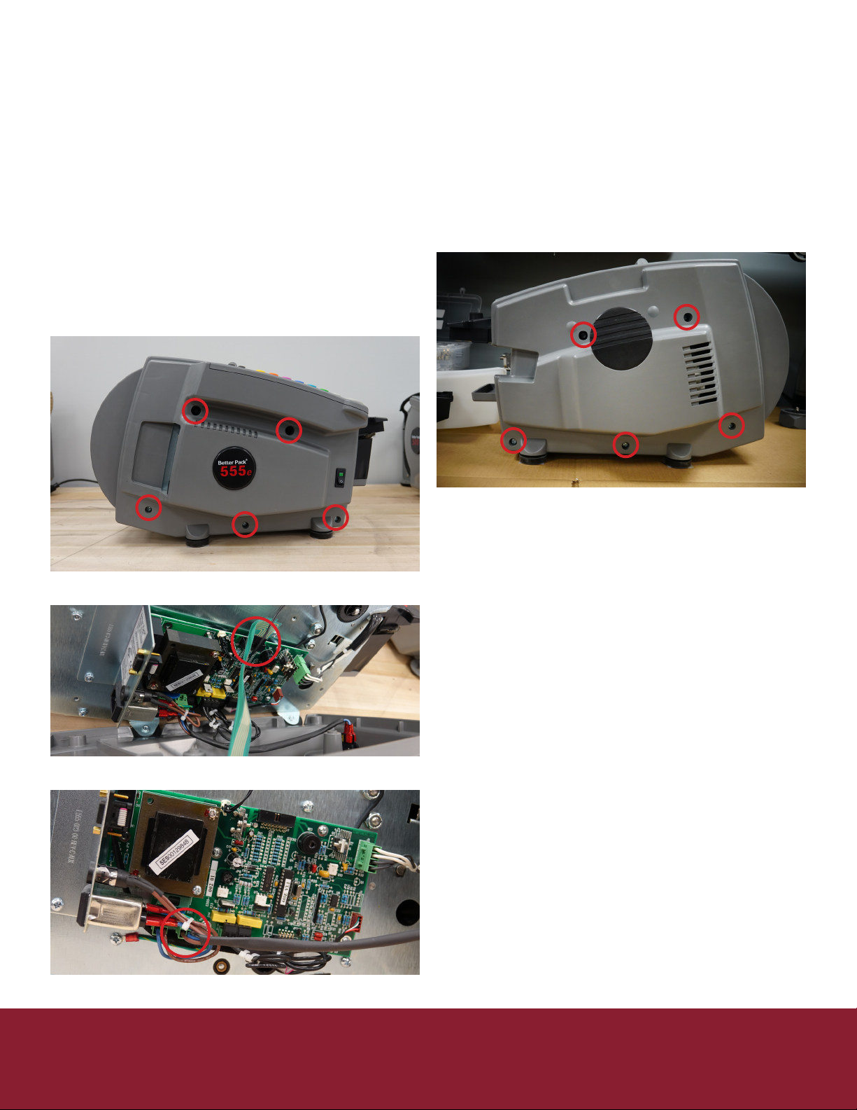
Maintenance & Repair Removal of Covers
This will act as the basic plaorm of how to remove the le and right covers from the machine safely they are the rst
steps in almost all of the procedures. Removing the covers is the rst step in many maintenance procedures.
Removal of the le cover
1. Unplug the machine
2. Remove water bole, tank and brushes
3. Remove the 5 screws holding on the le side cover
(Figure 15-1)
a. Be cauons as the keypad ribbons could
tear
4. Remove the keypad ribbons (Figure 15-2)
5. Remove the switch connector from the
controller board (Figure 15-3)
Removal of the right cover
1. Unplug the machine
2. Remove water bole, tank and brushes
3. Remove the 5 screws holding on the right side
cover (Figure 15-4)
Figure 15-1
Figure 15-4
Figure 15-2
Figure 15-3

14
Rev 9 2022
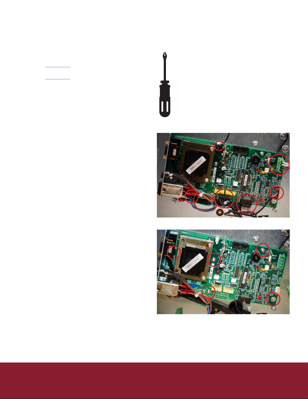
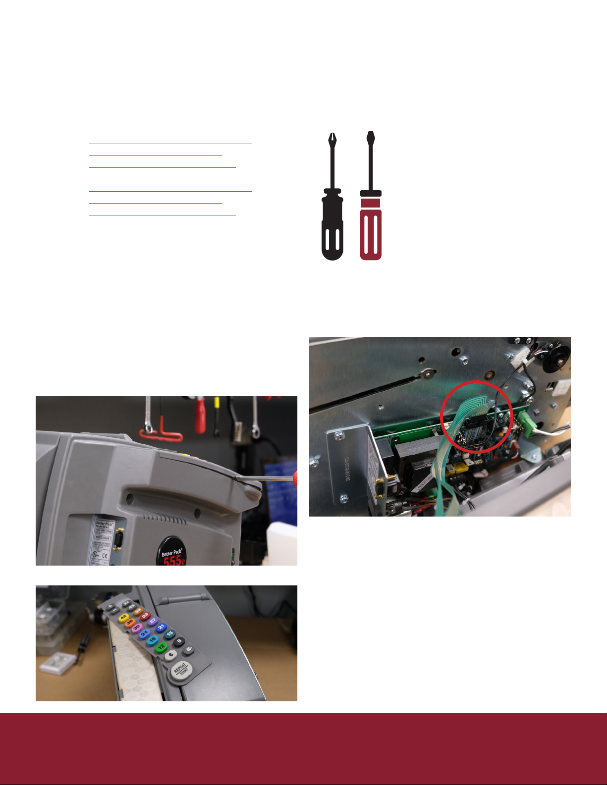
Maintenance & Repair Fuses
There are two fuses located in the 555e series machine. One fuse is accessible and located on the connector plate,
outside of the machine above the power connector. Another fuse is located on the controller board just aer the power
connector and below the transformer.
Tools needed:
• Flat head screwdriver
• Phillips head screwdriver
To change the fuse on the connector plate (part number ST-2341K)
1. Unscrew the fuse holder (Figure 16-1) (at head screwdriver)
2. Remove old fuse and discard
3. Replace fuse with new one
To change the fuse on the controller board (part number ST-2128)
1. Remove the le side cover (Philips head screwdriver) by removing 5 screws (Figure 16-2)
2. Unplug keypad ribbon(Figure 16-3)
3. Remove old fuse with at head screwdriver and discard (Figure 16-4)
4. Replace fuse with new one
5. Plug keypad back in
6. Replace le side cover
Figure 16-1
Figure 16-2 Figure 16-3 Figure 16-4
Rev 9 2022
15
Part Numbers
• ES Model
◊ E55500201
• ESA Model
◊ E55500101
Tools Needed
• Philips head screwdriver
Procedure
1. Unplug Machine
2. Remove the water bole, and tank assembly
3. Remove le side cover (5 Philips screws) be careful as the ribbons connecng the keypad can be ripped easily.
4. Lay machine on its right side
5. Disconnect all connectors (Figure 17-1)
a. Power in
b. Power Switch
c. Solenoid
d. Motor
e. Heater
f. Length Sensor
g. RS232
h. Tape Sensor (ESA Model Only)
6. Remove 5 Philips screws holding the board to the
frame (Figure 17-2)
7. Remove board from machine
8. Place new board in machine
9. Screw in 5 Philips screws into the 5 open spots on
the board
10. Plug in all corresponding connectors
a. Power in
b. Power Switch
c. Solenoid
d. Motor
e. Heater
f. Length Sensor
g. RS232
h. Tape Sensor (ESA Model Only)
11. On le cover plug keypad ribbons back into
controller board
12. Be sure not to miss any pins as this will eect the
length selected
13. Reinstall le cover be sure not to pinch or drive a
screw through the keypad ribbons.
14. Replace water tank, brushes, and water bole
Maintenance & Repair Control Board
Replacement
Figure 17-1
Figure 17-2
16
Rev 9 2022
Maintenance & Repair Feed Wheel/
Blade Height Adjustment
When a dispense key is pressed the tape cuer blade and the lower feed wheel li up. The machine has an adjustment
set screw that sets the height of the blade and lower feed wheel. The adjustment sets the amount of pinch force
between the upper and lower feed wheels. If the feed wheel does not grip the tape suciently, the tape can slip. When
the tape slips an inaccurate measurement of the tape length occurs, resulng in a shorter than normal tape piece. If
short or errac tape lengths occur, the adjustment described below may need to be performed to correct the problem.
Tools needed
• 3/32” Allen wrench 4” long at minimum
Procedure
1. Unplug the machine
2. Open the top cover
3. Install the tape fully
4. On the right side of the feed wheel, li up on the
lever (Figure 18-1)
5. Test the tension on the tape by pulling the tape
out from the back of the feed wheel see Figure
18-2 for direcon
a. If tape is removed easily with lile to no
resistance the feed wheel will need to be
ghtened (clockwise)
b. If tape is very dicult to remove the
feed wheel will need to be loosened
(counterclockwise)
6. Move the lever back to its home posion and
remove the tape from the machine
Figure 18-1 Figure 18-2 Figure 18-3
7. Turn the machine around so you are looking into
the cavity where the tape roll sits
8. Locate the feed wheel adjustment access hole, it
will be between the slide guides (Figure 18-3)
9. Use a 3/32” Allen wrench to make the needed
adjustments from step 4
a. Tighten or loosen in half turn
increments
10. Insert a strip of tape under the feed wheel and
li up on the lever
11. Pull the tape out from under the feed wheel.
b. Proper tension is achieved when the tape is
pulled taught and can be removed with a fair
amount of resistance
a. If this is not how it feels repeat steps
8 through 10 unl proper tension is
achieved
Rev 9 2022
17
Maintenance & Repair Keypad/Keypad
Membrane Replacement
Part Numbers
• ES Model
◊ E55500301 – Membrane and Keypad
◊ E55500301PAD – Keypad Only
◊ E55500301SW – Membrane Only
• ESA/EFA Model
◊ E55500302 – Membrane and Keypad
◊ E55500302PAD – Keypad Only
◊ E55500301SW – Membrane Only
Tools Needed
• Philips head screwdriver
• Flat head screwdriver
Procedure
1. Unplug Machine
2. Remove the water bole, and tank assembly
3. Remove le side cover (5 Philips screws) be
careful as the ribbons connecng the keypad can
be ripped easily.
4. Unplug keypad ribbons from controller board
5. Remove the keypad bezel by inserng a thin
athead screwdriver in-between the keypad
bezel and cover
6. Remove keypad
7. If membrane needs replacement remove it
pulling the ribbon through
8. If membrane replacement is needed place new
membrane feeding ribbon cable through cover
9. Place new keypad
10. Snap the bezel cover back into place
11. On le cover plug keypad ribbons back into
controller board
12. Be sure not to miss any pins as this will eect the
length selected
13. Reinstall le cover be sure not to pinch or drive a
screw through the keypad ribbons.
14. Replace water tank, brushes, and water bole
18
Rev 9 2022
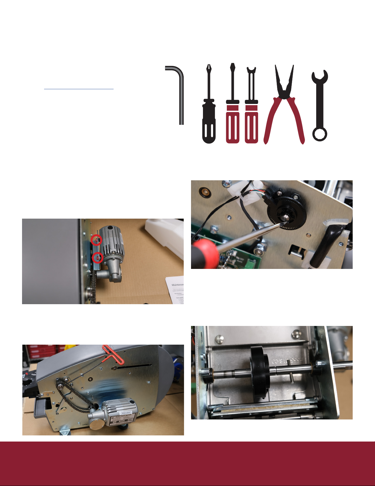
Maintenance & Repair Feed Wheel Replacement
This is considered part of standard maintenance and typically is replaced along with the blade oiler (page XX) and/or
heater assembly (page xx).
Part Numbers
• E55506500 – Feed Wheel
Tools needed
• Philips head screwdriver
• Flat head screwdriver
• 3/32” Allen wrench
• Needle-nose pliers or E-Clip Applicator
• 3/8” wrench
Procedure
1. Unplug the machine
2. Remove water bole, tank and brushes
3. Remove right side cover (5 Philips screws)
4. Remove le side cover (5 Philips screws) be
careful as the ribbons connecng the keypad can
be ripped easily.
5. Unplug keypad ribbons from controller board
6. Loosen the 2 nuts holding the motor to the frame
7. Push the motor closer to the front of machine
giving drive chain some slack
8. Loosen set screw holding drive sprocket onto
feed wheel sha
9. Remove the drive sprocket from the sha
10. With the at head screwdriver li up on the
retaining stop on the encoder wheel while
pressing the sha from the side
11. Using the at head screwdriver remove the
E-clip holding the washer in place, place your
hand over and twist on the screwdriver. This will
help if it ies o so you will not lose it.
12. Slide the washer and old feed wheel o the
sha. Be careful of the retaining pin as it may fall
through the sha.

Rev 9 2022
19
Maintenance & Repair Feed Wheel Replacement
13. Slide new feed wheel on, seat into retaining pin
14. Replace the washer
15. Using an E-clip applicator or needle-nose pliers
replace the E-clip to hold washer and feed wheel
in place.
16. Push sha back through hole on le side while
holding the encoder wheel in place
17. Align the at side of the sha with the
corresponding at in the encoder wheel and
press into place unl you hear the click of the
retaining stop
18. Place the drive sprocket back onto the sha
a. End of sha should sit at end of chamfer on
the inner diameter of the sprocket
19. Tighten set screw on sprocket
20. Push motor back unl drive chain is ght
21. Tighten nuts holding motor in place
22. Replace the right cover (5 Philips screws)
23. On le cover plug keypad ribbons back into
controller board
a. Be sure not to miss any pins as this will eect
the length selected
24. Reinstall le cover be sure not to pinch or drive a
screw through the keypad ribbons.
25. Check feed wheel tension and make any
adjustments needed. See page 17
26. Replace water tank, brushes, and water bole
Connued

20
Rev 9 2022
Maintenance & Repair Front and Rear
Cover Assembly
Part Numbers
• E55509801 – Li Roller Bracket Assembly
• E55503501 – Top Cover Assembly
• E55503401 – Rear Cover Assembly
• E55506000 – Rear Pivot Pin
• E55509000 – Extension Spring
Tools needed
• Philips head screwdriver
• Flat head screwdriver
• E-clip applicator or needle nose pliers
Procedure
1. Unplug machine
2. Remove water bole, tank, and brushes
3. Remove right side cover (5 Philips screws)
4. Remove le side cover (5 Philips screws) be
careful as the ribbons connecng the keypad can
be ripped easily.
5. Unplug keypad ribbons from controller board
6. Using at head screwdriver remove the 2 E-clip
retaining rings holding the bracket assembly to
the right and le side frame.
7. Keep rings and washers in a safe place
8. Using at head screwdriver remove the 2 E-clip
retaining rings holding the rear pin in place from
the right and le side frame.
9. Remove the rear pin
10. Remove the spring from the rear cover,
the assembly should now come free of the
machine body
11. Align the new cover
12. Press the rear pin back into place
13. Using an E-clip applicator or needle nose plier
replace the clips on the pin
14. Replace the spring on the lower cover
15. Replace the washer on the bracket assembly
16. Using an E-clip applicator or needle nose plier
replace the clip on the bracket assembly
17. Repeat step 13 & 14 for opposite side
18. Replace the right cover (5 Philips screws)
19. On le cover plug keypad ribbons back into
controller board
a. Be sure not to miss any pins as this will eect
the length selected
20. Reinstall le cover be sure not to pinch or drive a
screw through the keypad ribbons.
21. Replace water tank, brushes, and water bole
Table of contents
Other Better Packages Dispenser manuals

Better Packages
Better Packages Better Pack 755eS User manual

Better Packages
Better Packages Better Pack 755eMA User manual

Better Packages
Better Packages BP555e User manual

Better Packages
Better Packages PS2A User manual

Better Packages
Better Packages Better Pack 755e Series User manual

Better Packages
Better Packages BP500 User manual


