Kohler 1400976-2-A User manual

Thank You for Choosing KOHLER
Need help? Contact our Customer Care Center.
USA/Canada: 1-800-4KOHLER (1-800-456-4537)
Mexico: 001-800-456-4537
For service parts information, visit kohler.com/serviceparts.
For care and cleaning information, visit kohler.com/clean.
Warranty
This product is covered under the KOHLER® Electronic Faucets, Valves, and
Controls Five-Year Limited Warranty, found at kohler.com/warranty.
For a hardcopy of warranty terms, contact the Customer Care Center.
1400976-2-A2 Kohler Co.

Tools and Materials
Before You Begin
IMPORTANT! Your product may appear dierent than illustrated. The installation
procedure is the same. Consult the specication sheet for rough-in dimensions for
your model requirements.
Follow all local plumbing and building codes.
Soap Requirements
CAUTION: Risk of product damage. The foaming hand soap must have a
dynamic viscosity rating between 1 centipoise – 100 centipoise (cP) measured
in cP or grams/cm-s units. Soaps with a dynamic viscosity greater than 100 cP
can cause premature wear and damage to the soap dispenser components and
may void the product warranty.
Kohler Co. 3 1400976-2-A
Sealant 1" to 1-1/4" Hole Bit
1/4"
Plus:
• Foaming Hand Soap (1 cP – 100 cP)

CAUTION: Risk of property damage. Only use liquid foaming hand soap
that contains no suspended particles or microbeads. Do not use non-foaming
liquid hand soaps, which typically have a dynamic viscosity rating of 1000 cP
– 3500 cP.
CAUTION: Risk of product damage. Do not use alcohol-based soap and/or
soaps with alcohol.
NOTE: Kohler foaming hand soaps are precisely formulated to work with this
product and have a dynamic viscosity rating of 1 cP – 20 cP.
NOTE: See kohler.com for more information on recommended foaming hand soaps.
Precise information on soap material properties and dynamic viscosity rating can be
found on the soap manufacturers published material safety data sheets.
1400976-2-A4 Kohler Co.

Roughing-In
14-1/2"
(368 mm)
Mounting
Surface
4"
(102 mm) Min
Floor
11-1/2" (292 mm) Min
12-1/2" (318 mm) Max
5" (378 mm) Min
Kohler Co. 5 1400976-2-A

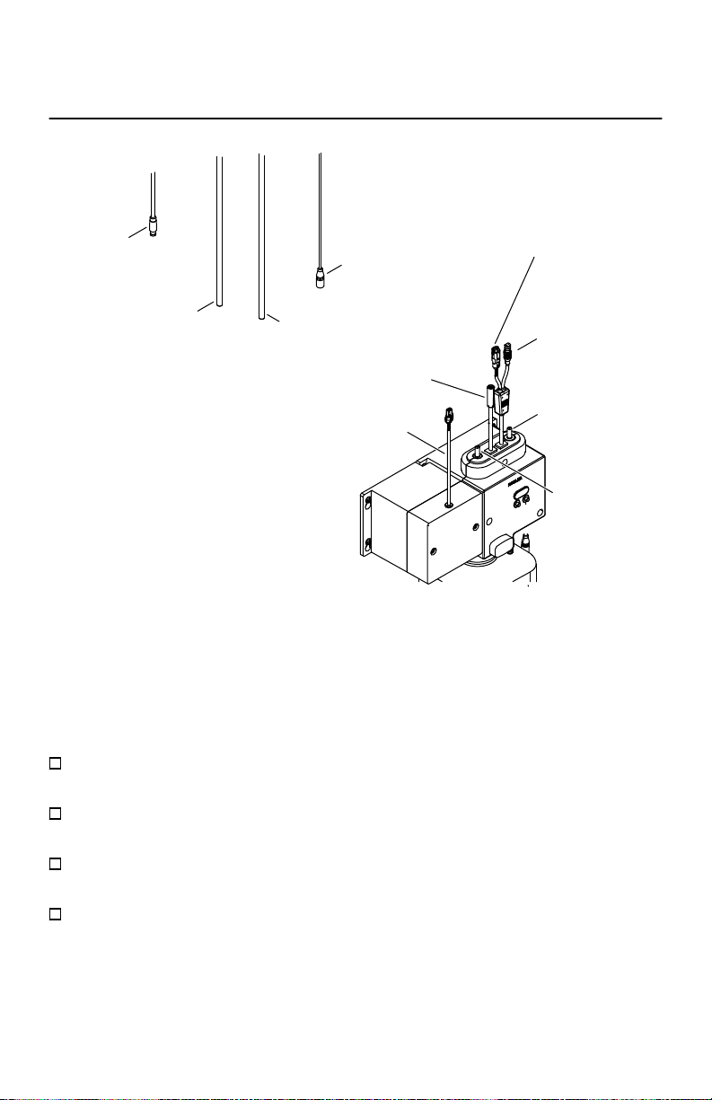
1. Install the Spout
Nut
Tubes Sensor
Threaded
Stud Metal
Washer
Rubber
Gasket
Spout
1" (25 mm) Min -
1-1/2" (38 mm) Max
2-1/2"
(64 mm) Min
A 1" (25 mm) minimum to 1-1/4" (32 mm) maximum diameter mounting hole is
required.
Determine the mounting-hole location.
NOTE: The mounting hardware provided is for a standard deck thickness of 1/4” (6
mm) minimum to 2” (51 mm) maximum. For a deep rough-in installation where deck
thickness is 2” (51 mm) minimum to 4-1/2” (114 mm) maximum, order the deep
rough-in kit from kohler.com/serviceparts.
A 2-1/2" (64 mm) minimum distance is required between the nished wall and the
center of the spout.
A 1" (25 mm) to minimum to 1-1/2″ (38 mm) maximum distance is required
between the sink edge and the center of the spout.
Drill a hole through the mounting surface according to the surface manufacturer’s
instructions.
Insert the spout with tubes and wires through the mounting hole.
From under the sink, slide the rubber gasket and metal washer onto the stud.
If desired, add sealant to the underside of the escutcheon as needed. Wipe away
any excess sealant.
Thread the nut onto the stud and wrench-tighten to secure the spout to the
mounting surface.
1400976-2-A6 Kohler Co.

2. Install the Control Box
Position the control box 11-1/2" (292 mm) minimum to 12-1/2" (318 mm)
maximum below the deck. Check the Specication Sheet for the control box
location.
Mark the location of the mounting holes.
NOTE: The provided wall anchors are for concrete wall installation. Use the
appropriate wall anchors depending on your wall material.
Drill the holes per the anchor manufacturers instructions. If using the provided
wall anchors, drill 1/4” (6 mm) pilot holes.
Aach the control box to the wall as shown.
Secure with the four screws provided.
Kohler Co. 7 1400976-2-A

3. Install the DC Power Unit
Power Cord
Control Box
Power Cord
Battery Box
Ribs
Unthread the screws from the baery box to remove the baery box cover.
NOTE: Do not mix used and new baeries.
Insert four D baeries (provided). Reinstall the baery box cover and secure with
the screws.
Align the grooves on the baery box with the ribs on the side of the control box.
Mark the location of the mounting holes.
NOTE: The provided wall anchors are for concrete wall installation. Use the
appropriate wall anchors depending on your wall material.
Drill the holes per the anchor manufacturers instructions. If using the provided
wall anchors, drill 1/4” (6 mm) pilot holes.
Slide the baery box onto the ribs on the side of the control box. Secure with the
screws.
1400976-2-A8 Kohler Co.

4. Connect the Control Box Wires
Plastic
Tube
Plastic
Tube
LED Assembly
Connector
Power Supply
Connector
Soap Pump
Outlet
Air Pump
Outlet
Sensor
Assembly
Cable
LED
Assembly
Cable
Power
Supply
Connector
Sensor Assembly
Connector
IMPORTANT! Verify that the cables are not pinched when connecting to the control
box.
IMPORTANT! The area in front of the sensor must be free of objects during the 2
minute learning cycle or the soap dispenser may not function properly.
Connect the sensor assembly cable from the spout to the sensor assembly
connector from the control box.
Connect the LED assembly cable from the spout to the LED assembly connector
from the control box.
Connect the power supply connector from the baery box to the power supply
connector from the control box.
Allow 2 minutes for the sensor to cycle through the automatic sensing distance.
Kohler Co. 9 1400976-2-A

NOTE: Once the power supply cords are connected, the base of the soap dispenser
will ash red twice every six seconds. This is normal and is a signal that there is no
soap in the reservoir. After the soap is lled and primed the ashing will stop.
Secure any extra wire under the deck.
1400976-2-A10 Kohler Co.

5. Connect the Tubes
Air Pump
Outlet
Soap Pump
Outlet
Plastic
Tube
Plastic
Tube
NOTE: The plastic tubes are interchangeable. Either tube can be connected to the
soap or air pump outlet.
IMPORTANT! Verify that the tubes are not pinched when connecting the control box
outlets. Do not coil extra tubing. The tubing should not hang below the outlet of the
control box.
Soap Pump Connections
Verify that the plastic tube from the spout is the appropriate length to reach the
control box.
The tube should not hang below the outlet of the control box. Cut the tube if
necessary.
Press the plastic tube onto the soap pump outlet on the control box until the tube
stops.
Verify that the tube is secure.
Kohler Co. 11 1400976-2-A

Air Pump Connections
Verify that the plastic tube from the spout is the appropriate length to reach the
control box.
The tube should not hang below the outlet of the control box. Cut the tube if
necessary.
Press the remaining plastic tube onto the air pump outlet on the control box until
the tube stops.
Verify that the tube is secure.
1400976-2-A12 Kohler Co.

6. Fill the Soap Reservoir
Soap Reservoir
(Refillable)
Dispensing Tube
Check
Valve
NOTE: The 1600 ml soap reservoir is included. Refer to kohler.com/serviceparts for
the optional 800 ml soap reservoir.
For 800 ml soap reservoir boles, remove the check valve from the dispensing
tube. Cut 2” (51 mm) from the dispensing tube so that the tube ts without any
coiling. Reinstall the check valve.
NOTE: Refer to the Soap Requirements section for more information on the soap
requirements for this product.
IMPORTANT! Rinse the empty soap reservoir with clean warm water before rst
use.
Fill the soap reservoir with KOHLER brand foaming soap or foaming soap with
1 cP – 100 cP to the “Max Fill” line. Do not overll the soap reservoir.
Insert the dispensing tube from the control unit into the soap reservoir.
Press the soap reservoir into place until an audible click is heard.
Kohler Co. 13 1400976-2-A

7. Prepare the Soap Dispenser
Spout
Priming
Button Sensor
Flash
Sensor Range
Button
Press the priming buon located on the control unit until the soap streams from
the spout nozzle – approximately 10 seconds.
1400976-2-A14 Kohler Co.

8. Set the Volume of Soap Dispensed
A
0.6 ml
Rubber
Cover 800 ml
Soap
Counter
1600 ml
Volume
Switches
Up
Down
B
1.0 ml
C
1.6 ml
D
2.0 ml
IMPORTANT! Four options are available to control the amount of dispensed soap.
The desired option is set by moving the volume switches to an up or down position.
NOTE: The dispenser comes equipped with a 1600 ml reservoir, and the soap counter
is set to the 1600 ml position. If an 800 ml reservoir is used, move the soap counter to
the 800 ml position.
Lift the rubber cover to access the control switches.
Set the position of the two volume switches for the desired volume of soap
dispensed. Refer to the seings shown above.
Verify that the soap counter switch is set to the correct position for your reservoir
size.
Refer to the chart below for the approximate number of dispenses available based
on the volume seing and a full 800 ml or 1600 ml reservoir.
Kohler Co. 15 1400976-2-A

Seing
Soap Volume
Dispensed Soap Count(1600 ml) Soap Count(800 ml)
A 0.6 ml 2400 1200
B 1.0 ml 1440 720
C 1.6 ml 900 450
D 2.0 ml 720 360
Close the rubber cover.
1400976-2-A16 Kohler Co.

9. Set the Sensor Range
Spout
Priming
Button Sensor
Flash
Sensor Range
Button
NOTE: The default sensor distance is 2-3/4" (70 mm) +/- 3/8" (10 mm).
Press and hold the sensor range buon for 2 seconds until the sensor ashes red.
NOTE: The sensor range is 1” (25 mm) – 4” (102 mm).
Hold an object at the desired distance in front of the sensor.
The light will ash red to signal that the sensor range adjustment is complete.
Kohler Co. 17 1400976-2-A

Spout LED Indicators
Spout LED
Indicators
Flashing BLUE
The base of the soap dispenser will ash BLUE every 6 seconds when the voltage is
lower than 4.8 volts. The soap dispenser will continue to dispense soap.
The base of the soap dispenser will ash (twice) BLUE every 6 seconds when the
voltage is lower than 4.5 volts. The soap dispenser will not work. Replace the
baeries.
Flashing RED
The base of the soap dispenser will ash RED every 6 seconds when the soap is
running low. The soap dispenser will continue to dispense soap.
The base of the soap dispenser will lash (twice) RED every 6 seconds when the soap
is empty. The soap dispenser will not dispense soap. Rell the soap reservoir and re-
prime the dispenser.
1400976-2-A18 Kohler Co.

Care and Cleaning
Do not use any abrasive or harsh cleaners to clean the faucets.
For best results, keep the following in mind when caring for your KOHLER product:
Always test your cleaning solution on an inconspicuous area before applying to the
entire surface. Visit kohler.com/clean for KOHLER brand faucet cleaner products.
Wipe surfaces clean and rinse completely with water immediately after applying
cleaner. Rinse and dry any overspray that lands on nearby surfaces.
Do not allow cleaners to soak on surfaces.
Use a soft, dampened sponge or cloth. Never use an abrasive material such as a brush
or scouring pad to clean surfaces.
Upon cleaning other areas of the restroom be sure the sensor lenses are protected
from other cleaning chemicals/solvents to prevent potential damages to the sensor
and/or electronics.
It is recommended to ush the system with warm water every 2 to 3 months.
Remove and clean the nozzle foaming assembly with warm water.
Remove and clean the check valve from the dispensing tube in the soap reservoir
with warm water.
Fill the soap reservoir with minimal amount of clean warm water.
Reaach the soap reservoir to the control box. Press the system prime buon.
Hold the buon down until all of the water has been ushed through the system.
Rell the soap reservoir with the appropriate foaming hand soap. Press and hold
the system prime buon until all residual water is pushed through the pump and
soap is dispensed.
Kohler Co. 19 1400976-2-A

Troubleshooting
This troubleshooting guide is for general aid only. For warranty service, contact your
dealer, wholesale distributor, or call 1-800-4KOHLER.
Symptoms Probable Cause Recommended Action
1. A red LED
light ashes at
the base of the
soap
dispenser
once every 6
seconds.
A. The soap is
running low
(70% of cycle
used after
priming).
A. Rell the soap reservoir with
appropriate foaming hand soap.
Prime the soap dispenser.
2. A red LED
light ashes at
the base of the
soap
dispenser
twice every 6
seconds.
A. The soap is out
or very low (90%
of cycle used
after priming).
A. Rell the soap reservoir with
appropriate foaming hand soap.
Prime the soap dispenser.
3. A blue LED
light ashes at
the base of the
soap
dispenser
once every 6
seconds.
A. The baeries are
running low
(lower than 4.8
volts).
A. Replace the baeries and prime the
soap dispenser.
4. A blue LED
light ashes at
the base of the
soap
dispenser
twice every 6
seconds.
A. The baeries are
out of power
(lower than 4.5
volts).
A. Replace the baeries and prime the
soap dispenser.
1400976-2-A20 Kohler Co.
This manual suits for next models
3
Table of contents
Languages:
Other Kohler Dispenser manuals