Better Water EQASSY60BC-1TNK User manual
Dec 2016 - REA 2327
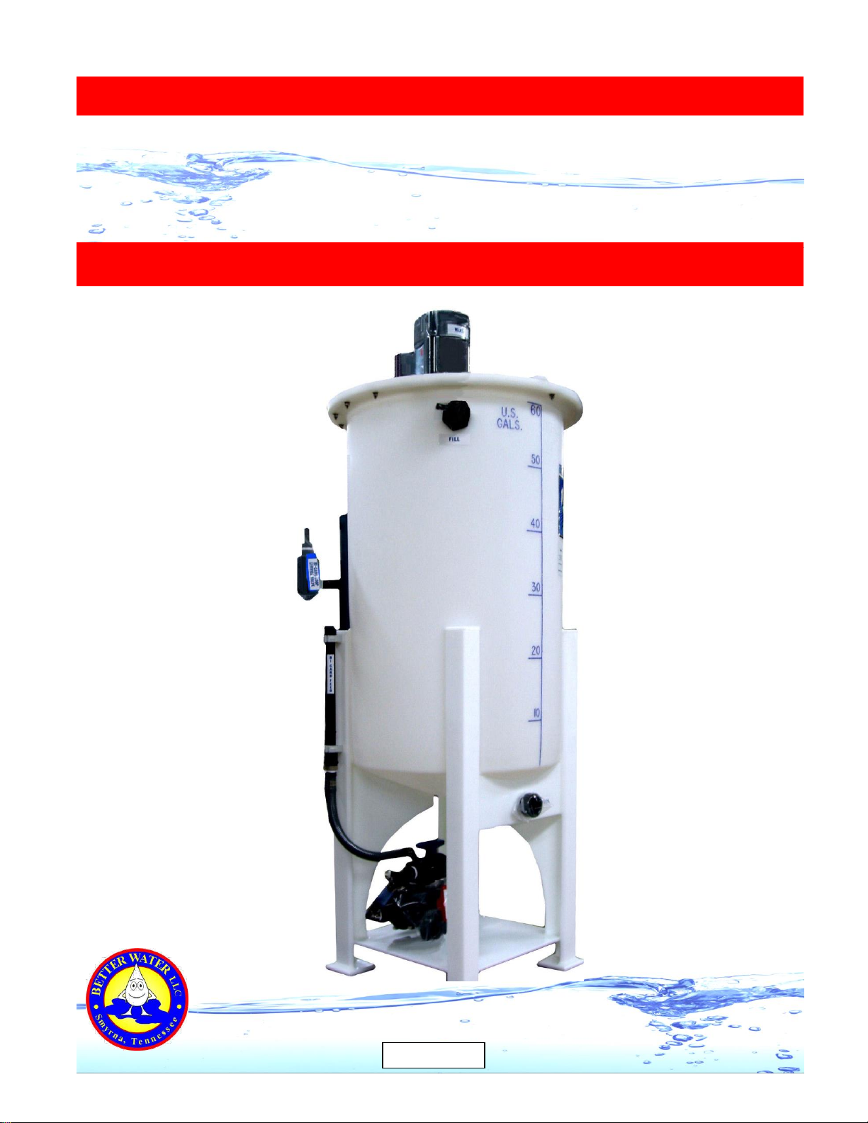
Single Tank Bicarb
Central Mix and Delivery
Service Manual
Better Water LLC
rev. Dec 2016

Dec 2016 - REA 2327
Better Water LLC. All rights reserved.
The content of this manual is the intellectual property of Better Water LLC. It is furnished for the
express use by Better Water LLC, their customers and dealers, for informational use only for operation,
service, and internal training. No part of this manual may be reproduced for distribution, sale, or any
intent other than previously described without the written permission of Better Water LLC. This manual
is subject to change without notice. Better Water LLC assumes no responsibility or liability for any error
or inaccuracies that may appear in this documentation.
Adobe and Acrobat are registered trademarks of Adobe Systems, Inc.
Better Water LLC; 698 Swan Dr; Smyrna, TN 37167; www.betterwater.com

Better Water LLC; rev. Dec 2016
Single Bicarb Tank, Central Mix and Delivery Service Manual
TABLE OF CONTENTS
Our Company ……………………………………………………………………………………... 01
- Contact Us ……………………………………………………………………………………….. 01
- Technical Phone Support ………………………………………………………………………. 01
- Technical Support Info Online …………………………………………………………………. 01
- Specific Contacts ……………………………………………………………………………….. 02
Introduction ………………………………………………………………………………………… 02
Warnings & Cautions ………………………………………………………………………..…... 03
Models ……………………………………………………………………………………………… 04
- Important Information for Support ……………………………………………………………... 04
- Model Changes Relevant for Support and Replacement Parts ……………………………. 05
Single Bicarb Unit
- Front View ……………………………………………………………………………………….. 07
- Back View ……………………………………………………………………………………….. 08
- Lid and Mounting Hardware …………………………………………………………………… 09
- Mixer Motor Mounts …………………………………………………………………………….. 10
- Mixer Motor, Shaft, & Propellers Diagram ……………………………………………………. 11
- Replacing Propellers, Shaft, and/or Coupling ………………………………………………... 12
- Replacing a Mixer Motor ……………………………………………………………………….. 13
- Return-to-Tank Fitting / Drop-Down Tube …………………………………………………… 14
- Fill Inlet Connections …………………………………………………………………………… 15
- Verifying Float Switch Functionality …………………………………………………………… 16
- Replacing Float Switches ………………………………………………………………………. 17
- Replacing Proximity Sensors ………………………………………………………………….. 18
- Jug Fill Subassembly …………………………………………………………………………… 19
- Replacing the Pump ……………………………………………………………………………. 20
- Pump Mounting Hardware ……………………………………………………………………… 21
- Plumbing Header and Tank Diagram …………………………………………………………. 22
- Plumbing Header ………………………………………………………………………………... 23
- Bicarb Unit Valves Descriptions ……………………………………………………………….. 24
- Bicarb Unit Flow Diagram ………..…………………………………………………………….. 25
Control Box
- Front View ……………………………………………………………………………………….. 26
- Inside Box View, pre January 2005 …………………………………………………………… 27
- Inside Box View, post January 2005 ………………………………………………………….. 28
- Inside Lid View ………………………………………………………………………………….. 29
- Wiring Schematic ……………………………………………………………………………….. 30
Related Replacement Parts ……………………………………………………………………... 31
Limited Warranty Terms and Conditions ……………………………………………………….. 35
Appendix B, Technical Service Bulletins ……………………………………………………… 37
- TSB 2016001: Frequency for Cleaning Bicarbonate Mixing Units .……………………….. 38
Better Water LLC; rev. Dec 2016
Single Bicarb Tank, Central Mix and Delivery Service Manual
Better Water LLC; 698 Swan Dr; Smyrna, TN 37167; www.betterwater.com
Visit our website to see our complete product line of
water purification products!
www.betterwater.com

Better Water LLC; rev. Dec 2016
Page 1 of 40
Single Bicarb Tank, Central Mix and Delivery Service Manual
0
Our
Company
Contact
Us
Technical
Phone
Support
Technical
Support
Info
Online
Better Water LLC is a leading integrated manufacturer of water treatment
equipment and components for the industrial, commercial and institutional
markets.
Located in Smyrna, Tennessee,
Better Water LLC continues its history
of manufacturing and distribution of
equipment specifically designed for the
renal dialysis market.
Founded in 1971, Better Water LLC has
built a reputation for solving our
customers' toughest problems with high
quality products and unmatched service.
Better Water LLC Technical Support:
698 Swan Dr Phone (615) 355-6063, press "1"
Smyrna, TN 37167 Email support@betterwater.com
Phone (615) 355-6063 Customer Service:
Fax (615) 355-6065 Phone (615) 355-6063, press "3"
Email customerservice@betterwater.com
Support is available regarding all Better Water LLC systems,
24 hours a day, 7 days a week.
Normal business hours are Monday through Friday from
8:00 am until 3:30 pm, Central Standard Time (excluding holidays)
Call (615) 355-6063, press "1" for Technical Support
Emergency assistance is available after normal business hours (including
holidays) by calling (615) 708-8627.
Our website, www.betterwater.com, which is updated
frequently, contains a wealth of technical support information on the
SUPPORT tab and includes:
Operator and Service Manuals
Interactive Frequently Asked Questions for Troubleshooting
Consumables and Accessories Lists
Technical Service Bulletins
For your convenience there are also online forms for placing Orders
and requesting Returned Goods Authorization. These are Adobe
forms that can be downloaded and either faxed or emailed to us.

Better Water LLC; rev. Dec 2016
Page 2 of 40
Single Bicarb Tank, Central Mix and Delivery Service Manual
Specific
Contacts
Technical Support Phone (615) 355-6063, option “1”
Email support@betterwater.com
To Place an Order Fax (615) 355-6065
(purchase orders) Email orders@betterwater.com
Phone (615) 355-6063
Customer Service Phone (615) 355-6063, option “2”
(returns) Fax (615) 355-6065
Website www.betterwater.com
Helpful information and forms that can be found on our website:
- Operator & Service Manuals
- Technical Service Bulletins
- Consumables and Replacement Parts List
- Brochures
- Order Form
- Return Goods Authorization Request Form
This Service Manual has been developed for the purpose of ordering
factory replacement parts and for Troubleshooting the Single Bicarb
units. This Service Manual is not intended to replace the Operator
Manual, but serve as a supplement to it. Current versions of this
Service Manual and the Operator Manual as well as other helpful
information can be found on our website at
www.betterwater.com/support.
It is important to understand that the Better Water Bicarb Unit is a Class
II Medical Device and that non-factory replacement parts could affect
the safety, performance, and warranty of the unit.
This manual includes parts lists, photographs, schematics, and
diagrams to assist you in servicing the unit.
Once the this device has been delivered, it is the responsibility of the
Medical Director to ensure that it is used, monitored, and maintained in
such a manner so as to satisfy all applicable standards. Guidelines and
other related information are available from:
- Food and Drug Administration (FDA)
- National Association of Nephrology Technicians/Technologists (NANT)
- Association for the Advancement of Medical Instrumentation (AAMI)
NOTE concerning pictures in this manual:
Pictures of devices and components may vary slightly due to product
changes, and therefore should be for general reference only.
Information concerning their use, functionality, or replacement will not
differ unless noted.
Introduction
Better Water LLC; rev. Dec 2016
Page 3 of 40
Single Bicarb Tank, Central Mix and Delivery Service Manual
WARNINGS
1. It is unsafe to operate or service this device without first reading and understanding the entire
Operator and Service Manuals. Keep this manual and other associated documentation for future
reference.
2. Misuse, improper operation, and/or improper monitoring of this system could result in serious
injury, death, or other serious reactions to patients undergoing hemodialysis treatment.
3. Misuse, improper use, or handling of disinfectants and chemical cleaning solutions could result
in serious injury or even death. You must comply with the information contained in the Material
Safety Data Sheet (MSDS) for the chemical being used.
4. To avoid electrical shock hazard, do not operate this device when the covers or panels are
removed.
5. ELECTROMAGNETIC INTERFERENCE: This device can create and radiate
radio frequency energy and may cause harmful interference if not installed
according to the manufacturer's instructions.
CAUTIONS
1. When used as a medical device, federal law restricts this device to sale by or on the authority
of a physician. Per CFR 801.109 (b)(1).
2. Improper operation of this device could result in a low or no-flow alarm on the dialysis
machines.
3. Misuse or improper operation of this device will void any warranty.
4. Where water is mentioned, unless otherwise noted, it must be AAMI standard quality water.
5. Electrical and plumbing connections must adhere to local statutes and any facility codes.
Connect this device to a proper ground connection in accordance with the National Electrical
Code. Do not remove the ground wire or ground plug. Do not use an extension cord with this
device.
6. Do not remove any Caution, Warning, or any other descriptive labels from the device.
7. Do not operate this device in an explosive environment or in the presence of flammable
materials. Do not use this device to store, mix, or transfer flammable liquids.
8. Movement or vibrations during shipment may cause connections to loosen.
9. Do not operate this unit in an environment where temperatures may be below 50oF or above
90oF.
10.This device should not be used for purposes outside the device’s stated applications,
specifications, or limitations.
Better Water LLC; rev. Dec 2016
Page 4 of 40
Single Bicarb Tank, Central Mix and Delivery Service Manual
MODELS
There are two models of the Single Bicarb unit; the 60 gallon and the 100 gallon. The operation,
service, and replacement parts of these two units are the same with the only difference being the
size of the tanks.
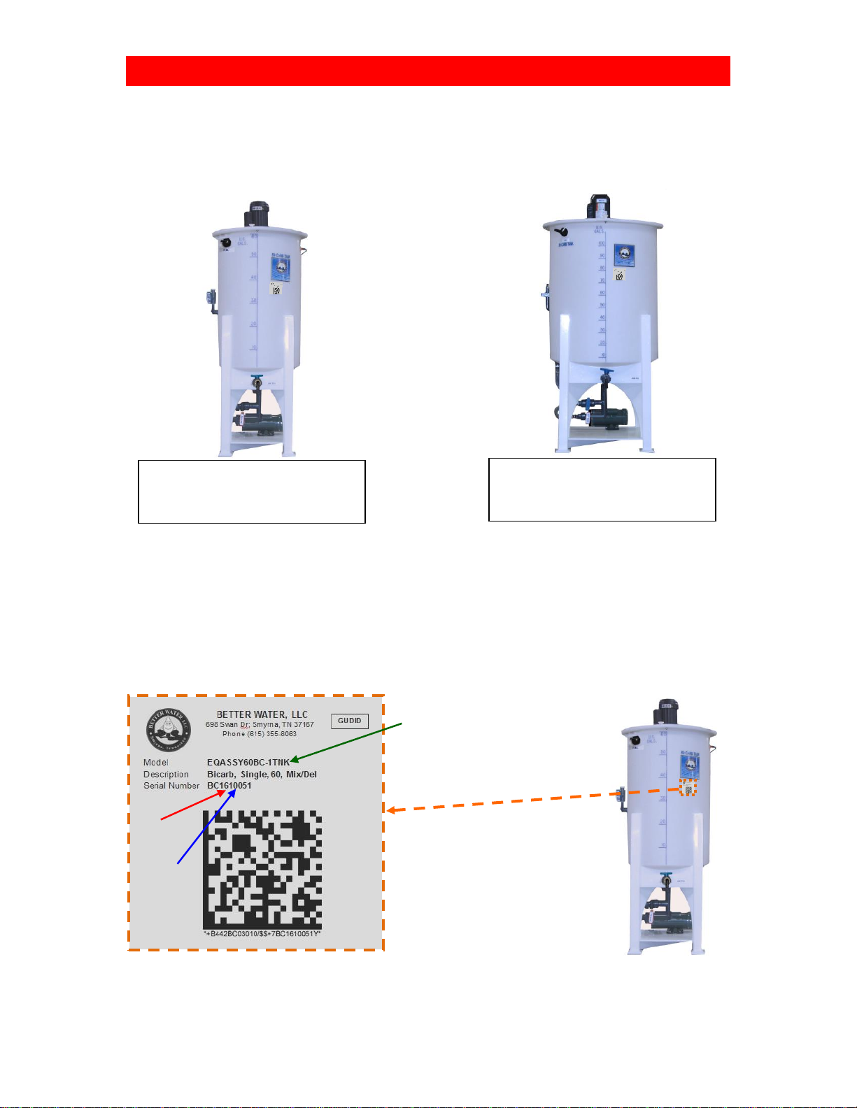
IMPORTANT INFORMATION FOR SUPPORT
Adhered to the front of each Bicarb unit is a label containing important information relating to the
specific Bicarb unit, and details both the Model and Serial Number. Both of these pieces of
information are very important in obtaining support, determining warranty, and properly servicing
the Bicarb unit. Please have this information available if you contact Technical Support.
The first four numbers in the serial number denote the year and month the device was
manufactured. In the example above the Single 60 Gallon Bicarb unit, was produced in 2016, in
the month of October.
Single 60 Gallon Bicarb Unit
Part#
EQASSY60BC-1TNK
Single 100 Gallon Bicarb Unit
Part#
EQASSY100BC-1TNK
“Model”
“16”–Year
“10”-Month
Better Water LLC; rev. Dec 2016
Page 5 of 40
Single Bicarb Tank, Central Mix and Delivery Service Manual
MODEL CHANGES RELEVANT for SUPPORT and
REPLACEMENT PARTS
The following is a summary of changes that were made and the time period they were made in
that are relevant to support and determining the correct replacement part numbers. Refer to the
section above concerning the serial number in determining the year and month the device was
manufactured to determine the relevance of these changes to your device.
January 2005 –Control Box Change
The following changes were made to the Control Box:
- Changed from multiple standard relays to a single smart relay and expansion module
- Changed from a contactor/thermal overload to branch circuit protection
* These changes are detailed in the Control Box-Inside View section below
January 2006 –Float Switch Change
A change was made in the float switches in January 2006. Prior to this a shorter, white float
switch was used, and after a longer, black float switch. The shorter, white float switches are no
longer available, so the float switches described below can be ordered as a replacement. If this
is done, a new bulkhead, through which the float switch is installed, is required. This new
bulkhead must have the inside enlarged to accommodate the area required for full motion of the
longer, black float switches.
* See the Single Bicarb Unit-Front View as well as the Replacing Float Switches sections below.
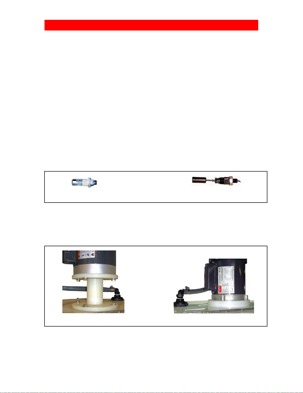
June 2006 –Mixer Motor Mount Change
Prior to June 2006, the mixer motor was mounted on an elongated plastic mount which raised the
motor a few inches above the lid. After June 2006 on, a flat plastic mount was used which
lowered the height of the mixer motor. The mounting hardware also changed to accommodate
the new mount.
* These changes are detailed in the Mixer Motor Mount section below.
Prior to June 2006, Elongated Mount After June 2006, Flat Mount
Prior to January 2006 After January 2006
Shorter, White Float Switch Longer, Black Float Switch
Better Water LLC; rev. Dec 2016
Page 6 of 40
Single Bicarb Tank, Central Mix and Delivery Service Manual
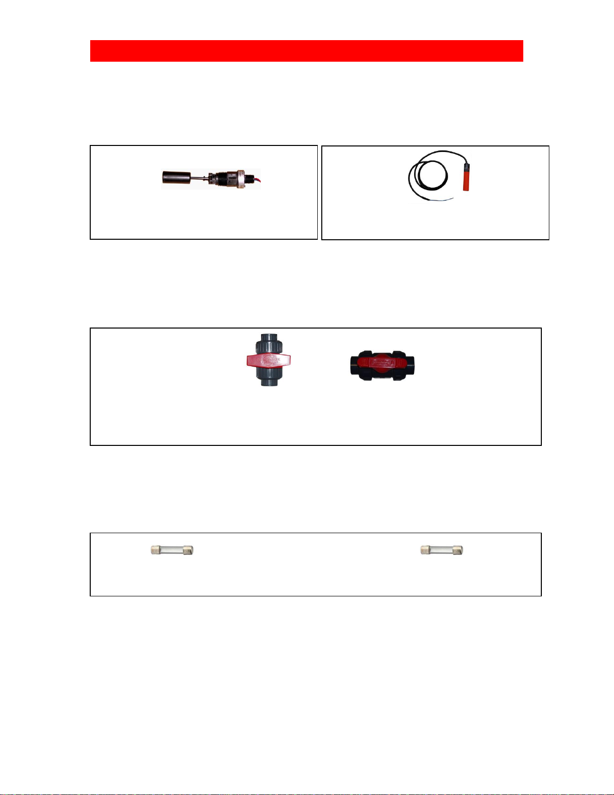
February 2010 –Change from Float Switches to Proximity Sensors
Prior to February 2010, High and Low Level Float Switches were used which are mechanical in
nature. From February 2010 and beyond, electronic sensors were used, and they are not
interchangeable.
* These changes are detailed in the Single Bicarb Unit-Back View as well as the Replacing Float
Switches sections below.
Mid-July 2013 –Ball Valve Change
Units manufactured before mid-July 2013 contained Plast-O-Matic ball valves which were
changed to Asahi ball valves. These valves are not interchangeable. Although their function is
the same, their width and length are slightly different, and the handles are shaped differently.
* These changes are detailed in the Single Bicarb Unit-Front View and Plumbing sections below.
Mid-September 2013 –Fuse Change
The control box fuse was changed from a 3 amp to a 2 amp fuse, and moved from fusing the
secondary side of the transformer to fusing the primary side of the transformer. If the fuse
requires changing, it should be replaced with the same size fuse that the control box was built
with which is specified on the face of the box.
From February 2010
Description part#
High Level Sensor, Tank 1 EQSUBTNK1HL
Low Level Sensor, Tank 1 EQSUBTNK1LL
Prior to February 2010
Description part#
High Level Float Switch, Tank 1 EQSUBBICBTNK1FL
Low Level Float Switch, Tank 1 EQSUBTNK1FL LOW
Description Plast-O-Matic Valve Asahi Valve
1/2" Ball Valve, Red Handle PLVAS800167 PLVAS800167-A
3/4" Ball Valve, Red Handle PLVAS800169 PLVAS800169-A
3/4" Ball Valve, Blue Handle PLVAS800170 PLVAS800170-A
1” Ball Valve, Blue Handle PLVAS800172 PLVAS800172-A
1” Ball Valve, Red Handle PLVAS800174 PLVAS800174-A
ELLFFS00834 ELLFFS00832
Prior to Mid-September 2013 After Mid-September 2013
3 amp fuse 2 amp fuse
Better Water LLC; rev. Dec 2016
Page 7 of 40
Single Bicarb Tank, Central Mix and Delivery Service Manual
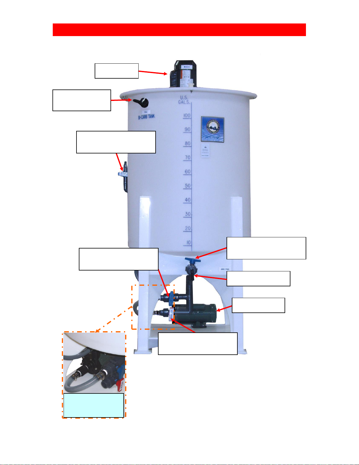
SINGLE BICARB UNIT (FRONT VIEW)
Drain Valve, 1”
Pre-July 2013: PLVAS800174
Post-July 2013: PLVAS800174-A
Distribution Pump
EQPUIW00453
3/4" 90 Poly Nipple (x2)
PLFIPO00351
Mixer Motor
EQBICB01868
Jug Fill Valve, 3/4"
Pre-July 2013: PLVAS800170
Post-July 2013: PLVAS800170-A
Service Valve, 1”
Pre-July 2013: PLVAS800172
Post-July 2013: PLVAS800172-A
Loop Service Valve, 3/4"
Pre-July 2013: PLVAS800170
Post-July 2013: PLVAS800170-A
Close-Up of Pump
And Drain
Connection
90º 1/2" Poly Elbow
MPT x Hose Barb
PLFIPO00355
Better Water LLC; rev. Dec 2016
Page 8 of 40
Single Bicarb Tank, Central Mix and Delivery Service Manual
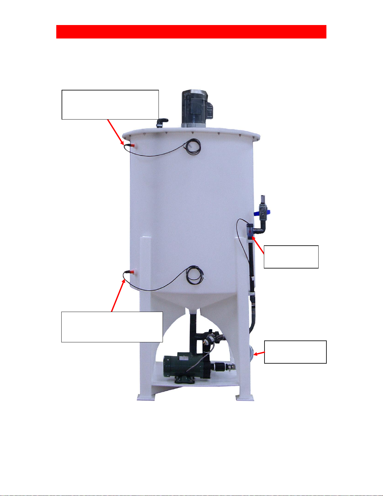
SINGLE BICARB UNIT (BACK VIEW)
High Level Sensor
Pre-2009 (float): EQSUBBICBTNK1FL
2009 (sensor): EQSUBTNK1HL
Low Level Sensor
Pre-2009 (float): EQSUBTNK1FL LOW
2009 (sensor): EQSUBTNK1LL
Flow Switch, 3/4”,
PVC-Clear
PLFSS800443
Clear Suction
Hose, 1FT
PLHOSU01237
Better Water LLC; rev. Dec 2016
Page 9 of 40
Single Bicarb Tank, Central Mix and Delivery Service Manual
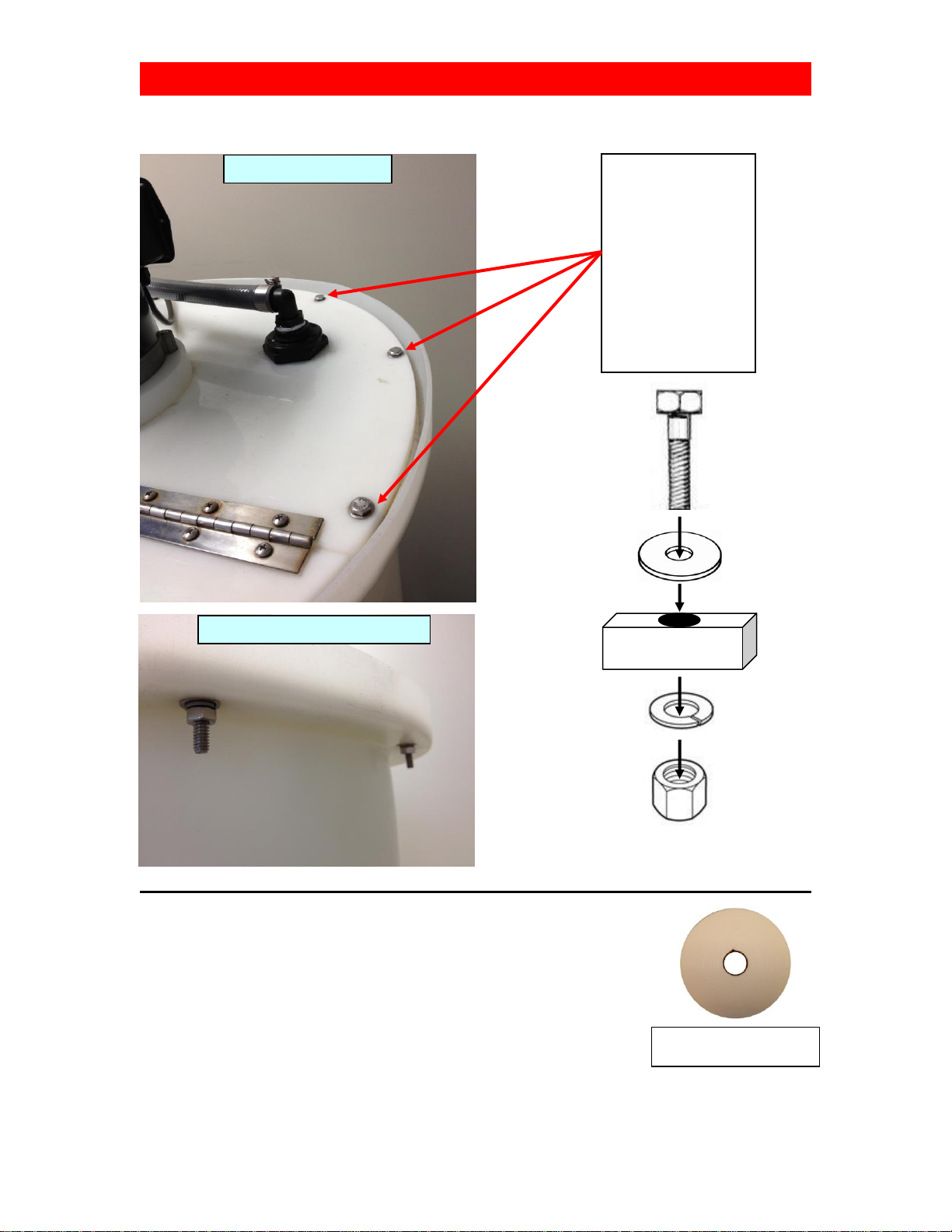
LID & MOUNTING HARDWARE
VOLARA FOAM for Tank Lid
If replacing the Volara Foam (.25” thick x 1.5” width) that helps seal the
lid to the tank, refer to the following:
* 6 ft for 60 gallon Tanks
* 10 ft for 100 gallon Tanks
Mounting Hardware
Kit for 2 Bicarb Lids
<No Part Number>
10 holes per lid,
10 of each
1 3/8” x 1/4" Bolt
1/4" Flat Washer
1/4" Locking Washer
1/4" Nut
LID
Top View of Lid
Underside View of Lid
Volara Foam (.25 x 1.5)
EQBICB01600
Better Water LLC; rev. Dec 2016
Page 10 of 40
Single Bicarb Tank, Central Mix and Delivery Service Manual
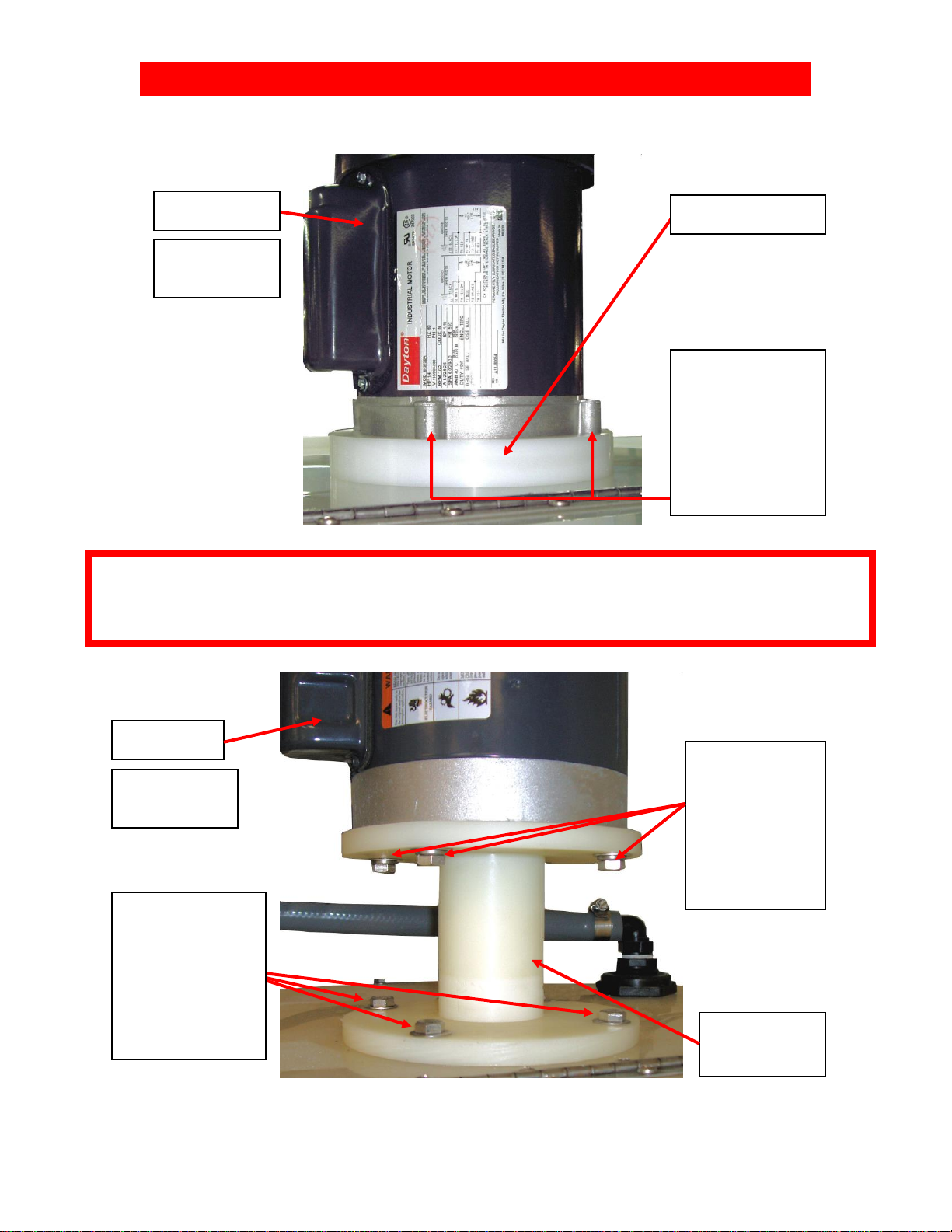
MIXER MOTOR MOUNTS
Mixer Motor
EQBICB01868
Mixer Mount
This style no
longer available
The Mixer Mount / Spacer shown above is included on all Bicarb units produced from June 2006 to
present.
Prior to June 2006, the Mixer Mount shown below was included, but is no longer available.
Mounting Hardware
(4 each)
SS Bolts
HWBOSS01886
SS Lock Washers
HWWASS01913
SS Washers
HWWASS01889
Mixer Motor
EQBICB01868
Mixer Mount / Spacer
EQBICBMXRMNT
Mounting Hardware
(4 each, not shown)
SS Bolts
HWBOSS01892
SS Lock Washers
HWWASS01913
SS Washers
HWWASS01889
Mounting Hardware
(4 each)
SS Bolts
HWBOSS01888
SS Washers
HWWASS01889
SS Nuts (not shown)
HWNUSS01888
Power Cord
(not shown)
ELPCOO00200
Power Cord
(not shown)
ELPCOO00200
Better Water LLC; rev. Dec 2016
Page 11 of 40
Single Bicarb Tank, Central Mix and Delivery Service Manual
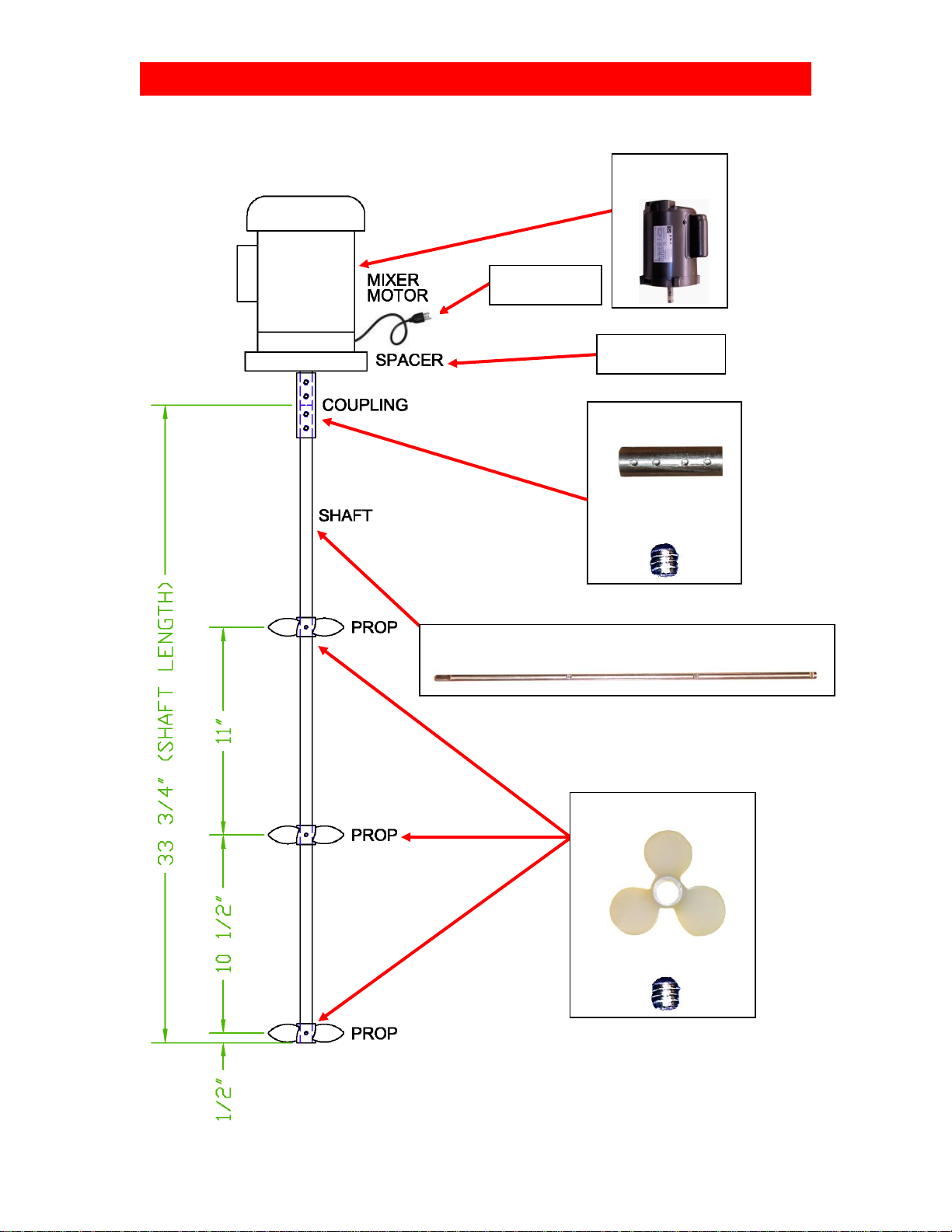
MIXER MOTOR, SHAFT, & PROPELLERS
DIAGRAM
SS Coupling
EQBICB00472
Set Screws (x4)
HWSCSS01920
SS Shaft
EQBICB00471
Mixer Motor
EQBICB01868
Spacer
EQBICBMXRMNT
Poly Pro Props (x3)
EQBICB01923
Set Screws (x3, 1 per prop)
EQBICB01920
Power Cord
ELPCOO00200

Better Water LLC; rev. Dec 2016
Page 12 of 40
Single Bicarb Tank, Central Mix and Delivery Service Manual
REPLACING PROPELLERS, SHAFT and/or COUPLING
1. Unplug the Bicarb unit’s Main Power Cord.
2. Remove the Lid bolts and nuts so the lid can be lifted (not removed).
3. Lift the Lid and remove the bolts and nuts holding the Motor to the Motor Mount.
4. Lift the Motor straight up, to expose the Coupling and Shaft above the Lid, then take a pair of
vice-grips and clamp them to the Shaft below the Coupling. This should allow enough support
and access to proceed.
5. Remove the top two Set Screws in the Coupling, then remove the Motor, carefully laying it on
top of the Tank (sideways).
6. The Coupling can remain attached to the Shaft if neither of these two pieces are being
replaced. If replacing the Shaft or Coupling, then remove the bottom two Set Screws in the
Coupling and set it aside.
7. Lift the Lid and take hold of the Shaft before removing the vice-grips, then remove the Shaft
from the Tank.
8. Remove each Propeller from the Shaft by loosening its related Set Screw. It may be
necessary to use a hammer to gently tap down the Propellers to remove them from the Shaft.
9. Replace each Propeller, aligning the Set Screw with the etched groove, then tighten carefully.
NOTE: Over-tightening can cause the threads on the propeller to strip.
10. Lift the Lid, take hold of the Shaft, and reinsert it back into the Tank, and up through the
Mixing Motor Mount. Hold in place with a pair of vice-grips, leaving enough room above the Shaft
to reattach the Coupling.
11. Reattach the Shaft to the Coupling, then the Motor to the Coupling with the Set Screws. Use
Lock-Tight on each of the Set-Screws before tightening because motor vibration will cause the
set screws to back out which can cause damage to the motor and/or shaft assemblies.
12. Remove the vice-grips and allow the Coupling and Shaft to slip down through the Motor
Mount, back into position.
13. Align and reattach the Motor to the Motor Mount using the previously removed bolts and nuts.
14. Realign the Lid and reattach to the Tank using the previously removed bolts and nuts.
15. Plug the Bicarb unit’s Main Power Cord to an electrical receptacle.

Better Water LLC; rev. Dec 2016
Page 13 of 40
Single Bicarb Tank, Central Mix and Delivery Service Manual
REPLACING a MIXER MOTOR
1. Unplug the Bicarb unit’s Main Power Cord
2. Unplug the Motor’s Power Cord from the Control Box.
3. Remove the old Motor’s Wiring Cover and un-wire the Power Cord.
4. Remove the new Motor’s Wiring Cover and re-install/re-wire the Power Cord, consulting the
wiring diagram on the new motor and wire for low voltage. Replace the Wiring Cover when
finished.
* NOTE: Wire for clock-wise rotation to prevent upward water splash.
5. Remove the Lid bolts and nuts so the lid can be lifted (not removed).
6. Lift the Lid and remove the bolts and nuts holding the Motor to the Motor Mount.
7. Lift the Motor straight up, to expose the Coupling and Shaft above the Lid, then take a pair of
vice-grips and clamp them to the Shaft below the Coupling. This should allow enough support
and access to proceed.
8. Remove the top two Set Screws in the Coupling, then remove the Motor, carefully laying it on
top of the Tank (sideways).
9. Attach the new Motor to the Coupling, with the Set Screws. Use Lock-Tight on each of the Set-
Screws before tightening because motor vibration will cause the set screws to back out which can
cause damage to the motor and/or shaft assemblies.
10. Remove the vice-grips and allow the Coupling and Shaft to slip down through the Motor
Mount, back into position.
11. Align and reattach the Motor to the Motor Mount using the previously removed bolts and nuts.
12. Realign the Lid and reattach to the Tank using the previously removed bolts and nuts.
13. Plug the Motor’s Power Cord into the Control Box.
14. Plug the Bicarb unit’s Main Power Cord into an electrical receptacle.
1/4" HP Mixer Motor Bicarb Power Cord
EQBICB01868 ELPCOO00200
Better Water LLC; rev. Dec 2016
Page 14 of 40
Single Bicarb Tank, Central Mix and Delivery Service Manual
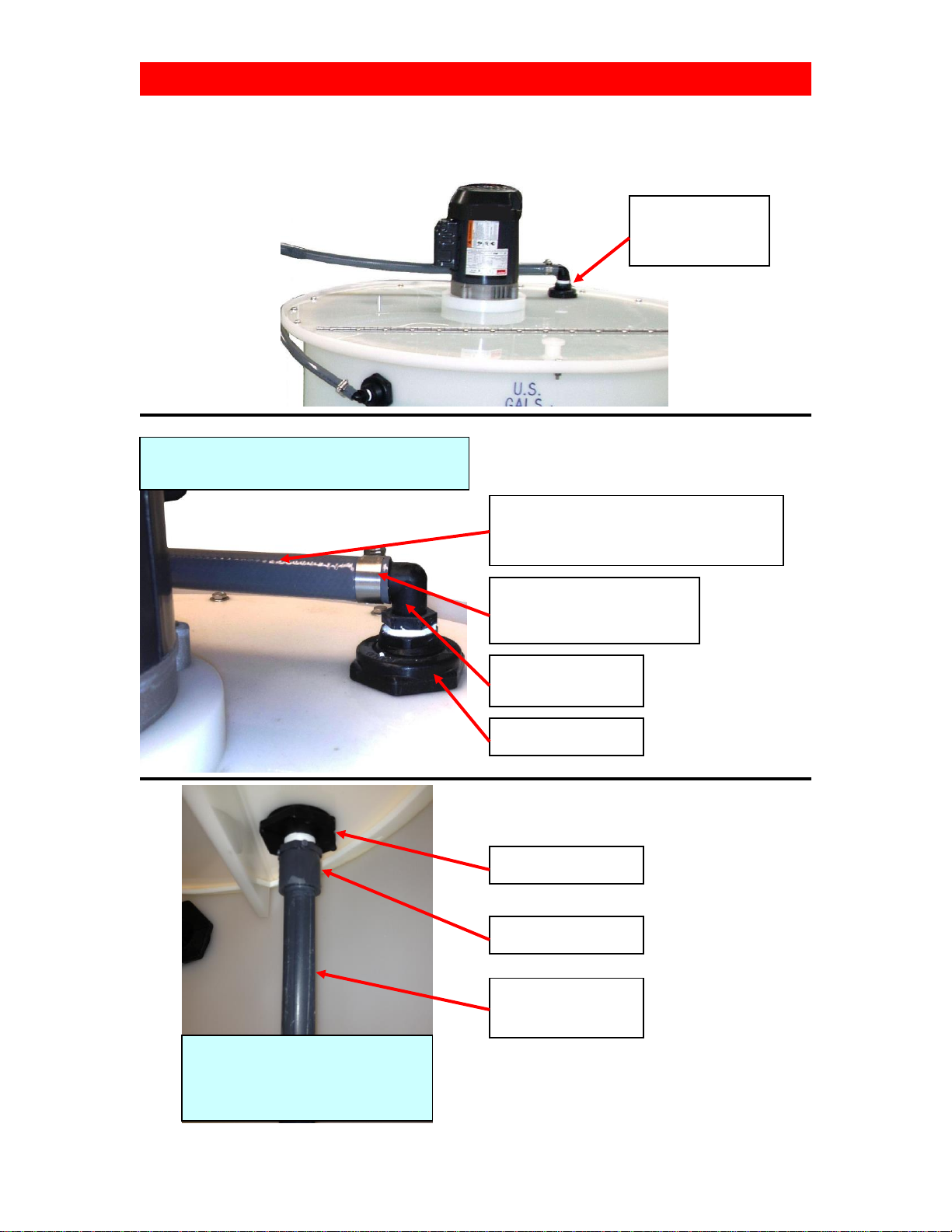
RETURN-to-TANK FITTINGS / DROP-DOWN TUBE
Top View of Lid
Showing Hose, Clamp, & Bulkhead
Underside of Lid
Inside Tank View
Showing Bulkhead, Adapter,
and Drop-Down Tube
90º 3/4" Poly Elbow
MPT x Hose Barb
PLFIPO00351
Clamp Lined
Worm-Drive Hose
(x2, one for each end of hose)
PLHOCL002
3/4" Poly Bulkhead
PLFIPO00308
3/4” Hose Style 5000
Length from tank to header
PLHOST00315
3/4" Poly Bulkhead
PLFIPO00308
S8 Male Adapter SxT
PLFIS800098
3/4" Sch 80 Pipe
(32” length)
PLPIS800044
Return-to-Tank
Fitting
(Drop Down Tube
inside tank)

Better Water LLC; rev. Dec 2016
Page 15 of 40
Single Bicarb Tank, Central Mix and Delivery Service Manual
FILL INLET CONNECTIONS
- OR -
Close-Up of Tank
Showing Hose, Clamp, & Bulkhead
90º 1/2" Poly Elbow
MPT x Hose Barb
PLFIPO00355
Inside the Tank Connection to the Bulkhead can be one of two configurations both of
which are shipped with the Bicarb unit in the Accessories Box
90º 1/2" Poly Elbow Flow Control, 2.0 GPM
MPT x Hose Barb +PVC Sch-80
PLFIPO02070 PLFCS802001
90º 1/2" Poly Elbow
MPT x Hose Barb
PLFIPO00355
Clamp Lined
Worm-Drive Hose
PLHOCL001
1/2” Hose Style 5000
(60 gallon –19”)
(100 gallon –25”)
PLHOST00322
1/2" Poly Bulkhead
PLFIPO01848

Better Water LLC; rev. Dec 2016
Page 16 of 40
Single Bicarb Tank, Central Mix and Delivery Service Manual
VERIFYING FLOAT SWITCH FUNCTIONALITY
Float Switches were used on Bicarb units produced prior to February 2010. Bicarb units
produced from February 2010 use the High and Low Level Sensors.
When a Float Switch is suspected of poor functionality or failure, this test should be performed.
This is the same test performed at the Better Water manufacturing facility on returned Float
Switches to verify warranty claims.
1. Obtain a two-lead multi-meter and place in continuity mode.
2. Attach the multi-meter leads to the contacts on the Float Switch wire.
* NOTE: The wire colors are different between the High Level and Low Level Float Switches.
3. Cycle the Float between open and close by raising and lowering the Float.
4. Take note as to whether the multi-meter alarms with the action of the Float reliably.
- The multi-meter should steady alarm when the Float is in the closed position.
* HIGH LEVEL FLOAT SWITCH: alarms on the multi-meter when in the UP position
* LOW LEVEL FLOAT SWITCH: alarms on the multi-meter when in the DOWN position
HIGH LEVEL FLOAT SWITCH
EQSUBBICBTNK1FL
Alarms on the multi-meter when in the UP
position
Attach multi-meter
leads to the Float
Switch wire connection
holes here
LOW LEVEL FLOAT SWITCH
EQSUBTNK1FL LOW
Alarms on the multi-meter when in the
DOWN position
A failure to steady alarm in the closed position is the determination of a
defective Float Switch.
This manual suits for next models
1
Table of contents
Other Better Water Water Filtration System manuals


Popular Water Filtration System manuals by other brands

Antunes
Antunes UFL-410 Series owner's manual

JRC
JRC NSVA300 manual

Reven
Reven X-CYCLONE Operating and maintenance instructions

TeichTip
TeichTip SUNSUN CPF-50000 Operation manual

Beko
Beko OWAMAT 2 Instructions for installation and operation

amiad
amiad Filtomat M100 Installation, operation and maintenance instructions


