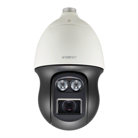
bettini SD-373C User manual

1
SPEED DOME CAMERA
User Manual
Model
SD-373W: Outdoor with wall bracket
SD-373C: Pendant Outdoor
SD-373D: Ceiling Indoor

2
Contents
Safety
3 Safety Regulations
6 Precautions
Product Overview
7 Features 44 Day & Night
8 Components 45 Others
10 Product Configuration 46 Sequence Settings
Installation and Connection
46
50
Preset Settings
Scan
11 Connecting Camera Communication Board 51 Group SEQ
14 ID & 485/422 Communication DIP Switch Settings 52 Pattern
15 Camera ID DIP Switch Settings 53 Auto Run
16 485/422 Communication DIP Switch Settings 54 Power Resume & MD Dwell Time
16 Termination/
Communication Method/Communication
Response Settings
55
P/T
17 Baud Rate/Protocol Settings 55 Position Limit
18
21
WTX-1200 Keyboard Instruction
Connecting Power Adapter & Cable
56
58
Speed Limit
Prop. P/T
22 Assembly & Installation 59 Text Area
60 Masking
Settings 61 Image Hold
32 Symbols used in the Product 62 OSD Settings
33 Supplying Power 64 Alarm Input
34 OSD Command/ Function Chart & Menu Controls 65 Alarm / Aux. Output
35 OSD Menu Chart 67 Initialize
36
36
Camera Settings
Focus & Zoom Settings
68
Status Settings
37 Zoom Tracking
38 White Balance Settings Trouble Shooting
39 Exposure Settings
69
Trouble Shooting
40 Back Light Settings
42 AGC (Auto Gain Control) Settings Product Specification
43 SSDR (Samsung Super Dynamic Range) 72 Specifications
74 Dimensions

3
Safety
Safety Regulations
The purpose of the Safety Regulations is to prevent the risk of damage to property and user’s health.
Please read the following precautions carefully.
Detailed Safety standards are as follows:
Warning Failure may result in death or serious injury.
Caution Failure may result in personal injury or property damage.
INFO Indicates detailed specification of the product. Please read this part to understand detailed menu.
Please read the manual and use the product in accordance with the instructions.
Please heed all warnings
Power
Warning
When connecting the power supply, check the external connection terminal.
- Incorrectly connecting power supply may cause fire, electric shock, or product failure.
Stop using the product, when there is smoke or strange smell.
- In such case, immediately disconnect the power source and contact the service center.
Continued use may cause fire or electric shock.
Unplug the power supply, when there is a lightning, and storm
- This may cause a fire or product failure.
Caution Firmly connect the power cord to the power connector before use.
- A loose connection may cause a fire.
Installation
Warning
Must use the adapter that is provided when you purchased our product.
- Using other adapters may cause fire, electric shock, or product failure.
Caution
When installing the camera on a wall or ceiling, fasten it securely and firmly.
- The camera may fall and cause serious damage.
Do not place conductive objects or water containers on top of the camera.
- May cause fire, electric shock, or injury.
Do not connect multiple cameras to a single adapter.
- Exceeding the capacity may cause abnormal heat or fire.
Personal construction is prohibited.
-
The construction requires experience and technic; contact your dealer for construction.
Personal construction may have danger of fire or electric shock.
Do not insert any foreign objects or decompose the product.
- May cause product failure or fire.
Do not install the product where the product can be exposed to radiation.
- Radiation exposure may cause damage to the product.

4
Cleaning
Note
Do not directly spray the water onto any parts of the product.
-May cause fire or electric shock.
Gently wipe the surface with a dry cloth.
-Never use chemical substances or detergents, using them will damage the painted surface.
Note
Do not install the product in places where there is a lot of moisture, dust or soot.
- May cause fire, or electric shock.
Do not drop any objects on the product or apply strong impact.
- Keep away from excessive vibration or strong magnetic influence.
Do not install in a location where temperature is too high (55℃or higher) or low
temperature (-40℃or below) or high humidity.
- May be a cause of fire, or electric shock.
Keep away from heat vents or heating appliances.
- May be a cause of fire, or electric shock.
If you want to relocate already installed product, be sure to turn off the power
before moving or reinstalling.
- May cause a fire or electric shock.
Install at well-ventilated locations.
-May cause a fire or electric shock.

5
FCC Statement
This equipment complies with Part 15 of the FCC Rules and operates in accordance with two terms below.
(1) This equipment may not cause harmful interference.
(2) This equipment accepts any interference received, including interference that may cause undesired
operations.
CAUTION
This equipment has been tested and certified against the limits for a Class A Digital Device Regulations in
compliance with the provision of Part 15 of FCC Rules. These limitations are designed to provide reasonable
protection against harmful interference from the equipment installed in a residential area. This equipment
generates and uses radio frequency energy and able to release radio frequency energy, therefore, installing
this equipment not in accordance with the instruction manual may cause harmful interference to radio
communications.
However, in special cases, there may be interference even though the equipment has been properly installed.
IC Compliance Notice
This Class A digital equipment meets all the requirements of the Canadian Interference-Causing
equipment Regulations regarding equipment that may cause interference.
The Proper disposal of the product (Electrical, electronic equipment disposal classification)
Means that this product should not be disposed together with other house hold wastes. Therefore,
this equipment should be disposed at a designated collection point for recycling or disposing
electrical and electronic wastes. Properly disposing and recycling electrical, electronic wastes will
protect your health and the environment, and conserves natural resources. Contact your local city
office, the waste disposal company, or the shop where you purchased the product for detailed
disposal or recycling locations.
CAUTION
Only qualified service personnel can use all the service instructions. In order to reduce danger of electric
shock, or other hazards, services that are not included in the operating instructions may by prohibited.

6
Precautions
1. This product must be installed in the vertical direction. Please do not install the product upside down or
other directions
2. Please use strong safety chain while installing the product in order to avoid a hazard such as product falling.
3. When using a wall mount, ensure sufficient strength of the screw to prevent the product from falling.
4. Take extra care while moving the product to prevent damage to the product.
5. When connecting power, communication, video and IR lamp through cable gland, seal with tape to prevent
infiltration of water.
6. Please turn off the product when opening the housing in order to install the product.
7. Always use rated adapter.
8. Please use the power adapter that has greater power capacity that 24V AC, 2.5A (UL Listed Class 2 Adapter)

7
Product Overview
Features
Various Protocols and Coaxial Communication
RS-422/485 communication and Coaxial(Pelco-C) communication is provided.
- RS-422/485: SAMSUNG-T, SAMSUNG-E, Pelco-D, Pelco-P, Panasonic, Honeywell, AD, Vicon, GE, Bosch,
CyberScan, Bandi, Dongyang, Camtron
-Coaxial Communication: Pelco Coaxitron (Auto Detection)
Wide Range Auto Security Functions
-Preset Storage Mode : Up to 255 PRESET setup is available, and independent Scene data setup for each
PRESET realizes optimal video.
-Image Holding : Preset Freeze function reduces the eye fatigue of the user during Group operation.
-PTZ Pattern : Joy-Stick manipulation pattern command can be saved and replayed.
-Scan : The swing function enables camera to move between 2 select locations and monitor the path.
-Group Search : up to 319 preset positions can be monitored in order.
Masking
If a monitoring location includes a highly private area, the area can be selectively masked on the screen.
Proportional P/T(Main->P/T->Speed Limit-> Prop. P/T)
The Proportional P/T function automatically adjusts the control speed of the Pan and Tilt functions
according to the current zoom ratio. It is useful to adjust the functions manually for detailed controls when
monitoring at high zoom ratios.
Day & Night
With its daytime & nighttime switch and Sens-Up functions based on the ICR (Infrared Cut filter Removal),
the camera provides high quality pictures regardless of whether it is day or night.
- Sens-Up increases the CCD sensitivity by electrically extending the camera’s exposure time.
- Day & Night enables you to select between color and B/W modes depending on the lighting conditions.
OSD(On Screen Display)
The camera IDs, camera preset numbers, preset names, area names, and camera operation status are
displayed on the monitor, allowing set up of various camera functions through the OSD menu screen.
High Strength All-in-one Type(Outdoor Type)
IP66 level all-in-one housing type enables fast and easy installation, and fully protects from the external
environment. The built-in high performance Heater, and Fan enables the camera to perform under -50°C ~
50°C conditions.
Digital Flip
This function is useful to monitor the subject which passes right beneath the camera. When the subject
passes right beneath the camera the Tilt Angle tracks the subject more than 90 degrees to the opposite side
without Pan action. And digitally calibrate the screen inversion which occurs when the Tilt angle passes 90°.
Model Specification
SD-373D: Indoor type 37X Zoom Lens, SD-373W – SD-373C: Outdoor type 37X Zoom Lens

8
Components
SD373-D
SD373-D Optional Adapter (AC 24V, 2.5A) User Manual Quick Manual
Install Base Screw Anti-theft Screw L-Wrench
(2.5)
SD373W – SD373-C
SD373-W/C Optional Adapter (AC 24V, 2.5A) User Manual Quick Manual

9
Mounts (Optional)
The following items are optional and sold separately.
:
Wall Mount Ceiling Mount
Corner Mount In-Ceiling Housing

10
Product Configuration
[SD373-D] [SD373W/C]
❶Camera Module & Dome Cover
❷Main Housing
❸Install Base
1
2
3

11
Installation & Connection
Connecting Camera Communication Board(Interface Board)
Refer to the image below for product wiring.
(Coaxial communication method does not require additional control signal wiring)
❶Main Power Connector
❷Video Output Connector
❸485/422 Communication Connector
❹Alarm Input Connector (1ch ~ 6ch)
❺Alarm Output Connector (1ch ~ 2ch)
1
2
3
4
5

12
Supplying Power
The power adapter does not have polarity.
- The maximum capacity is 24V 2.5A.
- Incorrectly connecting the power and GND to NC/NO port will cause
short circuit and may cause fire or damage the product.
Connecting Communication
RS-485 Communication
SD373 Controller or DVR
RS-422 Communication
SD373 Controller or DVR
For more precise text information, refer to the silk screen text of the board.

13
Connecting Alarm
<Alarm Input ConnectorJ5><Alarm Output Connector J10>
Name Descriptions Name Descriptions
IN1 Alarm Signal Input 1 1N.C Normal Close 1
IN2 Alarm Signal Input 2 COM1 Common 1
IN3 Alarm Signal Input 3 1N.O Normal Open 1
GND Ground 2N.C Normal Close 2
IN4 Alarm Signal Input 4 COM2 Common 2
IN5 Alarm Signal Input 5 2N.O Normal Open 2
IN6 Alarm Signal Input 6
GND Ground
Alarm Output
Connector J10
Alarm Input
Connector J5

14
ID & 485/422 Communication DIP Switch Settings
❶Disassemble the camera body from the Install Base, and place the camera to face the bottom as shown in the
picture below.
❷Setup ID and 485/422 communication environment through DIP SWITCH.
❸If the switch is no completely On/Off, the product may not work properly, therefore, check again after the
setup.
Coaxial Communication Method (Pelco-C) automatically detects the signal, therefore, there will not be additional
communication setup needed. And it can be used through every compatible controller.
DIP SWITCH Purpose
S1 ID Setup
S2 Termination Resistor, 422/485, RESPONSE, BAUDRATE, Protocol Settings
S2
S1

15
Camera ID DIP Switch Settings
Assign a unique number for each camera.
The initial value of the switch is “0”, and all 8 switches are set to OFF as default.
Each switch has a unique value, and the ID is the sum of the values.
S1-DIP 1 2 3 4 5 6 7 8
Value 1 2 4 8 16 32 64 128
Example of Camera ID Settings (On: Off: )
Example 1 Example 2 Example 3
0+0 = 0 (ID = 1*) 2+4 = 6 (ID = 6) 1+2+4+8+16+32+128
=191 (ID = 191)
Use a unique ID for each Camera.
If the summation value is “0”, it is recognized to ID as “1”.
S1
S1

16
485/422 Communication DIP Switch Settings
Termination Settings
In order to prevent the attenuation of the communication signal between camera and controller, need to have
termination setting for camera that is farthest from the camera/controller communication loop.
Terminal Resister S2-1 S2-2
ON OFF ON OFF
RS-422 RX, RS-485 Terminated Not Terminated -- --
RS-422 TX -- -- Terminated Not Terminated
Communication Method Settings
Select a communication method for the camera.
Function ON OFF
S2-3 Communication Mode Switch RS-422(4Wire) RS-485(2Wire)
Communication Response Settings
Select a communication response method for the camera.
Function ON OFF
S2-4 Response Switch Response No Response
S2

17
Baud Rate Settings
Select a transfer speed of a selected communication protocol.
No Baud Rate(BPS) S2-5 S2-6
1 19200 ON ON
2 4,800 ON OFF
3 9,600 (Default) OFF OFF
4 2400 OFF ON
In order to use the third party controller, please contact the manufacturer or our Sales Department.
The product’s DIP switch is set to OFF as default, and the values in the shadowed are in the table above will
be provided as a default.
Protocol Settings
Select a Protocol for the camera.
No Protocol S2-7 S2-8 S2-9 S2-10
0
Major Automatic
OFF OFF OFF OFF
1
Pelco-D,P
OFF OFF OFF ON
2
SAMSUNG-T
OFF OFF ON
OFF
3
SAMSUNG-E
OFF OFF ON
ON
4
Panasonic
OFF ON
OFF OFF
5
Vicon
OFF ON
OFF ON
6
Honeywell
OFF ON
ON
OFF
7
AD
OFF ON
ON
ON
8
GE
ON
OFF OFF OFF
9
BOSCH ON
OFF OFF ON
10 DONGYANG ON OFF ON OFF
11 CYBERSCAN ON OFF ON ON
12 Reserved ON
ON OFF OFF
13 Reserved ON
ON OFF ON
14 Reserved ON ON ON OFF
15 All Automatic ON ON ON ON
Major Automatic: PELCO-D, PELCO-P, SAMSUNG-T, SAMSUNG-E, PANASONIC. These protocols are
automatically recognized. Other protocols will not be automatically recognized.
All Automatic: All the protocols are automatically recognized. (Parallel connection of more than 3
cameras is not recommended.)
Camtron Protocol & Pelco-C (Coaxitron) works for every protocol.

18
WTX-1200 Keyboard Instruction
Features
1~255 Camera Control
Supports Multi-Protocol
RS-485/422 Communication
Supports User Password
Supports PRESET, Group, Scan, and Pattern Motion
Product Configuration
Number Button Description
1 ESC/POWER Power on/off function and escape key
Press down the button for 2~3sec to Power off.
2 LCD DISPLAY Camera ID, Protocol, baud rate, Etc. will be displayed
3 Numbers ID or PRESET number can be saved and played
4 Controller Function
Keys
HOLD : System locking (Unlocking : 4-digit password)
AUX : Aux 1-Wiper on/off
Aux 2-Light on/off
SET : PTZ (1+SET), MAIN (2+SET)
OPEN : OSD menu enter
CLOSE : OSD menu escape
5 Function Keys F1 : Preset, F2 : Group, F3 : Pattern, F4 : Scan, MENU : OSD menu
6 Zoom/Focus Camera Focus & Zoom Control
7 Mouse Not included

19
Number Item Description
1 Joystick Controls Pan, Tilt, and Zoom
2 DC 12 Input DC 12V / 140mV
3 USB Port USB Port for external communication
4 TRx Tx3 Tx2 Tx1 RS-485/422 Communication Terminal
5 Program Download connector for Program update
Controller Function Settings
Preset(F1 Button)
Assigning a PRESET: Number Button + F1 Button (for 2~3sec)
Executing the PRESET: Number Button + F1 Button
Group(F2 Button)
Executing the Group: Number Button + F2 Button
Pattern(F3 Button)
Assigning a Patter: Number Button + F3 Button (for 2~3sec)
※Press MENU Button to complete the Patter settings.
Executing the Pattern: Number Button + F3 Button
Scan(F4 Button)
Executing the Scan: Number Button + F4 Button

20
Aux(Wiper & Light)
Wiper on : 1 + AUX Button
Wiper off : 1 + AUX Button (for 2~3 sec)
Light on : 2 + AUX Button
Light off : 2 + AUX Button (for 2~3 sec)
※Execute the Preset Number to implement corresponding functions
Protocol Preset Number Description
PELCO-D/P
92 Camera menu open
95 Camera menu open
62~65 Run Scan 1~4
66 Run Preset Status
67 Run Auto Pan
71 Run DIS
72~77 Run Group 1~6
81 Run Pattern
82~85 Run Pattern 1~4
86, 88 Aux 1 ON
70, 90 Aux 1 OFF
87, 89 Aux 2 ON
80, 100 Aux 2 OFF
92 Run Home Position
93 Run Freeze
95 Run Day & Night
96 Run Home Position
This manual suits for next models
2
Table of contents
Other bettini Security Camera manuals
Popular Security Camera manuals by other brands
Digital Watchdog
Digital Watchdog PTZ39X user manual
Lorex
Lorex LNB2153 SERIES quick start guide
DELTA GROUP
DELTA GROUP Vivotek SUPREME SD9368-EHL user manual
Vimar
Vimar ELVOX 46822.036C user manual
Samsung
Samsung SCP-2370RH user manual
Costar Video Systems
Costar Video Systems CCI2143HSB Quick installation guide


