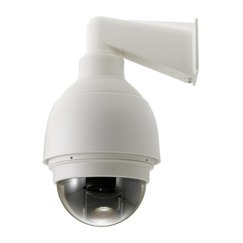
bettini EN-9230AUT User manual

IR HIGH SPEED DOME CAMERA
EN-9230AUT / EN-9237AUT
USER’S MANUAL V3.0

1
Table of Contents
Precautions………………………………………………………………....2
Features……………………………………………………………………….4
Technical Data……………………………………………………………..9
Installation Guide…………………………………………………………10
Dome Settings…………………………………………………………..…16
Operation Instructions…………………………………………………20

2
1 Precaution
1. Please read this manual carefully before the installations and operations.
2. Transportation Security
No heavy stress, violent vibration or water splash are allowed during
transportation, storage. The unit should be transported in separated
packing. In shipments of distributor and delivery of maintenance, any
damages caused by integral packing are not covered by warranty.
3. Installation
Avoid heavy stress and violent vibration during installation. Don’t touch the
dome cover directly by hand. When connecting the power source, please
follow all electric safety standards and only use the power supply
designated for this device. Keep the video and control signal in a decent
distance from high voltage devices and cable. Don’t apply power to dome
before finishing the installation.
4. Internal Environment
Keep metal and inflammable material away from dome body to avoid fire
short circuit and damage. Please prevent all liquids material from entering
the dome. If this occurs, please shut down the power and pull out the
plug-in. Then please inform the technical personnel immediately.
5. Electrical Safety
The video image would be interfered when the dome is installed near
Television, radio transmitter, voltage changer and audio amplifier.

3
6. Camera Protection
Avoid shooting very bright objects directly into the camera’s CCD (such as
the sun or light fittings) and avoid fixating the camera lens on bright static
object for long time, as it will cause Irreparable damage to the camera’s
CCD.
7. Cleaning Method
Please don’t use abrasive and violent detergent to clean the dome. Please
choose dry fabric and neutral detergent. And please use lens paper to clean
the lens.
8. Internal removing, assembly, repair and operations should be only
performed by qualified service personnel.
9. Please use our production under the following environmental standards:
Environmental Temperature
-35
~
60oC
Environmental Humidity <95%
Barometric Pressure 86~106KPa
Power Supply
DC12V/4A

4
2 Features
2.1 Main Features
• Stepless speed changes, auto zoom/speed matching
• Pan 0.01~360o/S, Tilt 0.01o~120o/S, Preset: 360o/S
• Auto object track with zoom in/out and motion detection
•Timing actions for 7 days of programmable schedule
• Built-in Semi-conductor heater & digital temperature sensor
• PWM cooling fan vari-speed temperature control
• Pan Tilt accuracy +/- 0.1o, 220 preset positions
• 8 cruising tracks, each cruising track has 32 presets
• 4 Pattern Tours, 10 Mins memory, 500 programmable instructions
• Multi-Protocol through RS485
• 8 auto scan with use-defined left and right boundaries and settable scan speed
• 8 Privacy Zones with defined English camera title
• Auto Compatible PELCO_P, PELCO_D
• Guard Location: the dome will rotate back to preset position after a period of
vacant time
• Alarm triggering: the alarm can trigger preset, auto scan, cruising and pattern
tours functions
•Soft Address Function: the use can set up the dome address without uninstall
the dome

5
2.2 Integrated Super Speed PTZ Rotator
• Delicate stepping motor, stable, sensitive and accurate
• 360° Pan and 90° Tilt range (auto-flip) without blind area
• Stepless speed change, auto zoom/speed matching
•Near / far IR Light auto matches camera zoom in/out
2.3 Built-in High Definition Day/Night Camera
• Auto iris, auto back light compensation
• Auto/manual white balance
• Auto/manual brightness control
• Auto/manual focus
2.4 All-weather Outdoor Design
•6 Inch High die-cast alloy aluminum construction
• High Precision Mould with high heat conductivity
• Fully enclosed isolation design for heat sink
• Nanometer Dustproof, waterproof and fog-proof lens
•IP66 Waterproof
•3000V lightning and surge current protection
2.5 Function Instructions
•Focus / PTZ Speed Auto Match
The pan/tilt rotation speed could be automatically adjusted according to the
focus in/out, which makes it much more practical for manual target tracking.
(Only for the auto tracking IR speed dome)

6
•Auto Flip
When the camera tilts downward and goes just beyond the vertical position, the
camera will rotate 180 degrees.
•Preset Position Set up and Call Up
In the Preset function the dome stores the current pan/tilt angle, zoom and
other position parameters in its memory. When necessary the dome recalls
these parameters and adjusts the camera to a particular position. The user can
store, recall and clear the presets easily and promptly by using the keyboard
controller. The dome can store up to 220 presets.
•Auto Scan
Users can set up the left and right boundaries by control keyboard. Then speed
dome can scan between this boundary. It supports up to 8 groups of scanning
paths.
•Cruising Track
The preset position can be programmed to be recalled in a set of sequences. This
sequence can be set to let the camera scan from one position to the next in a
cycle at a set speed. This feature is called the “auto cruise”. The cruise sequence
and dwell time of each preset can be set. It supports up to 8 cruising tracks, each
cruising track with 32 presets.
•Pattern Tour
Dome can memorize 600s running path or 500 programmable instructions.
When start pattern tour, speed dome will move automatically according
recorded action path. It supports 4 groups of pattern tours.
•Guard Location
The dome will automatically return to preset position if there is no operation in a
period of vacant time.

7
•Default Action
When you start up the dome camera or do not send commands over a long time,
the dome camera will return to its default functions which include the home
place, auto pan, auto cruise and pattern.
•Dome Address Setup
The dome supports up to 256 addresses and the dome will only response to the
instructions given to its own address. Please check the dip switch on the bottom
of the dome for address setup.
•Manual Object Tracking
The use can move the joystick up, down, left or right to track the appearing
object in the screen and use the joystick to zoom in and out with auto focus.
•Privacy Mask Protection
Set black mask areas to protect the privacy zones. The black privacy locations
can be set, and support up to 8 mask zones.
•Timing Running Function
Users can set speed dome operation task at total 8 timing areas during 7 days.
• Coordinates and Directions Display
User can define the dome’s direction of due north, which will help to show up
the exact moving directions on screen. And zone title is supported to display
when the dome moves to the specified zone.
•Auto Tracking
The dome will automatically fix and track the moving object according to the
user’s setup via OSD.
•Motion Detection
The dome will detect the changes in the defined video zone and trigger alarm. It
supports to 8 video Locations, each with 4 detection zones.

8
•PTZ and Lens Control
1) Zoom Control
Users can control zoom by keyboard to get near or far images.
2) Focus Control
The default setting is auto focus. The camera will auto focus based on the center
of the video display to get the clear image. In some special occasions, the user
could do the manual focus to get the desired image effect.
3) Auto Iris Control
Auto Iris is aiming to detect the environmental lights condition and adjust the iris
to get the stabilized brightness of the image.
4) Auto Back Light Compensation
In the highly bright background, auto back light compensation is aiming to
compensate the brightness of the dark object and adjust the background
brightness to get a clear image.
5) Auto/Manual White Balance
Auto/Manual WB adjust depending on the environment light changes.
6) Day and Night Switch (Only for Day/Nigh Camera)
Speed dome camera can auto switch according to the environmental
illumination changes.
7) OSD Setup (Only for camera with menu)
Call upon preset No.95 to enter into OSD menu setup interface. Press “Focus” to
choose menu items and press “Iris” to set menu contents.

9
3 Technical Specifications
Power Supply DC12V+10% 60W
Night IR Distance 120/150 meters max.
Manual Speed Pan 0.01o~360o, Tilt 0.01o~120o
Preset Speed 360 o/S
Pan Angle 360o continuous pan rotation
Tilt Angle -10°~90o (Auto Flip)
Presets Positions 220
Preset Accuracy +/-0.1o
Auto Scan 8 auto scan tracks, user-defined left and right boundaries and scan speed
Auto Cruising
8 cruising tracks, each cruising tracks has 32 preset positions,
user-defined dwell time
Pattern Tour 4 groups, each one with 10 Mins memory, 500 programmable instructions
Guard Location The dome will rotate back to preset position after a period of vacant time.
IR LED On Mode Manual/Auto/Timing
Data
Communication
RS-485
Protocols Auto Compatible PELCO/P, PELCO/D
Baud Rate 2400/4800/9600bps
Operating Humidity 0~90%
Operating Temp -35o~+60oC

10
4 Installation Guide
4.1 Preparations
1) Basic Requirements
All the electric work must be finished under the latest electric & fire prevention
law and rules (and any related law and rules). Please check according to the
packing list if every accessory is included. And also make sure the installation is
operated as required. Please contact us for any help during the installation.
2) Installation Space and Density Checkup
Please make sure the space is big enough to install our dome. And also ensure
the density of the ceilings or walls to hold total weight of the dome and its
accessories.
3) Cables Preparation
Please choose the proper cable according to the transmission distance. The min
requirement of
coaxial BNC cable
is listed as follows
for reference:
4) Setup Dip Switch for Dome Address
*Please turn to Part 5 for details.
Models
Max Distance
(
Feet\Meter
)
RG59/U
229m
RG6//U
305m
R G 1 1/ U
457m

11
4.2 Installation Method and Dimensions
The IR speed dome could be installed in wall-mount and pedant-mount

12
4.4 Installation Procedures
*Notice: The wall and ceiling must be thick enough to install the expansion bolts
and can bear 4 times the weight of the dome camera itself.
Wall-mount Installation Procedures:
1) Take out the bracket from the package (as shown), mark the installation hole
positions on the wall referencing to the bottom of bracket.
2) Drill the hole and install 4 pieces of M8 expansion bolt into the hole.

13
3) Take out the IR speed dome and put the cables through the bracket.
Use M5 screws to fix the bracket and dome body.
4) Use 4 pieces of M8 screw nuts with washer to fix the bracket on the wall.
Pendant-mount Installation
Procedures:
1) Take out the bracket from the
package (as shown), mark the
installation hole positions on the
ceiling referencing to the bottom of
bracket.

14
2) Drill the hole and install 4 pieces of M8 expansion bolt into the hole.
3) Take out the IR speed dome and put the cables through the sockets on the
bottom of the pendant bracket. Use M5 screws to fix the bracket and dome body.

15
4) Use screw nuts with washer to fix the bracket on the wall.
Notice: Pendant-bracket is not designed for outdoor installation. If specially
required, please do make sure the waterproof installation of the dome.

16
Dome Setting
Before the dome is installed, please finish the setup of the communication
protocol, baud rate and dome address. Set the DIP switch inside the dome body.
The relative DIP switch site and connecting wires are diagramed below for
reference.

17
SW1—Dip switch for the dome address
SW2—Dip switch for the dome protocol
1) Protocol Setup
Our IR speed dome supports three protocols including Pelco P, Pelco D and HS.
All of them supports baud rate of 9600bps, 4800bps, 2400bps.
Set the No.1~4 dip switch for the protocol configuration.
Protocol
SW2-1
SW2-2
SW2-3
SW2-4
HS
OFF
OFF
OFF
OFF
PELCO P
ON
OFF
OFF
OFF
PELCO D
OFF
ON
OFF
OFF
Reserved
…
…
…
…
2) Baud Rate Setup
Set the No. 5~6 dip switch for the baud rate configuration.
Baud Rate
SW2-5
SW2-6
9600
OFF
OFF
4800
ON
OFF
2400
OFF
ON
Reserved
…
…

18
3) Dome Address Setup
PELCO-P & PELCO-D Protocol
Add
SW-1
SW1-2
SW1-3
SW1-4
SW1-5
SW1-6
SW1-7
SW1-8
1
1
0
0
0
0
0
0
0
2
0
1
0
0
0
0
0
0
3
1
1
0
0
0
0
0
0
4
0
0
1
0
0
0
0
0
5
1
0
1
0
0
0
0
0
6
0
1
1
0
0
0
0
0
7
1
1
1
0
0
0
0
0
8
0
0
0
1
0
0
0
0
9
1
0
0
1
0
0
0
0
10
0
1
0
1
0
0
0
0
11
1
1
0
1
0
0
0
0
12
0
0
1
1
0
0
0
0
13
1
0
1
1
0
0
0
0
14
0
1
1
1
0
0
0
0
15
1
1
1
1
0
0
0
0
16
0
0
0
0
1
0
0
0
17
1
0
0
0
1
0
0
0
18
0
1
0
0
1
0
0
0
19
1
1
0
0
1
0
0
0
20
0
0
1
0
1
0
0
0
21
1
0
1
0
1
0
0
0
22
0
1
1
0
1
0
0
0
23
1
1
1
0
1
0
0
0
24
0
0
0
1
1
0
0
0
25
1
0
0
1
1
0
0
0
26
0
1
0
1
1
0
0
0
27
1
1
0
1
1
0
0
0
28
0
0
1
1
1
0
0
0
29
1
0
1
1
1
0
0
0
30
0
1
1
1
1
0
0
0
31
1
1
1
1
1
0
0
0
32
0
0
0
0
0
1
0
0
…
…
…
…
…
…
…
…
…
253
1
0
1
1
1
1
1
1
254
0
1
1
1
1
1
1
1

19
4) Cable Definition
BNC Connector: Video Coaxial Cable
Power Connector: DC12V
Red: RS485A
Yellow: RS485B
This manual suits for next models
1
Table of contents
Other bettini Security Camera manuals
Popular Security Camera manuals by other brands
deView electronics
deView electronics MD2C12M38 instruction manual
Eneo
Eneo IN Series Full manual

Xineron
Xineron HDB-T3x0 Series Quick installation guide
Euro Video
Euro Video EVC-TP-IE358BN3 instruction manual
Wirepath Surveillance
Wirepath Surveillance WPS-300-CUB-IP installation manual

iCanTek
iCanTek iCanView232 user guide
