bettini T70S-HV12IR User manual
1
Version1.0.2
Nov/2013
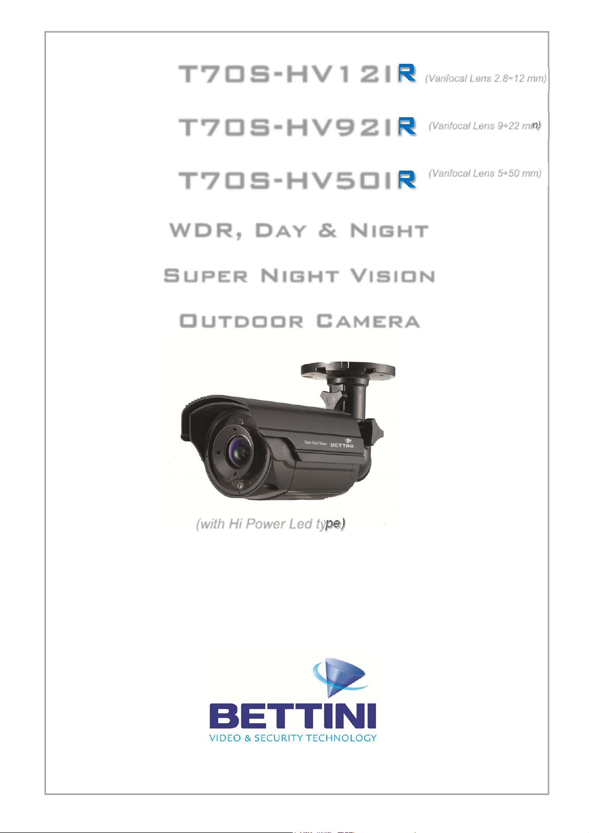
T70S-HV12IR
T70S-HV92IR
T70S-HV50IR
WDR, Day & Night
Super Night Vision
Outdoor Camera
INSTRUCTION & USE MANUAL
(Varifocal Lens 2.8÷12 mm)
(Varifocal Lens 9÷22 mm)
(Varifocal Lens 5÷50 mm)
(with Hi Power Led type)

2
Version1.0.2
Nov/2013
DearCustomers!
Byselectingthisproduct,youhavechosentouseaprofessionaldevicethatguaranteeshighestqualityand
reliability.Wewouldliketothankyouverymuchforyourconfidenceandrequestthatyoureadthe
followinginstructionscarefullybeforeinstallationandoperation.Youcanthentakefulladvantageofall
advancedfeaturesofthisproduct.
The lighting flash with an arrowhead symbol, within an equilateral triangle is
intended to alert the user to the presence of uninsulated dangerous voltage within
the product’s enclosure that may be of sufficient magnitude to constitute a risk of
electric shock to persons.
The exclamation point within an equilateral triangle is intended to alert the user to
the presence of important operating and maintenance (servicing) instructions in
the literature accompanying the appliance.
INFORMATION
This equipment has been tested and found to comply with limits for a Class A digital device,
pursuant to part 15 of the FCC Rules. These limits are designed to provide reasonable protection
against harmful interference when the equipment is operated in a commercial environment. This
equipment generates, uses, and can radiate radio frequency energy and, if not installed and used
in accordance with the instruction manual, may cause harmful interference to radio
communications. Operation of this equipment in a residential area is likely to cause harmful
interference in which case the user will be required to correct the interference at his own expense.
WARNING
Changes or modifications not expressly approved by the manufacturer could void the user’s
authority to operate the equipment.
CAUTION – To prevent electric shock and risk of the fire hazards
Do NOT use power source other than that specified.
Do NOT expose this appliance to rain or moisture.
CAUTION
TO REDUCE THE RISK OF ELECTRIC SHOCK,
DO NOT REMOVE THE COVER (OR BACK).
NO USER SERVICEABLE PARTS INSIDE.
REFER SERVICING TO QUALIFIED PERSONNEL
This installation should be made by a qualified service person and should
conform to all local codes.

3
Version1.0.2
Nov/2013
Table of contents
Installation Manual
1. Precaution 4
2. Limitation of liability 5
3. Disclaimer of warranty 5
4. Package 6
5. Special features of the model 7
6. Installation 8÷11
7. Trouble shooting guide 12 ÷ 13
8. Dimension (mm) 13
9. Specification 14
10. O.S.D. Functions & Operation 15 ÷ 26

4
Version1.0.2
Nov/2013
1. Precautions
Please read the manual carefully before installing this camera, in order to make sure the set up
is correctly and to obtain the best picture quality.
Please keep the manual safe and in good condition for future reference and servicing.
Installation and servicing should only be carried out by an authorised personnel, in line with
local safety regulations.
If any liquid leaks into the housing, immediately disconnect the camera from power supply and
have it checked by an authorized dealer before re-connecting it.
Avoid installing the camera in places that are extremely hot or cold.
If you are not a qualified person, never try to dismantle the camera. To avoid electric shock,
never remove the screws or covers. There are no parts inside that need maintenance by the
user. All maintenance should be carried out by qualified personnel.
Avoid installing the camera in places with high humidity.
Avoid installing the camera in places that are exposed to gas or oil.
Keep the polycarbonate dome, and the lens, clean to obtain the best picture quality. Be
especially careful not to leave fingerprints on the lens or dome cover.
Make sure the camera is not dropped and is protected from external shocks during the process
of transportation, handling and installation.
Never try to touch the camera with wet hand. It could cause an electric shock.
Do not expose the camera to radioactivity. It causes a serious damage on the sensor.

5
Version1.0.2
Nov/2013
2.Limitationofliability
This publication is provided “AS IS” without warranty of any kind, either express or implied,
including but not limited to, the implied warranties of merchantability, fitness for any particular
purpose, or non-infringement of the third party's right. This publication could include technical
inaccuracies or typographical errors. Changes are added to the information herein, at any time, for
the improvements of this publication and/or the corresponding product(s).
3.Disclaimerofwarranty
In no event shall the seller be liable to any party or any person, except for replacement or
reasonable maintenance of the product, for the cases, including but not limited to below:
(1) Any damage and loss, including without limitation, direct or indirect, special, consequential or
exemplary, arising out of or relating to the product.
(2) Personal injury or any damage caused by inappropriate use or negligent operation of the user.
(3) Unauthorised disassembly, repair or modification of the product by the user.
(4) Inconvenience or any loss arising when images are not displayed, due to any reason or cause
including any failure or problem of the product.
(5) Any problem, consequential inconvenience, or loss or damage, arising out of the system
combined with the devices of third party.
(6) Any claim or action for damages, brought by any person or organisation being photogenic
subject, due to violation of privacy with the result of that surveillance-camera's picture, including
saved data, for some reason, becomes public or is used for the purpose other than surveillance.

6
Version1.0.2
Nov/2013
4.Package
Camera x 1
Instruction Manual x1 Ext-Video Cable x1
Tapping screws Plastic anchor x 3 Power + Video Cable x 1

7
Version1.0.2
Nov/2013
5.Specialfeaturesofthemodel
1. Higher resolution of 600TVL(D)/650TVL(N)
This unit has come up with an innovative way of increasing cubic resolution to more than 30%
higher than that of conventional 600TVL cameras.
It upgrades horizontal resolution to 600TVL and vertical resolution to 540TVL so that the cubic
resolution becomes 324KTVL while conventional cameras provide only 240KTVL.
2. Unbeatable WDR Performance
This unit provides a very unique and far superior image scanning capability of defining the details
of differently contrasted areas compared with any other conventional WDR cameras. With current
WDR technologies, defining images in shaded areas are typically not clear enough with over‐
exposed picture quality. This camera provides a special resolution to intelligently analyze the
exposure ratio and to optimize it into an unbeatably clear image quality.
3. Super Low Light sensitivity
The system specifies itself as the best resolution in the market that overcomes the limitation of
compromising light sensitivity from conventional WDR cameras.
With its special technology, it provides remarkable low light sensitivity of 0.1Lux /F2.0 ~ 0.0001Lux
w/Sens‐up 512x which is at least 3 times better than any other conventional WDR cameras.
4. 2D/3D Noise Reduction
2D/3D DNR achievement is another reference in new WDR technology.
It reproduces noiseless images with 2D/3D filtering Noise Reduction Technology so that users can
save the volume of storage media and HDD capacity in DVR.
2D DNR helps preserved edged in the picture, while 3D DNR realizes clear images with no ghost
effect.
5. DIS (Digital Image Stabilizer)
This technology reduces blurring associated with the motion of the subject by using pixels outside
the border of the visible frame to provide a buffer for the motion.
Increasing the exposure time without blurring the image makes the moving subject stabilized
digitally.
6. Anti‐Color Rolling
With an operation of a wide dynamic range camera in an environment with a fluorescent lighting,
an effect that is called “color rolling” usually happens due to the lack of the synchronization
between the camera and the neon light.
New WDR technology tracks the light changes relative to the camera and adapts its own timing to
the periodicity of fluorescent illumination to the sample light at a constant phase, virtually
elimination the color rolling effect.

8
Version1.0.2
Nov/2013
6. Installation
6‐1. How to mount to Ceiling
①
Drillthreescrewholesontheceilingplatetofixthreeanchors(supplied)intheholes.
②
Fixtheplasticanchorsintheholes.
③
Positionthemountingbracketonthescrewpoints.
④
Fixthemountingbracketbytighteningthescrews.
⑤
Slightlyloosenbolt(A)thenadjustTILT(180°)androtation(360°)ofthecamerausinga
serrationonthebracketandtightentheboltfirmly.
⑥
Slightlyloosenbolt(B)thenadjustpan(360°)ofthecameraandtightentheboltfirmly

9
Version1.0.2
Nov/2013
6-2. How to install to Wall
① Drillthreescrewholesonthewallplatetofixthreeplasticanchors(supplied)intheholes.
② Fixtheplasticanchorsintheholes.
③ Positionthemountingbracketonthescrewpoints.
④ Fixthemountingbracketbytighteningthescrews.
⑤ Slightlyloosenbolt(A)thenadjusttilt(180°)androtation(360°)ofthecamerausinga
serrationonthebracketandtightentheboltfirmly.
⑥ Slightlyloosenbolt(B)thenadjustpan(360°)ofthecameraandtightentheboltfirmly.

10
Version1.0.2
Nov/2013
6-3. 3-Axis adjustment
① Pan 360˚
Slightly loosen Pan bolt then adjust pan of the camera using a serration on the
bracket and tighten the bolt firmly .
② Tilt 180˚
Slightly loosen Tilt bolt then adjust tilt of the camera using a serration on the bracket
and tighten the bolt firmly.
③ Rotation 360˚
Slightly loosen Tilt bolt then adjust rotation of the camera using a serration on the
bracket and tighten the bolt firmly.
6-4. Lens external adjustment

11
Version1.0.2
Nov/2013
6-5. EXT-Video
- How to use
Connect Extra video output (BNC cable) to LCD monitor as a picture.
6‐6 Waterproof processing of cable end connection
Makesuretouseabutyltape.(Donotuseasealingmaterialonthoseparts)
① Itisusefultoconnectthecableendsfromcameratotheextensioncableforwaterproof.
② Connectandtapethepowercables(Power‐Power/Ground‐Ground).
③ Bindthepowercablestogetherwiththetape.WhenDC‐Jackisused,tapetheDC‐DCjoint.
④ ConnectandtapetheRS485cables(RS485+ㅡTRX+/RS485‐ㅡTRX‐)
⑤ TapetheBNC‐BNCjoint.

12
Version1.0.2
Nov/2013
7.Troubleshooting
Ifthereareproblemsinoperating,pleaserefertothechecklistbelow.Iftheproblempersists,please
contacttheagentwherethisproductispurchased.
ProblemsTroubleshooting
Nothingappearsonthescreen.Pleasecheckthatthepowercordandlineconnection
betweenthecameraandmonitorarefixedproperly.
PleasecheckthatyouhaveproperlyconnectedVIDEO
cabletothecameraVIDEOoutputjack.
Theimageonthescreenisdim.Islensstainedwithdirt?Cleanyourlenswithsoft,
cleancloth.
Setthemonitortopropercondition.
Ifthecameraisexposedtotoostronglight,change
thecameraposition.
Theimageonthescreenis
dark.
Adjustthecontrastfeatureofthemonitor.
Ifyouhaveanintermediatedevice,setthe75Ω/Hi‐Zproperly
(Pleasechecktheimpedance)
Thecameraisnotworking
properly,andthesurface
ofthecameraishot.
Pleasecheckthatyouhaveproperlyconnectedthecamera
toanappropriatepowersource.
TheDAY/NIGHTmenu
doesnotwork.
PleasecheckifDAYNIGHTmenuissetto‘AUTO1’.
TheSENS‐UPfunction
doesnotwork.
PleasecheckthatAGCofEXPOSURESETUPmenuissetto
‘OFF’.
PleasecheckthatSHUTTERofEXPOSURESETUPmenuissetto
‘A.FLK’or‘FIXED’.
TheMOTIONDETECTION
functionisnotworking.
PleasecheckifMOTIONDETECTIONfunctionisturnedon.
PleasecheckifMDLEVEListoolow.
PleasecheckthesettingoftheMDarea.
Colorisnotcorrect.PleasecheckthesettingofWHITEBALSETUPmenu.
Thescreenflickerscontinually.
PleasecheckthatdirectionofcameraturnstowardtheSun.
13
Version1.0.2
Nov/2013
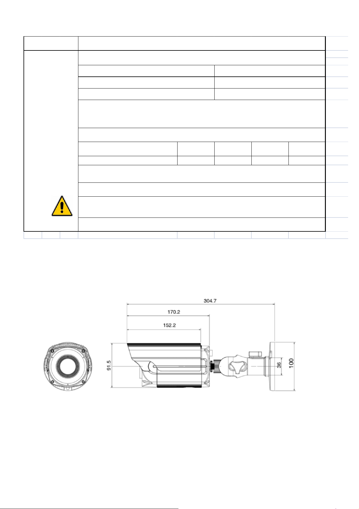
8.Dimension(mm)
Problems
Item Camera ID BAUD
RATE
UART
MODE RET PKT
Initial value 1 9600 8‐NONE‐1 ENABLE
RS‐485
communication
fails.
Troubleshooting
♦
Please check the polarity between RS‐485 Control Port and RS‐485 cable.
♦
Please check if the initial value of the RS‐485 Communication setup matches between
camera and OSD Controller or DVR.
*RS‐485 Communication establishment initial value
♦
We recommend that you make ground connection between camera and controller for
safe communication control.
♦
When RS‐485 cable is not properly connected,
A warning message ‘ERROR RS‐485 Connection. Please reconnect and Reboot’ is
displayed.
Then please turn off the power and connect the cable again.
485 Control Board Connection Port
(+)CONNECTION TERMINAL(TRX+)
(‐)CONNECTION TERMINAL(TRX‐)
RS‐485 Control Port
485‐
485+

14
Version1.0.2
Nov/2013
9.Specification
12VDC 12VDC/24VAC
120mA (IR Off) /52mA (IR On) 10mA (IR Off) /400mA (IR On)
CCD
Effective pixels
Resolution
Scanning Sys
Synchronization
Frequency
Min.Illumination
Video Out
S/N
Shutter Speed
Gamma Control
White Balance
Gain Control
IR Spectrum
Viewable
Distance
MTBF of IR
Operating Temp
Humidity
Image
2 : 1 Interlace
Power Source
Sync
Standard : ‐6dB~34dB Auto /Maximum by OSD
Electrical
1500°K~11,000°K Auto, ATW/Cor‐Roll/Push/Manual
0 Lux / IR On, 0.001 Lux / IR On
WDR SUPER NIGHT VISION CAMAERA
1/3” Sony Super HAD Ⅱ
NTSC : 768(H) x 494(V), PAL : 752(H) x 582(V)
600TVL (Day) / 650TVL (Night)
NTSC : 15.743KHz(H), 59.94KHz(V)
PAL : 15.625KHz(H), 50KHz(V)
Internal
1Vp‐p Composite 75 Ohm
Ratio More than 52dB(AGC Off)
NTSC :1/60~90,000/sec. PAL : 1/50~90,000/sec.
Standard : r=0.45
OFF/ON (8 Zones selectable)
Function
‐10°C~50°C
White Balance
Privacy Mask
OFF/ON
OFF/x2~ x512
2D/3DNR
Sens‐up
Class
OFF/ON (8 Zones selectable)
Motion Detection
OFF/x1~ x8.30
Auto, ATW/Cor‐Roll/Push/Manual
WDR
0%RH~90%RH
Environmental
104.3(W) x 96(V) x 277.3(L)
OFF/ON
Measurement
850nm 8Ø x 14ea
Up to 50M at moonless night
20,000 hours
IR LE D
Digital Zoom
15
Version1.0.2
Nov/2013
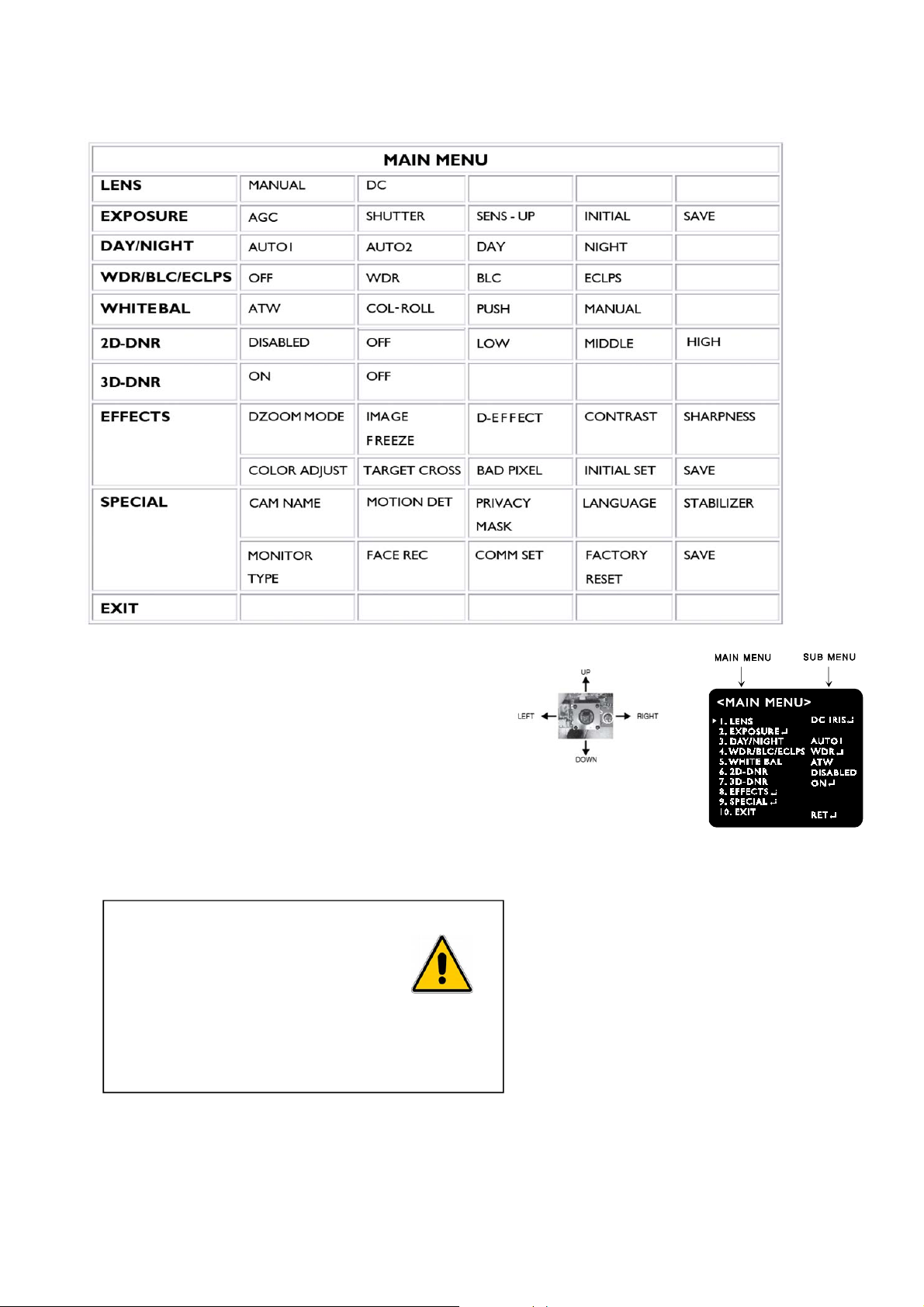
10. Functions and operation
1.OnScreenMenu(OSD)
2.Settingupthemenu
1.PresstheTactSWtoenter<MAINMENU>.
2.Movethearrowtoaspecificmenubypushingthe
TactSWupordown.
3.AdjusttheselectfeaturebypushingtheTactSWLeft
orRight.
4.Whencompleted,movethearrowindicatorto“EXIT”andpresstheTactSWtofinishallsetting.
How to use OSD button (Tact SW)
Press
-To enter the menu
-To save setting
Push up or down
-To select functions
Push left or right
-To adjust a level or mode of sub-menu

16
Version1.0.2
Nov/2013
Settings can be made using the 5 way button RS-485 wired remote control
1. Press the Button to access the SETUP mode.
The SETUP menu is displayed on the monitor.
2. Please select any function you wish to activate by using
the UP/DOWN selections.
The arrow can be moved up or down by using the UP/DOWN
selections.
Position the arrow to point to the function you wish to operate.
* Focus/ AF/ Zoom buttons on the packaged controller are not available with this unit.
3. Adjust the selected feature by pressing LEFT/RIGHT slections.
4. When completed, move the arrow indicator to ‘EXIT’ and press the SET to finish all settings.
Note
∙If‘‘indication appears on a selected sub-menu, press the SET to get into a following menu.
· If ‘ --- ‘ indication appears on any sub-menu, it means the function with this mark is deactivated.
(Ex : When SENS-UP is OFF, 3-DNR becomes deactivated ‘---‘ )
3.LENS
Select the lens and adjust the SETUP suitable to the type of lens.
WhenDClensisused.(
Default)
1.PleaseselectthelensmodetoDCIRIS.
2.PresstheSETtoenterthe<DCIRISMENU>.
‐BRIGHTNESS:adjustthebrightnessofscreenwhentheenvironmentis
extremelybrightordark.
‐REACTION:Reactionspeedoftheshutterisadjustable.
Itisusefulwhenthelightconditionoftheenvironment
keepschangingquickly.
3.Save
PressSAVEtofinishallsettingsandreturnto<MAINMENU>
WhenMANUALlensisused.
1.PleaseselectthelensmodetoMANUAL.
2.PresstheSETtoenterthe<MANUALIRISMENU>.
‐BRIGHTNESS:sameasabove
‐REACTION:sameasabove

17
Version1.0.2
Nov/2013
4.EXPOSURE
(1) AGC (Auto Gain Control)
- OFF: Deactivates the AGC function.
- LOW: Allows automatic gain control from 0 to 20dB. (Default)
- MIDDLE: Allows automatic gain control from 0 to 30dB.
- HIGH: Allows automatic gain control from 0 to 42dB.
The higher the gain level, the brighter the screen becomes while the higher the noise as well.
(2)SHUTTER
A.AUTO:Theshutterspeediscontrolledautomatically.(Default)
B.FLK:PleaseselectFLKmodewhenflickeringoccursonthe
screen,duetoanimbalancebetweenilluminationandfrequency.
C.FIXED:Theshutterspeediscontrolledmanually.
‐Youcanselectthespeedfrom‘1/60’to‘1/90,000sec.(NTSC),‘1/50’to‘1/90,000sec.(PAL).
‐YoucanselectDigitalSlowShutterbetweenx2~x512.(DSS)
PleaseuseFIXEDmodeonlywhenthelightlevelofthesurveillanceareaisfixedallthetime.
(3)SENS‐UP
‐Lowlightsensitivityisgreatlyimprovedwiththeuseofthisfunction.
‐Lowlightsensitivitylevelisadjustablefrom2to512times.
‐WhenSEN‐UPlevelishigher,thepicturebecomesbrighterwhilenoiseis
increasedatthesamerateofSENS‐UP.
ON:AdjustableSENS‐UPlevelbetweenx2÷x512.
OFF:SENS‐UPisdisabled.
Defaultsettingis<x8>
Note
∙WhentheSHUTTERissettoMANUALmode,SENS‐UPdoesnotoperate.
∙WhentheAGCissettoOFF,SENS‐UPdoesnotoperate.
18
Version1.0.2
Nov/2013
(4)INITIALSET
InitializeallsettingsofEXPOSUREmenu.
(5)SAVE
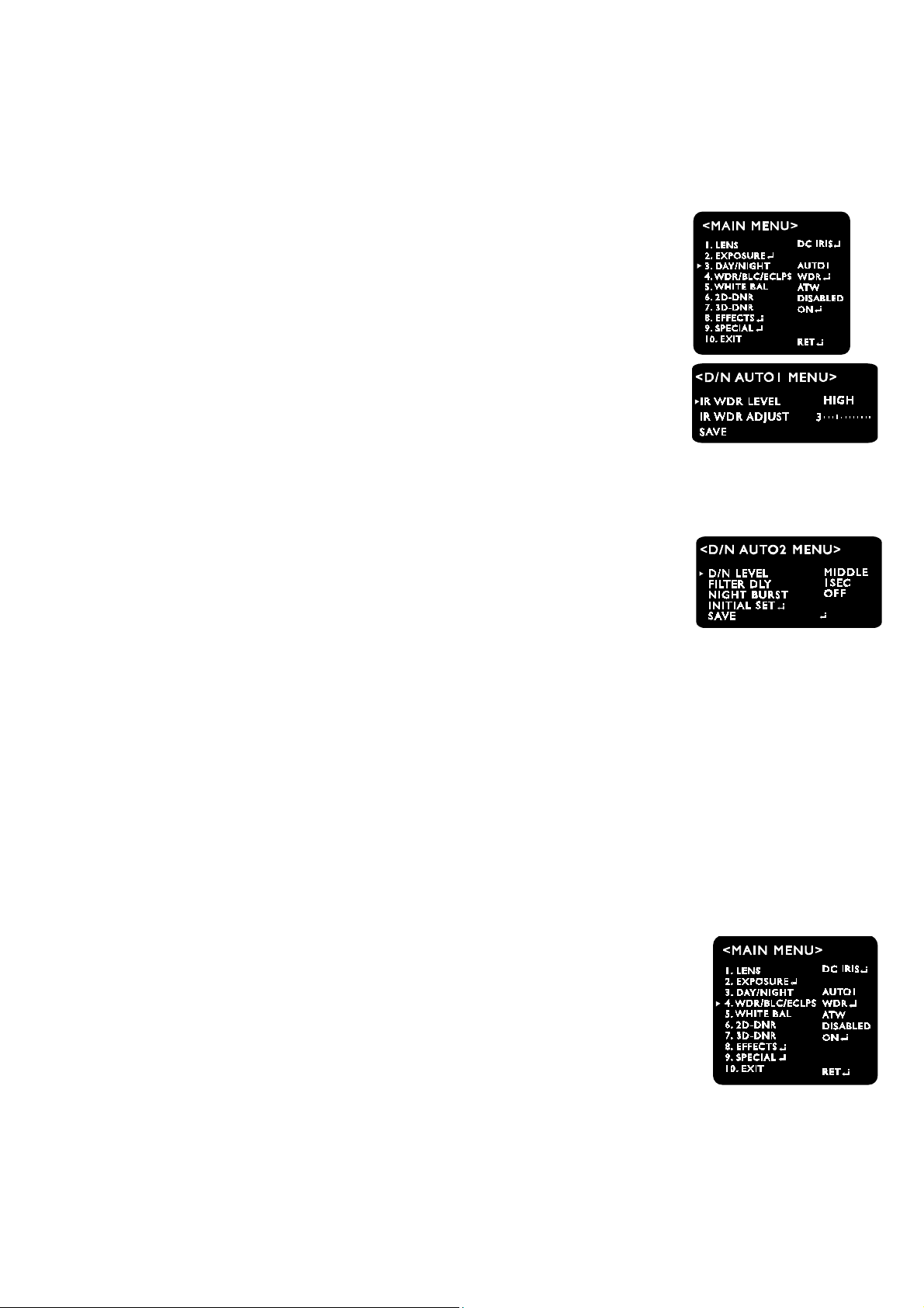
5.DAY/NIGHT
Itisusedtoimprovethesensitivityandclarityofpicturequalityatlowlight
‐DAY:Theimageisalwaysdisplayedincolor.
‐NIGHT:Theimageisalwaysdisplayedinblackandwhite.
‐AUTO1:TheimageisautomaticallyconvertedtoB/WfromColorat3lux.
IRWDRLEVEL:SelectAnti‐IRsaturationlevel‐OFF/LOW/MIDDLE/HIGH
IRWDRADJUST:Adjustthevalueineachofselectedlevel‐0~6
‐AUTO2:TheimageisautomaticallyconvertedtoB/WfromColorat3lux.
∙D/NLEVEL:LOW/MIDDLE/HIGH
∙FILTERDLY:SelectthedurationtimeaboutchangingtheDay/Nightmode.
(1SEC,3SEC,5SEC,10SEC,15SEC,30SEC,60SEC)
∙NIGHTBURST:BurstON/OFFselectable.
∙INITIALSET:InitializeallsettingsofAUTO2menu.
Defaultsetting
‐Infraredcamera:AUTO1
‐Non‐Infraredcamera:AUTO2
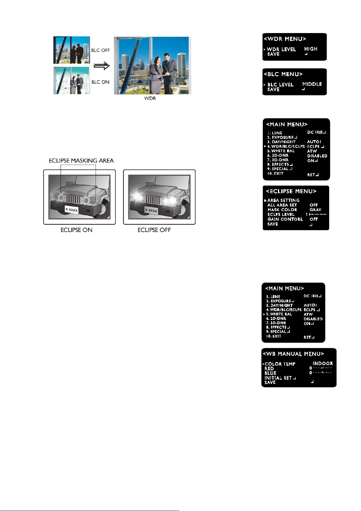
6.WDR/BLC/ECLPS
Theimagequalityisgreatlyimprovedwiththeuseofthismodewhenthereisastrong
backlightbehindtheobject.
‐OFF:DeactivatestheWDRfunction.
‐WDR:Camerascansbothofbrightlitbackgroundandshadedareadistinctively
underanextremelycontrastedlightsituation.(LOW/MIDDEL/HIGH)
‐BLC:Enablesausertodirectlyselectadesiredareafromapictureandtoviewtheareamoreclearly.
(LOW/MIDDEL/HIGH)
19
Version1.0.2
Nov/2013
‐ECLIPSE:
Canmasktheheadlightstoviewcarlicensenumberplatemoreclearly.
Canselectmaskingcolor.
AdjusttheECLIPSlevelattheGAINCONTROLasOFFmode.
7.WhiteBalance(WHITEBAL)
Thisisusefultooptimizethewhitebalalncecontrolunderacertainartificiallightingareawhereastandard
whitebalanceconditionisnotsuitable.
‐ATW(AutoTrackingWhiteBalance)
Thismodecanbeusedwithinthecolortemperature
rangeof1,500˚K~11,000˚K.(
Default)
‐COL‐ROLL
Anticolorrollingmode.
Useitonlywhentherollingisseverelyshown.
‐MANUAL
Recommandedtouseitwhenthelighttemperatureisfixedallthetime
SelectINDOORorOUTDOORmode.
‐PUSH(Pushlock)
UsethiswhentheWhiteBalanceisdeviated.
FacethecameratowardthewhitewallorwhitepaperandpresstheTactSW
20
Version1.0.2
Nov/2013
Note
WhiteBalancemaynotworkproperlyunderthefollowingcondition
‐Whenthecolortemperatureoftheenvironmentsurroundingthesubjectisoutofthe
controlrange.(e.g.clearskyorsunset)
‐Whentheambientilluminationofthesubjectisdim.
‐Ifthecameraisdirectedtowardsafluorescentlightorisinstalledinaplacewhere
illuminationchangedramatically,theWhiteBalanceoperationmaybecomeunstable.
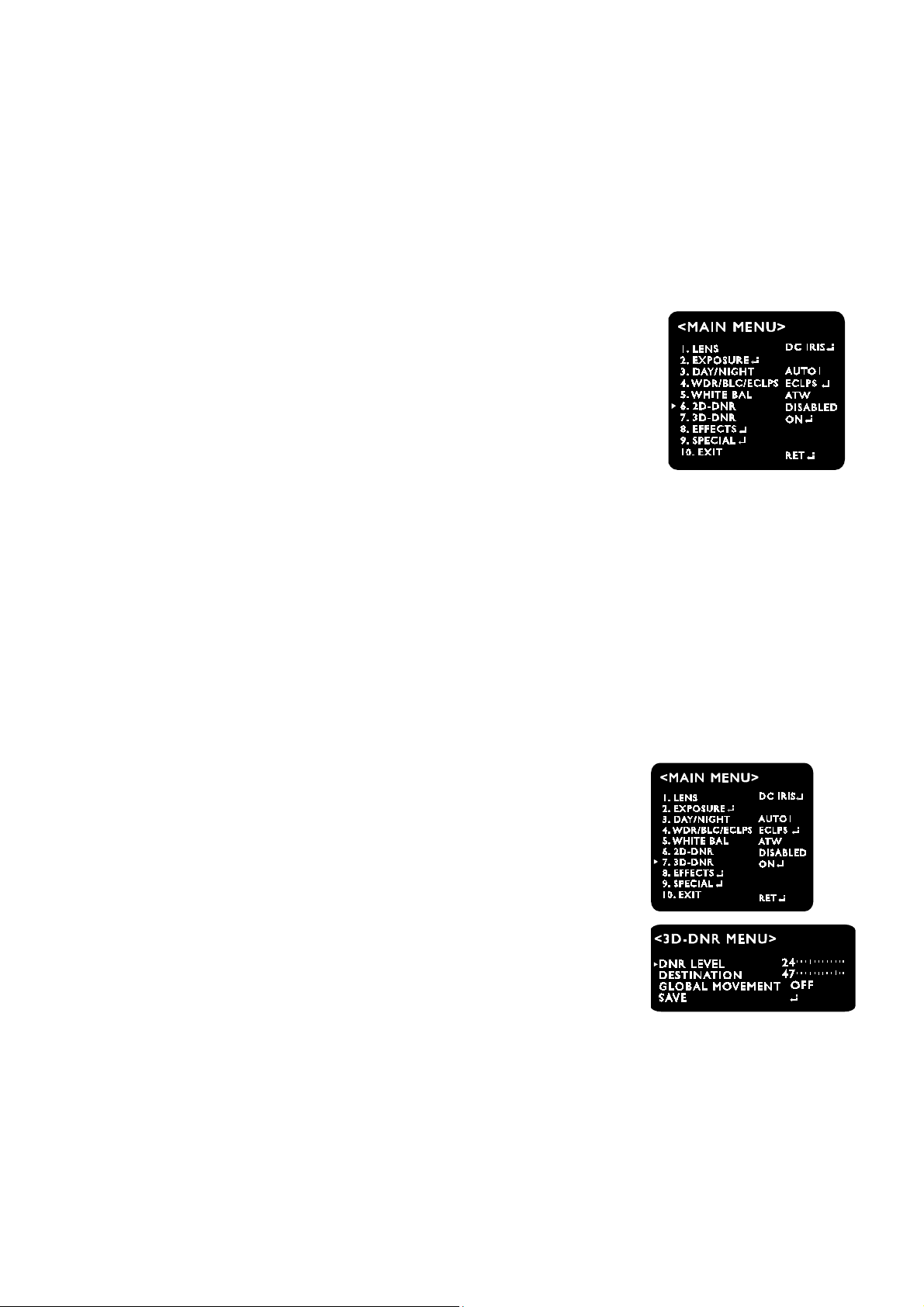
8.2D‐DNR(2DNoiseReduction)
‐LOW
‐MIDDLE
‐HIGH
‐DISABLED:Deactivates2DNR.Noiseisnotreduced.
‐OFF:Activates2DNR(Level:0).Noiseisnotreduced.
Note
<Badpixeldetection>functionisoperatedonlywhen<2D‐DNRDISABLED>isselected.
9.3D‐DNR(3DNoiseReduction)
Thebackgroundnoiseinthelowlightleveldecreasesautomatically
asthelevelofgainchanges.
‐DNRLEVEL
Adjustthenoisereductionlevel.
‐DESTINATION
Adjustthe3DNRgain.
‐GLOBALMOVEMENT
Controlghostphenomenon
This manual suits for next models
2
Table of contents
Other bettini Security Camera manuals


Popular Security Camera manuals by other brands


Tyco
Tyco Illustra Pro series quick start guide

Digital Watchdog
Digital Watchdog DWC-V7253TIR user manual

Mitsubishi
Mitsubishi DC-420E Operation manual

soloprotect
soloprotect ID Pro Start guide

LevelOne
LevelOne FCS-3072 Hardware user manual

Sanyo
Sanyo VCC-HD4600 - Full HD 1080p Day/Night Network... Product guide specification

American Dynamics
American Dynamics SpeedDome Optima LT Specifications

Hitachi
Hitachi HV-D20P Operation manual

TRENDnet
TRENDnet TV-IP501W user guide

Mobotix
Mobotix MOBOTIX M73 Quick installation

GeoVision
GeoVision GV-Fisheye GV-FE2301 user manual

Eneo
Eneo VKCD-1327ASFM Installation and operating instructions