BevLes PHC70-32-A User manual

Innovative Foodservice Equipment Custom
Designed for Performance, Service and Value.
INSTALLATION AND OPERATING
INSTRUCTIONS
Proofer/Holding
Cabinet
Models:
PHC70-32-A
PHC70-32INS-A
INTENDED FOR OTHER THAN HOUSEHOLD USE
RETAIN THIS MANUAL FOR FUTURE REFERENCE
UNIT MUST BE KEPT CLEAR OF COMBUSTIBLES AT ALL TIMES
This equipment has been engineered to provide you with year round dependable service when used
according to the instructions in this manual and standard commercial kitchen practices.
Toll Free: (844) 265-0250
Fax: (800) 548-9392
Website: www.BevLes.com
E-mail:
05/19
BevLes
1525 East Lake Rd
Erie, Pa 16511
!
FOR YOUR SAFETY
Do not store or use gasoline or other flammable vapors and liquids in the vicinity of
this or any other appliance.
!
!
WARNING
Improper installation, adjustment, alteration, service or maintenance can cause
property damage, injury or death. Read the Installation, Operating and
Maintenance Instructions thoroughly before installing or servicing this equipment.
!
The BevLes Company takes pride in the design and quality of our products. When used as intended and
with proper care and maintenance, you will experience years of reliable operation from this equipment. To
ensure best results, it is important that you read and follow the instructions in this manual carefully.
Installation and start-up should be performed by a qualified installer who thoroughly read, understands and
follows these instruction. If you have questions concerning the installation, operation, maintenance or
service of this product, write Technical Service Department BevLes Company, Inc., 1525 east Lake Rd. Erie,
PA 16511
TABLE OF CONTENTS
ITEM PAGE
Safety Precautions 1
General Information 2
Unpacking Instructions 3
Setting-Up
3
Operation Solid State Thermostat
4
Operation Digital Thermostat
5
Operating Tips 6
Safety and Health
6
Maintenance
6
Assistance/Service
7
Trouble Shooting
7
Additional Information 8
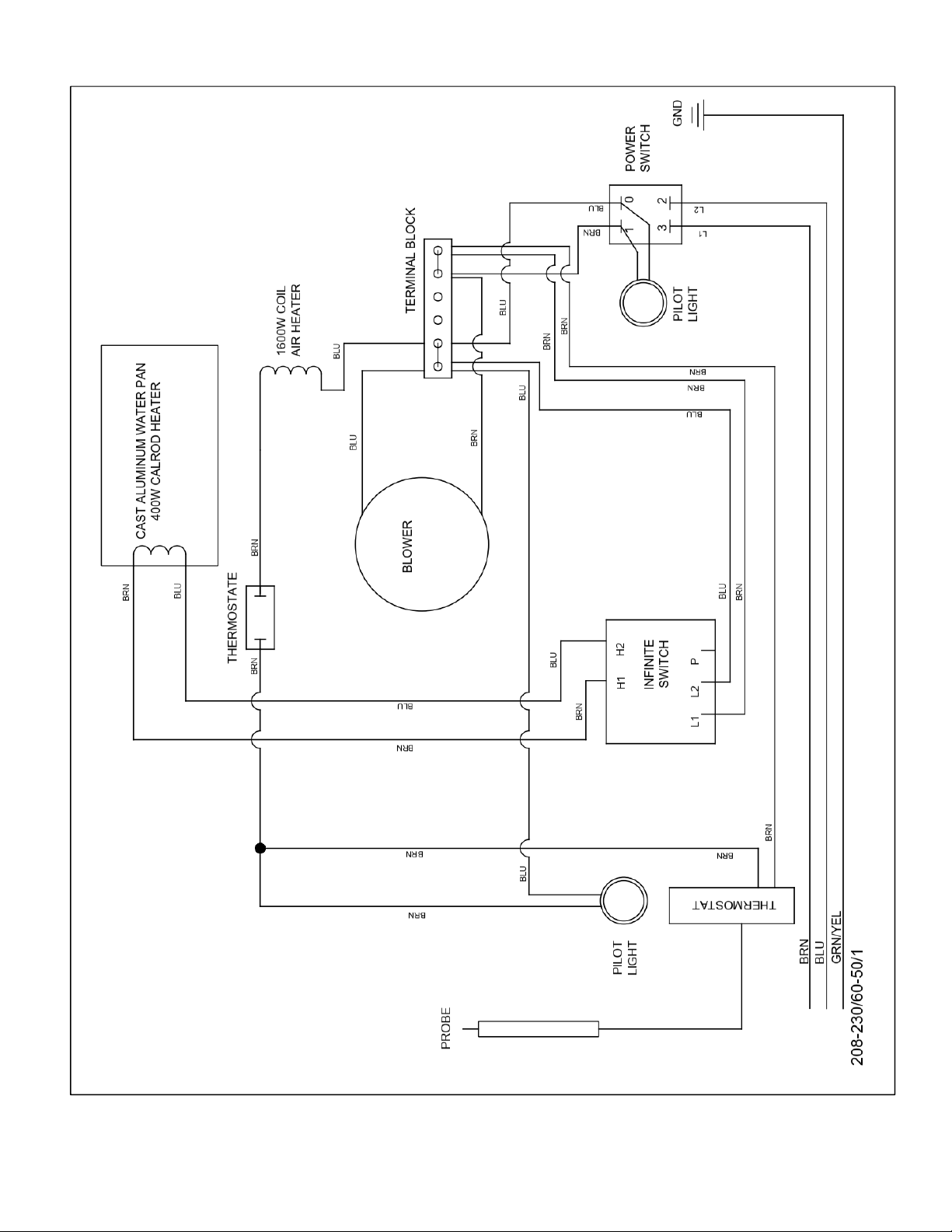
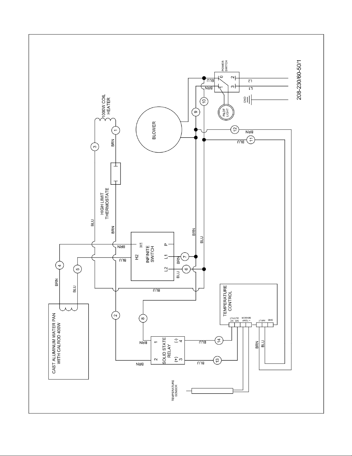
Wiring Diagrams 9,10,11,12
Parts List 13
Warranty 15
SAFETY PRECAUTIONS
Before installing and operating this equipment be sure everyone involved in its operation is fully trained and
aware of all precautions. Accidents and problems can result by a failure to follow fundamental rules and
precautions.
The following words and symbols, found in this manual, alert you to hazards to the operator, service
personnel or the equipment. The words are defined as follows:
DANGER: This symbol warns of imminent hazard which may result in serious injury or death.
WARNING: This symbol refers to a potential hazard or unsafe practice, which could result in
serious injury or death.
CAUTION: This symbol refers to a potential hazard or unsafe practice, which may result in minor or!
moderate injury or product or property damage.
NOTICE: This symbol refers to information that needs special attention or must be fully understood
! even though not dangerous.
THIS MANUAL SHOULD BE RETAINED FOR FUTURE REFERENCE

GENERAL INFORMATION
NOTICE: This product is intended for commercial use only. Not for household use.
CAUTION: These models are designed, built, and sold for commercial use. If these models are
positioned so the general public can use the equipment make sure that cautions, warnings, and
operating instructions are clearly posted near each unit so that anyone using the equipment will
use it correctly and not injure themselves or harm the equipment.
WARNING: Check the data plate on this unit before installation. Connect the unit only to the voltage
and frequency listed on the data plate. Connect only to 1 phase as listed on the data plate.
WARNING: Install per the spacing requirements listed in the installation section of this manual. We
strongly recommend having a competent professional install the equipment. A licensed electrician
should make the electrical connections and connect power to the unit. Local codes should always be
used when connecting these units to electrical power. In the absence of local codes, use the latest
version of the National Electrical Code.
WARNING: This device should be safely and adequately grounded in accordance with local
codes, or in the absence of local codes, with the National Electrical code, ANSI/NFPA 70, latest
edition to protect the user from electrical shock. It requires a grounded system and a dedicated
circuit, protected by a fuse or circuit breaker of proper size and rating. Canadian installation must
comply with the Canadian Electrical Code, CSAC22.2, as applicable.
NOTICE: Local codes regarding installation vary greatly from one area to another. The National
Fire Protection Association, Inc. states in its NFPA96 latest edition that local codes are “Authority
Having Jurisdiction” when it comes to requirement for installation of equipment. Therefore,
installation should comply with all local codes.
WARNING: SHOCK HAZARD De-energize and lock-out all power to equipment before
performing any maintenance, servicing or, cleaning of the equipment.
WARNING: SHOCK HAZARD Never clean any electrical unit by immersing it in water.
WARNING: SHOCK HAZARD - Operators should not open any panels that require the use of tools.
IMMEDIATELY INSPECT FOR SHIPPING DAMAGE
All containers should be examined for damage before and during unloading. The freight carrier has
assumed responsibility for its safe transit and delivery. If equipment is received damaged, either apparent
or concealed, a claim must be made with the delivering carrier.
A)
Apparent damage or loss must be noted on the freight bill at the time of delivery. It must then be signed
by the carrier representative (Driver). If this is not done, the carrier may refuse the claim. The carrier can
supply the necessary forms.
B)
If concealed damage or loss is not apparent until after equipment is uncrated, a request for inspection
must be made to the carrier within 15 days. The carrier should arrange an inspection. Be certain to hold all
contents and packaging material.
Installation and start-up should be performed by a qualified installer who has thoroughly read, understands
and follows these instructions.

UNPACKING INSTRUCTIONS:
Note: All Bevies cabinets are tested, inspected and expertly packed to insure arrival in a ready-to-use
condition. If any damage or loss is discovered when unpacking, ask the carrier's agent (in writing) to inspect
the product. This must be done within 15 days of delivery. You can then file a formal claim with the carrier.
This product has been shipped securely packed on a wooden pallet, covered with a protective bag and
corrugated shipping container and sealed with durable banding material. Carefully read the following
unpacking instructions and properly dispose of all packaging materials.
To open:
1.
Carefully cut and remove banding material.
2.
Carefully lift the corrugated container off the product.
3.
Remove the protective bag, tear, or tie several knots and appropriately place in a trash
container.
4.
Open door(s) and remove the carton containing the universal pan supports, and all packing
materials (tape, cardboard, etc.)
5.
Carefully lift cabinet off pallet.
6.
Check model number on the serial number label, located on the back of the unit.
7.
Release all wheel brakes
SETTING-UP
1.
Remove all protective film from interior and, exterior surfaces on cabinet, and doors
2.
Open the carton containing the universal pan supports and install all supports in cabinet. Install
the pan supports from the bottom up leaving one extra (unused) slot at the top of each of the four
uprights.
3.
Make certain that the polycarbonate water pan cover is properly installed over the cast water
pan and over the louvers in front of the pan.
4.
Insert a standard 18” x 26" sheet pan (not provided with proofer) in the slides under the base of
the cabinet. This will serve as a drip pan when cabinet is in use.
5.
Place the cabinet in the location where it will be operated. When in position secure the brakes on
the front two wheels. These brakes should always be locked when the cabinet is in use.
6.
Make certain that your unit is properly connected to the correct power source as specified on
the serial number label, located on the side of the unit.

OPERATION THERMOSTAT CONTROL
1.
Verify that wheel brakes are in locked position (front two casters).
2.
Inspect humidity pan for proper water level (1/2 to 3/4 full) for proofing.
3.
Make sure the polycarbonate water pan cover is properly in place with the holes over the pan.
Refer to picture of Solid State control panel below for the following steps.
4.
Set the temperature control to the desired cabinet temperature. 90°F to 110°F is recommended as
a starting position for proofing. Increase or decrease the cabinet temperature as needed to best
suit your application.
5.
Set the humidity control to the #3 or #4 position. This can be increased if necessary to suit your
specific application.
6.
Make certain that a standard 18" x 26" sheet pan (not provided) has been inserted as a drip pan in
the slides on the bottom "outside" of the cabinet.
7.
Verify that the door(s) is closed and latched.
8.
Push the power switch to the "ON" Position. Always use this switch to turn the unit "ON” or "OFF".
9.
Allow approximately 45-60 minutes for the cabinet to achieve the necessary temperature and
humidity that you desire.
10.
The cabinet is now ready for product placement, for proofing or holding.
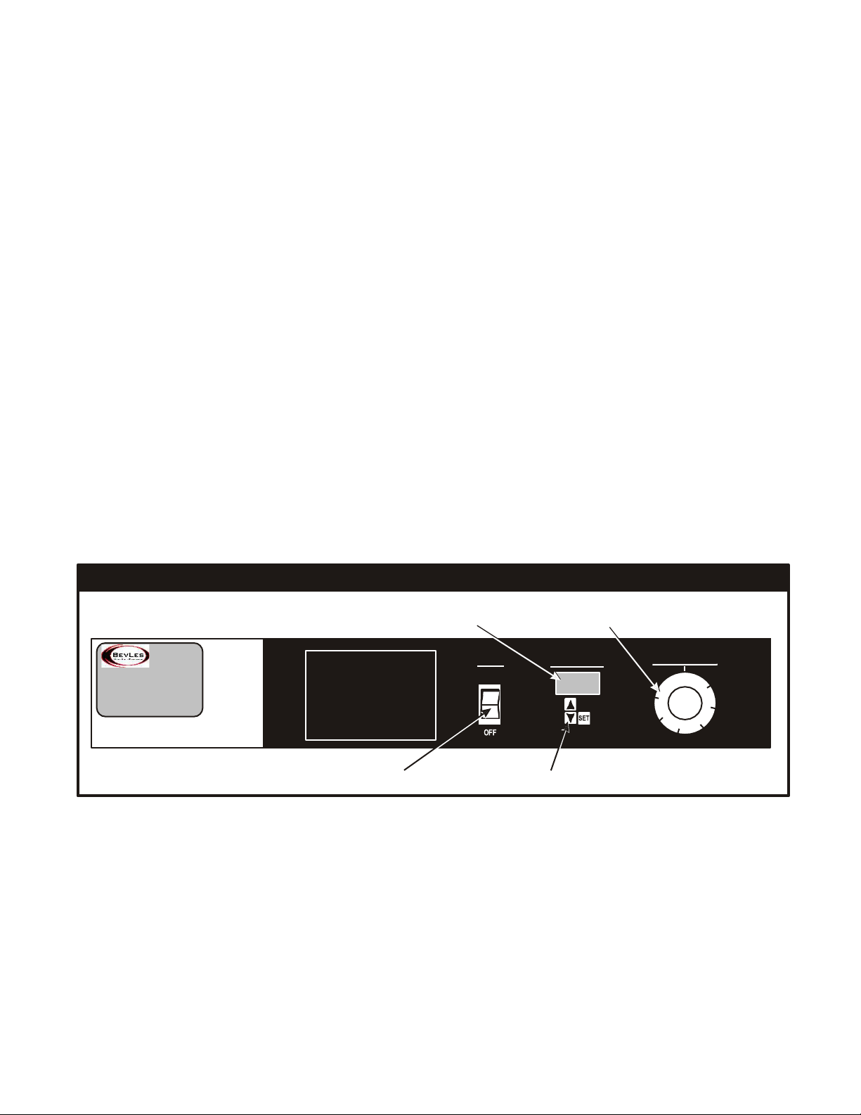
SOLID STATE CONTROL PANEL
Humidity
Control
Heater Indicator
Light
Power
Indicator Light
Temperature
Control
Power
Temperature
Guage
OPERATION DIGITAL THERMOSTAT
1. Verify that wheel brakes are in locked position (front two casters).
2. Inspect humidity pan for proper water level (1/2 to 3/4 full).
3. Make sure the polycarbonate water pan cover is properly in place with the holes over the pan.
Refer to picture of Digital control panel below for the following steps.
4. Push the power switch to the "ON" Position. Always use this switch to turn the unit "ON" or "OFF".
5. Set the temperature control to the desired cabinet temperature. 90°F to 110°F is recommended as a
starting position for proofing. Increase or decrease the cabinet temperature as needed to best suit
your application.
a. To select desired cabinet temperature:
b. Press SET key under cabinet temperature display. .
c. Press INCREASE key or DECREASE key to adjust cabinet temperature.
d. Press SET key to lock-in desired cabinet temperature. (If you don't press the SET key the
temperature setting will revert back to previous setting).
6. Set the humidity control to the #3 or #4 position. This can be increased if necessary to suit your
specific application.
7. Make certain that the 18" x 26" sheet pan (not provided) that has been inserted in the slides on the
bottom of the base is under the square hole to catch any condensation.
8. Verify that the door(s) is closed and latched.
9. Allow approximately 45-60 minutes for the cabinet to achieve the necessary temperature and
humidity that you desire.
10. The cabinet is now ready for product placement and the start of the proofing process.
DIGITAL CONTROL PANEL
Cabinet Temperature Display
Humidity Control
OPERATING INSTRUCTIONS
xxxxxxxx xxx xxx xxxxx xxxxx xxxxxxxx
xx xxxx xx xx x xxxxxxxx xx x xxxxxxxx xxxxx
xxxxxxxxxxxxxxxxxxxx xxxxxxxxxxx xxx xx
x x xxx xxxxx xx x xx xxx x xxxxx xx xxxxxxxx
xxxxxxxxxxxxxxxxx xxxxxxxxxxxxx xx xx xx x
xxxx xxxxxxxxxx xxxxxxxxx xxxxxxxxxxx xx
xxx xxxx xx xx xx xxxxxx xxxxxxxxxxxx xxxx x
POWER
ON
CABINET TEMP.
CABINET HUMIDITY
Power Switch
Temperature Control

OPERATING TIPS
Always inspect wheel brakes before attempting to move the cabinet. Make certain that brakes are in the
locked position before placing cabinet into operation.
During "cold" start-up you may want to set the Humidity Control to the HI setting for 10 to 15 minutes to
accelerate the humidity process. Remember to re-set the Humidity Control back to the desired setting
before beginning the proofing process. Once the cabinet has been loaded with product and the proofing
process has started, the door(s) should not be opened until proofing has been completed.
The 18" x 26" sheet pan (not provided) that serves as a drip pan under the cabinet base should be
checked, and if necessary, emptied at the end of each day.
The cabinet should be cleaned whenever necessary. It should be thoroughly cleaned at least once a week.
Note: It is recommended that humidity be kept at the minimum level that is practical for your operation.
Excessive humidity with condensation on the walls and/or base of the cabinet is not considered desirable.
SAFETY AND HEALTH
BevLes Proofing/Holding Cabinets meet all cUL and NSF requirements. Always operate this unit in
accordance with the operating instructions found in this manual. Never remove the humidity-heating
module without first disconnecting (unplugging) the unit from its power source. The cabinet is designed
and built for easy cleaning. It should be cleaned frequently as described in the maintenance section.
MAINTENANCE
Cleaning: This cabinet was designed and built for maximum sanitation. It is not self cleaning, so it should be
cleaned frequently with soap and water.
1.
NEVER USE STEEL WOOL OR CAUSTIC CLEANING COMPOUNDS.
2.
Make sure that the unit is turned OFF and disconnected from the electrical service.
3.
Remove the polycarbonate water pan cover and side covers from the humidity-heating
module.
4.
Remove the pan supports and vertical uprights.
5.
Remove the vent from the rear wall.
6.
Clean inside of cabinet with soap and water. Clean clear polycarbonate water pan cover and
door(s) with soft sponge, soap and water.
NEVER USE HARSH CLEANING SUBSTANCES OR ABRASIVES TO CLEAN LEXAN®
SURFACES, OR THE CAST ALUMINUM WATER PAN.
7.
Remove and clean the 18" x 26" drip pan (not provided) from under the cabinet base
If necessary, the humidity-heating module can be removed by loosening the two (2) black knobs (one
located at each side on the module on the exterior of the cabinet). The module can be pulled out of the
cabinet for additional cleaning. We suggest that you clean the water pan at least once a month with a
solution of white vinegar and hot water. Allow white vinegar to remain in water pan overnight. Then use a
soft cloth to wipe away any mineral buildup.
Important: When placing the humidity heating module back into the cabinet make certain that the module
is pushed tightly against the cabinet and secured with the two (2) black knobs. Check to see that the one
inch air flow opening at the rear of the humidity-heating module is behind the back vent that hangs on the
rear wall of the cabinet. This is necessary to maintain uniform temperature and humidity distribution
throughout the cabinet.
IF REPLACEMENT PARTS ARE EVER REQUIRED, ONLY USE PARTS THAT HAVE BEEN
APPROVED BY BEVLES COMPANY, INC.

ASSISTANCE I SERVICE
Should you ever require assistance or service contact the BevLes service line, at (844)265-0250 When
you phone please have the model number and serial number of the unit.. This will assist our service
technicians in providing you immediate assistance. You may want to briefly review the Troubleshooting
Tips before you contact our factory.
TROUBLESHOOTING TIPS
No Power
If your cabinet fails to start when the power is applied via power switch:
1.
Check to see if the unit is properly connected to correct power source as specified on the serial
number label.
2.
Check to see that your power source (wall receptacle) has power - inspect circuit breaker.
3.
Disconnect power cord and visually inspect for any damage.
4.
Contact the Bevies Technical Service Department tor assistance.
Excessive Humidity
If your cabinet is producing excessive humidity:
1.
Check the setting on the humidity control knob to see if it is set where you normally operate
at.
2.
Check the base of the cabinet to see if the excess humidity is draining through the drain hole in
the center of the base.
3.
Contact the BevLes Technical Service Department for assistance.
No Humidity
If your cabinet is producing no humidity, or considerably less than normally achieved:
1.
Inspect water level in the water pan.
2.
Check the humidity control knob to see if it is set where you normally operate at.
3.
Check to see if the cabinet door(s) is closed.
4.
Make certain that the humidity-heating module's one inch air flow opening (at rear of module) is
behind the cabinet back vent that hangs on the rear wall of the cabinet.
5.
Make certain that the polycarbonate water pan cover is correctly positioned over the entire
water pan and the louvers located in front of the water pan.
6.
Verify that the fan blower is operating.
7.
Contact the BevLes Technical Service Department for assistance.
Excessive Heat
If your cabinet temperature is higher than normal:
1.
Check the setting on the temperature control to see if it is set where you normally operate at.
2.
Check the ambient room temperature to see if it is greater than your desired proofing
temperature.
3.
Contact the BevLes Technical Service Department for assistance.
No Heat
If your cabinet is producing no heat, or considerably less than you normally achieve:
1.
Check the setting on the temperature control to see if it is set where you normally operate at.
2.
Check to see if the cabinet door(s) is completely closed.
3.
Make certain that the humidity-heating module's one inch air-flow opening (at rear of module) is
behind the cabinet back vent that hangs on the rear wall on the cabinet.
4.
Verify that the fan blower is operating.
5.
Contact the BevLes Technical Service Department for assistance.
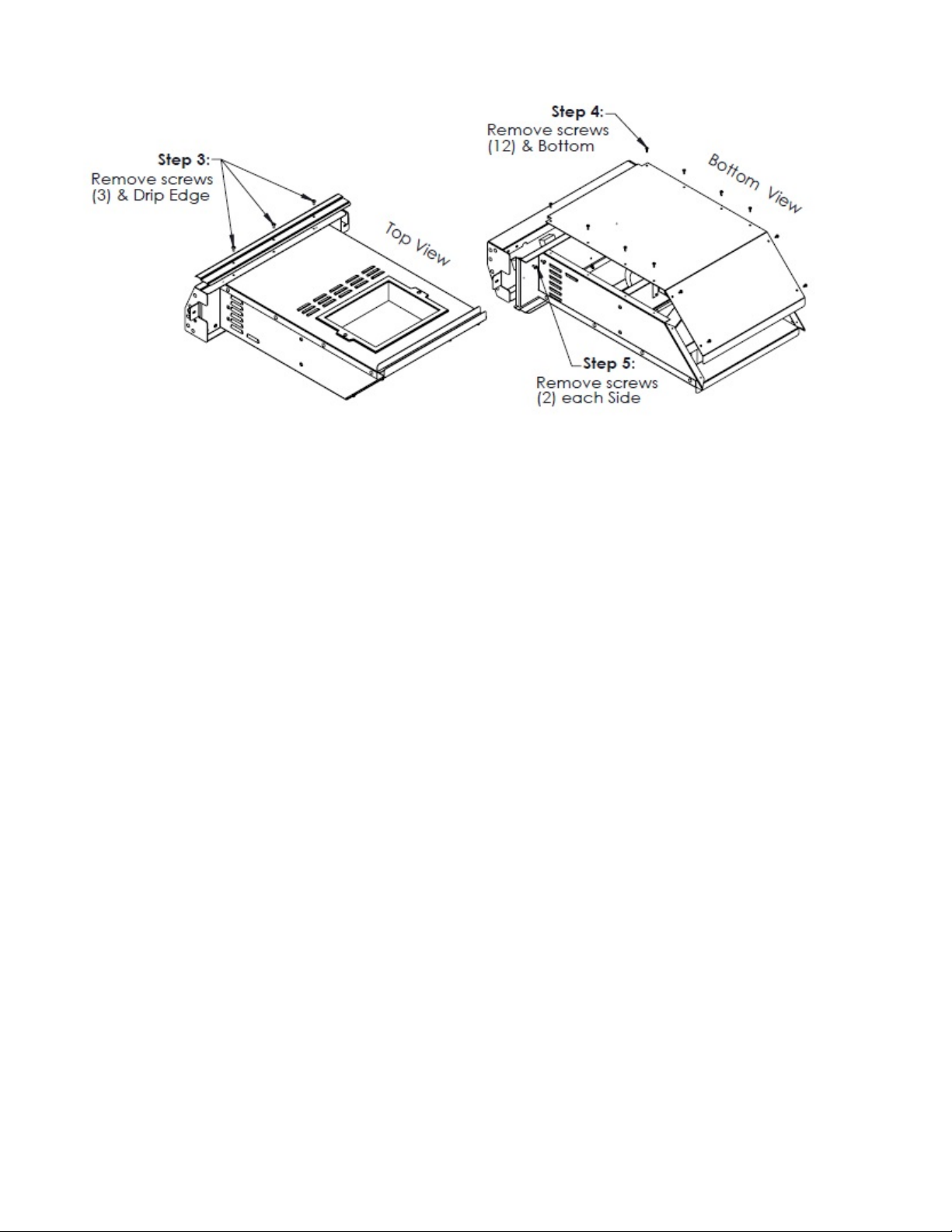
ADDITIONAL INFORMATION
Part Replacement Instructions
TO ACCESS ELECTRICAL COMPONENTS:
1.
Make sure the unit is turned off and disconnected from electrical service.
2.
Remove the two black handled knobs (one located on each side of the control panel).
3.
Pull the module out from the cabinet.
Refer to drawings above for steps 4, 5 and 6.
4.
Remove screws(3) and stainless steel drip edge.
5.
Turn module over, and remove screws from the bottom of the module. (6 screws each side).
There will be (4) nylon caps and spacers, save and reuse.
6.
Remove screws from the back side of control panel. (2 screws each side).
7.
Carefully pull control panel forward.
After installing any new components, reverse the above steps. Make certain that the one inch air-flow
opening at the back of the module is up behind the cabinet's back vent hanging on the rear wall.
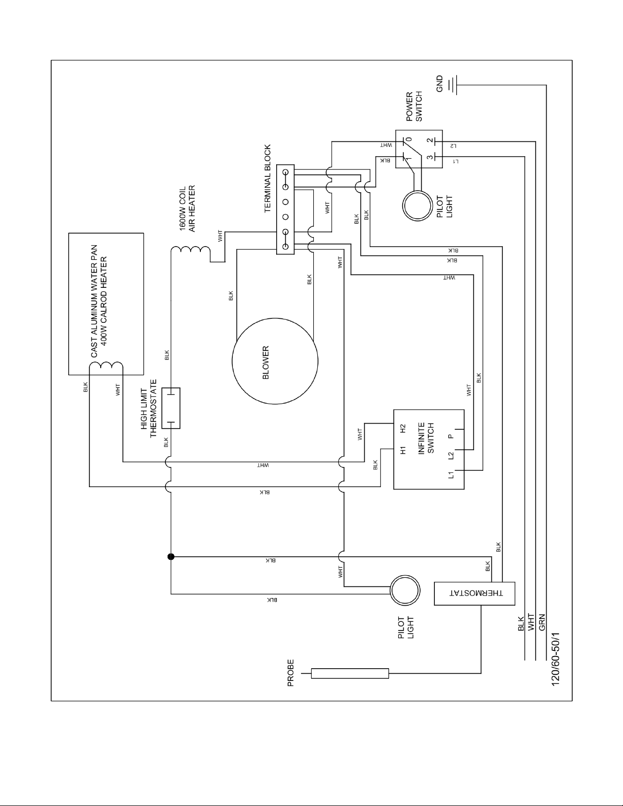
Refer to wiring diagrams for additional information.
120v Solid State Control Amp rating: 16.7 amps

120v Digital Control Amp rating: 16.7 amps
208/230v Solid State Control Amp rating: 9.7/8.7 amps
208/230v Digital Control Amp rating: 9.7/8.7 amps

Part Number Description
720671 Pin Hinge
740333 Hinge Right
740334 Hinge Left
750720 Pin, Latch
750419 Latch
781285 Latch Spring
750132 Latch, Butt
780036 Caster 5" Swivel w/Brake
780040 Caster 5" Swivel
783116 Knob Threaded 1/4-20 Bottom Module
781291 Knob Thermostat 80-180 degree
782092 Knob, Infinite Switch, Black
740352 Back Vent Panel
740368 Retainer, W iper Strip
702520 Wiper Blade Santoprene
741182 Vally Cover, Heating Unit Aluminum
760040 Water Pan Cover, Polycarbonate
784124 Handle, W ater Pan Cover
760028 Replacment Door Glass Polycarbonate, Single Door
760004 Replacment Door Glass Polycarbonate, Double Door
740223 Bracket, Mounting, Sensor
750420 Slide Glide (Pan Support)
740348 Vertical Upright, 1.50" Spacing
1488400 Thermostat 80-180 Degr ee 120/240v
784662 Temperatur e Controller Digital 120/240v
1302400 Switch, Rocker, DPST, 277V, 20A 120/240v
1107200 Block Terminal, 6 Station 600V
782162 Relay , Solid State, 50A-240VAC
784448 Transformer, 120/240V
780016 High Temperature Cut Out, Bi-Metal, 350°F, 40AMP 120/240V
782004 Heating Element Blower 1600W , 120V
784288 Heating Element Blower 1600W 240V
782036 Heating Element W ater Pan 400W , 120V
784304 Heating Element W ater Pan 400W , 240V
782088 Switch, Infinite, 120V /15A
782224 Switch, Infinite, 240V/15A
1509600 Pilot Light, Green (Power) 120/240V
45653000 Pilot Light, Amber (Heater) 120/240V
720850 Motor, Blower, & Housing 120V
720851 Motor, Blower & Housing, 240V
Replacement Parts Mechanical
Replacement Parts Electrical

Notes:
BEVLES COMPANY LIMITED WARRANTY
1525 East Lake Road • Erie, PA 16511
Phone: (844) 265-0250 Fax: (800) 548-9392
1.
Bevles warrants to the original purchaser that on the date the equipment is shipped (sold), it will be
free of defects in materials or workmanship. Bevles will, at it’s discretion, repair or replace, during
the warranty period printed below, any part that has a defect in material or workmanship that was
present when the product shipped from Bevles, and which manifests itself during the warranty
period under normal use and service.
Parts: Two* years from date of original shipment from the Bevles factory.
Labor: One** year from date of original shipment from the Bevles factory.
* Air Circulation Blower Assemblies (motors) and Power Switches shall be one year from date of
original shipment.
Calrod “Air” Heating Elements shall be three years from date of original shipment.
** All electrical components 120 days from date of original shipment.
2.
Bevles must be contacted, and pre-approval must be issued by the Bevles factory prior to any type
of service being performed. Bevles assumes no responsibility for any charges that were not expressly
authorized by the Bevles factory, or for any charges that exceed, in Bevles’sole judgement, normal and
customary amounts.
3.
Bevles will pay UPS Ground charges for any part that has a defect in material or workmanship that was
present when the product shipped from Bevles, and which manifests itself during the first year of the
warranty period under normal use and service. All warranty replacement parts will ship F.O.B. Bevles
factory, Erie, PA 16511.
4.
This warranty shall be void in its entirety if any abuse of, misuse of, alteration/modification of or
improper maintenance of original product occurs. If, at any time a claim is reported to Bevles, and the
purchaser is delinquent in payment for the product, warranty will not apply.
5.
Buyer’s Remedies-If a Bevles product fails due to a defect in material or workmanship in conformity
with the warranties in paragraph one, buyer shall notify Bevles of such failure within a reasonable time,
but in no event beyond fifteen (15) days of such discovery of defect in material or workmanship.
Bevles shall provide, in its sole discretion, either the repair or replacement of any defective or any non-
conforming part. Bevles specifically disavows any other representation, warranty or liability relating
to the continued use of the product.
6 Exclusion of consequential and incidental damages-In no event shall Bevles be liable for any
incidental, special, indirect, or consequential damages, whether resulting from non-delivery or from
the use, misuse, or inability to use the product, or from defects in the product, or from
Bevles’ own negligence or other tort. This exclusion applies regardless of whether such damages are
sought for breach of warranty, breach of contract, negligence, or strict liability in tort or under any other
legal theory.
7. Disclaimer of warranties-The warranties contained in paragraph one above are the exclusive
warranties given by Bevles and supersede any prior, contrary, or additional representations,
whether oral or written. Bevles hereby disclaims and excludes all other warranties-whether
expressed, implied, or statutory-including any warranty of merchantability, any warranty of
fitness for a particular purpose, and any implied warranties otherwise arising from course of
dealing or usage of trade.
12/15

Innovative Foodservice Equipment Custom
Designed for Performance, Service and Value.
Toll Free: (844) 265-0250
Fax: (800) 548-9392
Website: www.BevLes.com
E-mail:
BevLes
1525 East Lake Rd
Erie, Pa 16511
This manual suits for next models
17
Table of contents
Other BevLes Commercial Food Equipment manuals

Popular Commercial Food Equipment manuals by other brands


Diamond
Diamond AL1TB/H2-R2 Installation, Operating and Maintenance Instruction

Salva
Salva IVERPAN FC-18 User instructions

Allure
Allure Melanger JR6t Operator's manual

saro
saro FKT 935 operating instructions

Hussmann
Hussmann Rear Roll-in Dairy Installation & operation manual

Cornelius
Cornelius IDC PRO 255 Service manual

Moduline
Moduline HSH E Series Service manual

MINERVA OMEGA
MINERVA OMEGA DERBY 270 operating instructions

Diamond
Diamond OPTIMA 700 Installation, use and maintenance instructions

Diamond
Diamond G9/PLCA4 operating instructions

Cuppone
Cuppone BERNINI BRN 280 Installation

Arneg
Arneg Atlanta Direction for Installation and Use