BEXT XL300 User manual
BEXT Inc. 1045 Tenth Avenue San Diego, 92101 – 1 619 239 8462 – www.bext.com
XL300
FM Exciter / Transmitter
Installation and Operation Manual


THIS DEVICE COMPLIES WITH PART 15 OF THE FCC RULES. OPERATION IS SUBJECT TO THE FOLLOWING TWO
CONDITIONS: (1) THIS DEVICE MAY NOT CAUSE HARMFUL INTERFERENCE, AND (2) THIS DEVICE MUST ACCEPT
ANY INTERFERENCE RECEIVED, INCLUDING INTERFERENCE THAT MAY CAUSE UNDESIRED OPERATION.
NOTE: THE GRANTEE IS NOT RESPONSIBLE FOR ANY CHANGES OR MODIFICATIONS NOT EXPRESSLY
APPROVED BY THE PARTY RESPONSIBLE FOR COMPLIANCE. SUCH MODIFICATIONS COULD VOID THE USER’S
AUTHORITY TO OPERATE THE EQUIPMENT.
NOTE: This equipment has been tested and found to comply with the limits for a Class B digital device, pursuant to
part 15 of the FCC Rules. These limits are designed to provide reasonable protection against harmful interference
in a residential installation. This equipment generates uses and can radiate radio frequency energy and, if not
installed and used in accordance with the instructions, may cause harmful interference to radio communications.
However, there is no guarantee that interference will not occur in a particular installation. If this equipment does
cause harmful interference to radio or television reception, which can be determined by turning the equipment off
and on, the user is encouraged to try to correct the interference by one or more of the following measures:
- Reorient or relocate the receiving antenna.
- Increase the separation between the equipment and receiver.
-Connect the equipment into an outlet on a circuit different from that to which the receiver is connected.
-Consult the dealer or an experienced radio/TV technician for help

Contents
1. Safety information 5
1.1 About Safety......................................................................................................................... 5
1.1.1
Electrical Hazards ..................................................................................................................... 5
1.1.2
Symbols and markings on the equipment ................................................................................ 6
1.1.3
Other Hazards ........................................................................................................................... 6
1.2 Safety Precautions ............................................................................................................... 7
1.2.1
Personal Safety ......................................................................................................................... 7
1.2.2
Site Safety ................................................................................................................................. 8
1.2.3
Equipment Safety...................................................................................................................... 9
1.2.4
First Aid ................................................................................................................................... 10
2. Technical support and warranty 11
2.1 Technical support ............................................................................................................... 11
2.1.1
Contacting technical support.................................................................................................. 11
2.1.2
Shipping your equipment for repair ....................................................................................... 11
2.2 Warranty Policies ............................................................................................................... 12
2.2.1
Warranty starting date........................................................................................................... 13
3. Unpacking transportation & storage 14
3.1 Before opening the box ..................................................................................................... 14
3.2 Checking box contents ....................................................................................................... 14
3.2.1
Box Content ............................................................................................................................ 14
3.2.2
Thumb Drive content .............................................................................................................. 15
3.3 Unpacking .......................................................................................................................... 15
3.4 Shipping and storage ......................................................................................................... 15
3.4.1
Storage ................................................................................................................................... 15
4. Introduction 17
4.1 Basic Description ................................................................................................................ 17
4.2 Front panel Description ..................................................................................................... 18
4.3 Rear Panel Description ....................................................................................................... 19
4.4 Technical Specifications ..................................................................................................... 20
4.4.1
General ................................................................................................................................... 20
4.4.2
Monoaural Operation ............................................................................................................. 20
4.4.3
Stereo Operation .................................................................................................................... 20
4.4.4
Multiplex Operation ............................................................................................................... 21
4.4.5
AES/EBU Operation ................................................................................................................ 21
4.4.6
SCA, RDS, AUX Operation ....................................................................................................... 21
4.4.7
Audio-Over-IP (Optional) ........................................................................................................ 21
4.4.8
Electrical and Noise ................................................................................................................ 21
4.4.9
Environmental and Physical ................................................................................................... 21
5. Installation and Use 22
5.1 Before Installation .............................................................................................................. 22
5.1.1
AC Power Protection ............................................................................................................... 22
5.1.2
RF Protection .......................................................................................................................... 22
5.1.3
Safety Interlock ....................................................................................................................... 22
5.2 AC Power Connection ........................................................................................................ 23
5.2.1
Surge Protection ..................................................................................................................... 23
5.2.2
Operating Voltage and Current, Fuse ..................................................................................... 23

5.2.3
Grounding ............................................................................................................................... 23
5.2.4
AC Power Connection ............................................................................................................. 23
5.3 Initial Power-Up ................................................................................................................. 24
5.4 Menu Structure .................................................................................................................. 25
5.4.1
Frequency ............................................................................................................................... 25
5.4.2
Power ...................................................................................................................................... 25
5.4.3
Audio....................................................................................................................................... 26
5.4.4
Settings ................................................................................................................................... 27
5.4.4.1 LAN ............................................................................................................................. 28
5.4.4.2 Time ........................................................................................................................... 28
5.4.4.3 DB25 Connector ......................................................................................................... 29
5.4.4.4 RS485 Address ............................................................................................................ 29
5.4.4.5 19 kHz Output Amplitude ........................................................................................... 29
5.4.4.6 19 kHz Deviation Amplitude ....................................................................................... 29
5.4.4.7 19 kHz Deviation Phase .............................................................................................. 29
5.4.4.8 Power Reduction ........................................................................................................ 29
5.4.4.9 Set FSK ........................................................................................................................ 29
5.4.4.10 Audio Changeover .................................................................................................... 29
5.4.4.11 AES/EBU ................................................................................................................... 30
5.4.4.12 Options ..................................................................................................................... 30
5.4.5
Presets .................................................................................................................................... 30
5.4.6
Alarms .................................................................................................................................... 31
5.5 Web Server ......................................................................................................................... 31
6. IP Audio with the IPA400 Option 33
6.1 Accessing the Stream Decoder .......................................................................................... 33
6.2 Configuring the IPA400 – Basic Settings ............................................................................ 34
6.2.1
Configuring the IPA400 – Advanced Settings ......................................................................... 35
6.2.2
Streaming ............................................................................................................................... 36
6.2.3
Audio....................................................................................................................................... 38
6.2.4
Security ................................................................................................................................... 38
6.3 Reboot ................................................................................................................................ 39
Appendix A – Rear Panel DB Connector Pinouts .................................................................................... 39
Appendix B - Touch Screen Calibration .................................................................................................. 40
Appendix C – Upgrade Firmware ........................................................................................................... 41
Appendix D – Log Event and Alarms List ................................................................................................ 43

XL300 - Installation and Use
Page 4
Proprietary Information
This manual contains information protected under Copyright of Bext Corporation. All rights are
reserved.
This manual shall not be reproduced or photocopied, in whole or in part, without written permission
from Bext Incorporated.
Only the customer to whom this manual has been supplied is permitted to use the information herein
contained. This documentation is to be used only for installation, commissioning, operation, and
maintenance of the equipment to which the manual refers. The manual can be transferred to third
parties only in cases where the transfer is integral part of the product sale, or Bext has given written
permission.
Symbols
conventions
Notes marked with this symbol refer to those procedures whose non-observance can
cause damage or malfunction to the equipment itself and / or other equipment
connected to it.
Notes marked with this symbol refer to those procedures whose nonobservance can
compromise safety of personnel.
Notes marked with this symbol refer to those procedures which are important for the
correct operation of the transmitter.
XL300 Installation and Operation Manual
Revision 1
© BEXT Inc.
1045 Tenth Avenue, San Diego, CA 92101
If you have any comment that could help us to improve this document, please write to bext@bext.com.
we will be happy to consider your input.
Thank you for choosing BEXT!

XL300 - Installation and Use
Page 5
1. Safety information
This chapter provides information about safety procedures and their application while using or
servicing the equipment described in this manual.
1.1 About Safety
All BEXT products are designed to meet the requirements of internationally approved electrical safety
criteria.
The removal of any cover or protective panel that can be only opened using a tool is
considered a maintenance activity, and that any person performing a maintenance activity
it is expected to be properly trained for such activity.
Under International Safety Standard EN60215, it is assumed that trained personnel will be
knowledgeable, and will take all the precautions necessary to operate safely.
1.1.1 Electrical Hazards
To remove power from the equipment, switch off and lock out the AC power. Put the lock out device
on the breaker that feeds AC to the equipment. Follow specific lock out and safety procedures in use
where the equipment is located.
Use a proper look out procedure to ensure that another worker cannot accidentally reapply
power while you are performing maintenance on any part of the transmitter, site, or antenna
system. Before opening the equipment and touching any internal part, remove and solidly
connect the antenna to ground.
It is not enough to switch off the equipment. The power line it is still connected. Disconnect
and lock out the upstream supply before servicing.
After turning off the AC power, always perform a measurement to confirm the power is off
before touching anything within the equipment. If the wrong breaker was opened, the
equipment may be subjected to live voltage.
Do not use an ordinary multi-meter to check for voltage. The instrument could have been
inadvertently left in the Ampere (A) range. This could cause a short circuit and an arc blast
that could result in severe burns or other injury.
Use a non-contact voltage probe or a safety voltmeter to conduct the voltage test.
Use a proper lock-out procedure to ensure that another worker cannot accidentally reapply
power while you are performing maintenance on any part of the transmitter, site, or
antenna system. Before opening the equipment and touching any internal part, remove
and solidly connect to ground the antenna connection.
XL300 - Installation and Use
Page 6
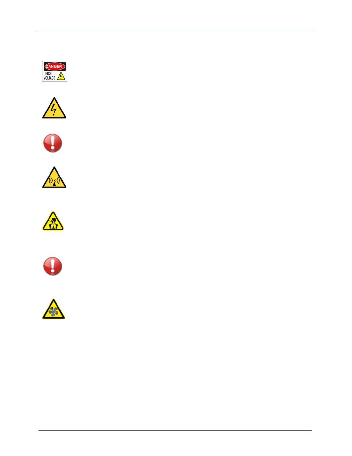
1.1.2 Symbols and markings on the equipment
DANGER! High Voltage
This label indicates that dangerous voltages (more than 72 volts), capable of
causing a fatal electric shock, are present on or near parts bearing this label.
Lightning Hazards
Before opening the equipment and touching any internal part, remove and
solidly short circuit the antenna feed line leaving it disconnected.
It is not enough to ground the antenna terminal with the antenna still
connected. Even a little impedance in the ground strap could result in lethal
voltages during a lightning strike.
RF Energy Hazard
Serious RF Hazard and extremely high voltages could be present in the vicinity
of the RF output, and related electrical networks, during normal operation.
Toxic Hazard
Some devices used in this equipment contain Beryllium Oxide ceramic, which
is not harmful during normal device operation, and under normal device failure
conditions. These devices are specifically identified with “BeO” in the
Description column of the Service Section parts list.
Do not crush, grind, or otherwise break the case of these devices because the
resulting powder may be hazardous if inhaled. Not serviceable parts and
devices should be in any case disposed as toxic waste.
DANGER! Moving Parts!
Fans can start at any moment and their blades can cause injury. Lock out power
before removing safety protections from fans and any other moveable part.
1.1.3 Other Hazards
Ensure that the appropriate fire alarms and fire extinguishers are available and in a proper state of
maintenance. Fire extinguishers must be suitable for use on electrical fires.
Many other site or equipment safety hazards exist. It is beyond the scope of this manual to identify
all the risks and related procedures to avoid them.

XL300 - Installation and Use
Page 7
1.2 Safety Precautions
Training of any personnel who will have physical access to the site or the equipment is particularly
important. Personnel must be familiar with the equipment, so that they can avoid exposing
themselves to potential dangers.
1.2.1 Personal Safety
Familiarize all new personnel to the safety procedures in use for the site and the
equipment. It is a good idea to give a site orientation class which should cover the
following topics:
Securing the site (locking doors and fences) to prevent unauthorized access.
How and when to call for technical support or emergency assistance.
Areas of the site and equipment that are off-limits.
Ensure that all personnel who can access areas with high voltage circuits or presence of
high RF field strengths are aware of the hazard associates with high voltage. Cover the
following topics:
Awareness of high voltage or high RF field strength areas where caution is required.
Awareness of physical risk of electric shock.
Risks for personnel with peacemakers or other sensitive medical devices.
Induced voltages in high field strength areas.
On-site risks during thunderstorms and lightning strikes.
Operation of safety interlocks if applicable.
XL300 - Installation and Use
Page 8
1.2.2 Site Safety
Site safety is maintained by implementing safety rules and procedures which have to be strictly
followed by all personnel who have access to the transmitting site.
As a minimum the following should be implemented to guarantee safety of employees and
equipment:
Controlling access:
RF devices and antennas generate and carry dangerous voltages that can be
harmful or fatal. It is especially important that the site and the equipment therein
are secured with a controlled access system. As a minimum, you should use
locking security doors (better if made of steel), a perimeter fence to keep away
unauthorized people from the antenna and its feedline, and an alarm system. “No
Trespassing” signs should be posted on the fence and doors.
Marking hazards:
Place warning signs close to any hazardous area (e.g., the feedline or the antenna
system). Make the signs large enough that they cannot be missed. Provide the
signs in all languages used in the region. These signs are intended not only for
authorized personnel, but also for emergency responders and accidental
trespassers.
Ac Power Protection:
Protect station equipment by installing surge protectors at the transmission site.
These should be installed at the main point of entry for the ac power, immediately
after the utility company meter and main breaker.
Power surges may occur during thunderstorms or malfunctions in the electrical
distribution grid. Surge suppressors and ac power conditioners can prevent
serious damage to all your on-site equipment.
RF Protection:
RF devices and their antennas systems create intense radio frequency fields at the
transmitter site, particularly near the feedline, antenna, and antenna tower. At
some sites, these fields can be so intense that they cause biological effects,
including the heating of body tissues. Intense RF fields can also create dangerous
high voltages on ungrounded conductive surfaces and objects. At certain points
where high voltages conductors come close to grounded conductors (e.g., at feed-
line junctions or on the antenna tower), dangerous arching or flash-over can
occur. It is particularly important that you take steps to prevent damage to
equipment or personnel due to RF fields.

XL300 - Installation and Use
Page 9
Safety interlocks:
All RF power equipment built by BEXT is provided with an external interlock circuit
which can be connected to external safety devices. When such circuit is electrically
open, the RF output of the equipment is immediately interrupted. Once the circuit
is closed again, the RF output will be immediately re-activated.
Summary:
Use safety interlocks to isolate equipment from ac power lines when opening panels.
Place warning signs in any locations where high fields can occur.
Train personnel about short term and long-term effects of RF radiations exposure.
Physically block access to the area around the antenna system, feedline, and tower.
Ground all exposed conductive surfaces or objects in high field areas.
1.2.3 Equipment Safety
The equipment has been designed to be rugged and resistant to damage. However, it is possible for
damage to occur because of extremely high voltage electrostatic discharge during servicing.
Technicians opening the equipment and touching internal parts should do so only after having bled
off any accumulated electrostatic charge on themselves by touching a well-known metallic grounding
surface.
Surge Protection:
Surge protection is recommended for your entire site. However, even if you do
not use a surge protector on the service entrance to the site, we recommend
that you install one in the equipment’s power feed to prevent over-voltage to
reach it and potentially cause damage.
Lightning Protection:
The equipment incorporates built in lightning protection devices. However,
particularly intense or repeated strikes could still cause severe damage. We
recommend that you install lightning suppression on the feedline to reduce
the effects of lightning strikes on the equipment itself, and to protect the rest
of your site equipment and your personnel.

XL300 - Installation and Use
Page 10
Physical Protection:
Consider the possibility of physical hazards to equipment at your site. Ensure
that equipment is protected from weather events, like rain or flooding, even
during extreme weather conditions. Place equipment so that is not in the path
of swinging doors or high traffic areas. Do not allow wheeled items like office
chairs, or carts close to equipment as these may damage front panels and
components if accidentally pushed or knocked over. Do not place equipment
under water pipes, AC system units or devices, drains, or sprinklers. Keep the
equipment away from flammable materials like ceiling panels, cubicle
dividers, or curtains.
1.2.4 First Aid
BEXT Inc. does not offer first aid advice. The associated procedures are subject to frequent changes
and the topic must be taught by those who have medical knowledge.
However, the customer should provide first aid training to all personnel who have access to the
equipment and the associate facilities. First aid training should specifically address CPR, care of burns,
artificial respiration, and defibrillation if the specific equipment is available on-site.
BEXT Inc. does not assume any responsibility for injuries occurred while using or
servicing the equipment. As stated at the beginning of the chapter, personnel
who use, install, or have access to this kind of equipment, are expected to be
knowledgeable and professionally trained.

XL300 - Installation and Use
Page 11
2. Technical support and warranty
This chapter provides information on how obtain technical support from the factory, and
the procedures to be followed to solve your problem quickly and effectively.
2.1 Technical support
BEXT Inc. is committed to provide technical support for installation and use of its products. The
company Technical Support Team will answer your questions and work with you to identify and solve
problems.
BEXT will also try to help you troubleshoot your equipment in case it needs repair work done.
However, due to the always increasing complexity and miniaturization of electronic circuitry, on site
repairs are becoming more and more difficult to perform, and it is highly likely that, in the event of a
failure, your equipment will need to be returned to us to be repaired.
2.1.1 Contacting technical support
For non-office hours technical support, you may call +1 619 685 3917. For technical support during
office hours, you MUST call +1 619 685 3913. Please do not call the 24-hours technical support
number during normal office hours. This number is active only after 5:00 PM and until 8:00 AM Pacific
Time the following day, or during holidays and weekends; it is NOT monitored during normal office
hours.
If the on-call engineer does not answer your call immediately, make sure to leave a message on the
line’s voicemail. He or she could be on another call helping another customer. Rest assured that you
will be called back as soon as possible.
If you do leave a message, it is important that you provide enough information so that the support
engineer can reach you easily when he or she will call you back. As an example, always leave your
first and last name, your phone number, and a brief description of the reason for your call. If you do
so, not only the engineer who will call you back can be sure of reaching the right person, but also, he
or she can better prepare to answer your questions. Finally, remember that sometimes, especially if
calling from noisy environments, the quality of the call is less than optimal, and it can make
understanding your message quite difficult. Please speak slowly and state your name and phone
number at least two times.
2.1.2 Shipping your equipment for repair
Modern gear is technically complex and built with surface mounting components which are
particularly hard to rework without the necessary knowledge and appropriate tools. For this very
reason, if the problem is due to an actual failure, the equipment has, in most cases, to be sent back
to be repaired in our laboratories.

XL300 - Installation and Use
Page 12
BEXT recommends using the original package when shipping equipment to the
factory. The original package has the proper sturdiness and padding to
withstand the stresses to which packages are subjected during transit.
If the original package is not available, make sure that the equipment has the proper amount of
padding all around it. Six inches of Closed Cell Styrofoam, or similar material, is considered the strict
minimum. When using a third-party box, it would be better if such box were made of double walled
cardboard. As an alternative to double walled cardboard, it is advised to put the equipment inside a
box with proper padding as previously mentioned, then put the first box inside a bigger box with
further padding between the two boxes.
In any instance it is not advisable to use boxes to ship a piece of equipment that weighs more than
forty pounds. In that case consider using a wooden crate and a freight service.
Please be aware that different shipping providers have different policies regarding damaged goods.
These policies always include a clause that specifies the height from which the package MUST be able
to survive a drop. In case of damage If, in the courier’s inspector own determination, the equipment
was not packaged in the proper way to survive such drop, their insurance will not pay.
As unfortunate as this is, it happens more times than not. Be aware of this and invest some time in
properly preparing your shipment!
BEXT does not assume responsibility for equipment damage that may occur during
shipping to and from repair service.
Shipping expenses to and from repair service are, per BEXT warranty policies, always
customer’s responsibility.
2.2 Warranty Policies
BEXT Inc. standard warranty lasts for 24 months from the date of purchase. The warranty covers part
and labor required to bring the piece of equipment back to its normal working conditions and or
specifications.
Repairs will be executed free of charge if, in BEXT engineer’s own determination, the equipment has
not been misused and / or damaged by events which are not a direct consequence of a factory defect.
Such external events may include but are not limited to:
Electrical power surges or erroneous AC power voltage or wiring.
Atmospheric events such as electrostatic discharge or lightning.
Water or other liquids infiltration.
Damage caused by rodents or other pests.
Overheating due to improper transmitter site environmental control.
High reflected RF power caused by defective antenna systems or inappropriate load.

XL300 - Installation and Use
Page 13
2.2.1 Warranty starting date
The equipment will be invoiced when it is ready for pick or delivery. The invoice is considered as proof
of purchase document, and its date is the official starting date for the warranty contract.
Have the invoice number, date of purchase and name of the entity that
purchased the item, ready when you call for tech. support or other reason.

XL300 - Installation and Use
Page 14
3. Unpacking transportation & storage
This chapter explains the steps necessary to unpack the transmitter and get it ready for use.
It also explains how to safely store the transmitter in case it is not used for long periods.
3.1 Before opening the box
Carefully inspect the exterior of the package before opening it and remove anything from the inside.
If the box shows signs of stress, like deformation or holes, take pictures of the damage before opening
it. The images could be helpful in placing a claim with the courier in case there is actual damage to
the equipment.
It is good habit to do the above upon receiving the box and, at the same time, notify the delivery
person. Furthermore, have them note the damage on their receipt before you sign it.
If the box shows signs of extreme mishandling, and you suspect that the equipment has been
damaged, you have the option of refusing the delivery. In this case, have the delivery service
associate note the reason for your refusal.
In any case where the package shows signs of stress and / or damage, the shipping materials,
container padding etc., should be kept secure, pending any necessary inspection by the carrier or
their insurance inspectors. If possible, leave the package as you received it.
Please, be aware that the merchandise always travels under customer’s
responsibility, even in those cases where the shipment has been directly booked by
BEXT Inc.
It is customer’s responsibility to inspect the equipment upon arrival and initiate a
claim with the carrier if any damage has been noticed.
3.2 Checking box contents
After opening the box and before removing the transmitter, check to see if all accessories are
included and note any visible damage to the equipment. If there is visible damage take a few pictures
to document it before removing the transmitter from the inside.
3.2.1 Box Content
The transmitter comes packaged with the following accessories:
A thumb drive memory containing this manual and a quick start guide in PDF format.
A printed copy of the transmitter’s final test report.
An AC power cable, the type depends on the specific model.
D-SUB 25 pole connector with interlock jumper.
Rack Rails,
if ordered (Optional).
XL300 - Installation and Use
Page 15
If any of the listed accessories is missing, please contact us immediately and we will provide to
replace them as soon as possible.
Upon request, BEXT, Inc. will deliver a printed copy of the user manual and quick start guide.
3.2.2 Thumb Drive content
The thumb drive included with the transmitter contains the following:
A PDF copy of this manual.
A PDF copy of the quick start guide.
A PDF copy of the transmitter’s final test report.
A PC executable file containing the software for programming the RDS encoder.
All the above is also contained in a media support located inside the transmitter and accessible
through the transmitter front panel, using a normal micro-USB cable. The memory area is accessible
also if the transmitter is not connected and / or turned on.
3.3 Unpacking
Remove the bag with the accessories and store it in a safe place.
After removing the padding materials, the transmitter can be lifted off the box by grabbing it from
its front handles and from the underside of the cabinet’s back.
Store the original package in a safe place where it can be retrieved for later shipment.
The original package is the safest container to use, should the transmitter be shipped
back to BEXT or to other locations.
Do not lift the transmitter holding it by the RF output connector of by the cooling fans.
Upon unpacking the transmitter, any signs of damage to the equipment should
be noted and, if possible, photographed. If there is severe damage, the
equipment should not be installed or used but kept secure pending instruction
from Bext shipping office or the courier’s relevant Agent.
3.4 Shipping and storage
In case the transmitter needs to be moved or shipped, we recommend using the original package
and padding. It is our advice to strap the box on a wooden pallet and ship the item as freight. In our
experience, heavy packages are easily damaged when using regular package services, as they are
generally handled by a single person who, due to their weight, tends to roll rather than lift them.
3.4.1 Storage
For short term storage (less than 30 days), the equipment should be kept in a secure indoor place,

XL300 - Installation and Use
Page 16
not exposed to weather, and satisfying the following conditions:
Temperature interval -13° to 155° F or -25°C to +70°C.
Humidity interval 30% to 95%.
Adequate load bearing for the supporting surface.
Adequate space around the unit to allow access and lifting in safety.
The equipment should be wrapped with polythene sheeting. No person should be permitted to climb
or stand on the shelving. No other equipment should be placed on top of the transmitter.
If the transmitter needs to be stored for more than one month it is better to use the original container
to do so. The same conditions explained above apply.

XL300 - Installation and Use
Page 17
4. Introduction
This chapter introduces the XL transmitter, as well as its principal features, and controls.
4.1 Basic Description
The XL series was designed, using modern concepts and technologies, to obtain a very high efficiency
of the RF chain. The net result is an extremely compact and lightweight transmitter, which is energy
efficient and economical to operate.
The user interface is made up by a four inch color touch panel, supported by an easy-to-use software,
which helps making the operation of the transmitter as functional and easy as possible.
The audio interface includes a high-performance stereo encoder, a soft composite limiter (brick wall
compressor), and a wide band composite input. AES/EBU and audio-over-IP interfaces are available
as options.
Remote control of the equipment is available either via a 25-pin D-SUB port, which can be interfaced
to pre-existing remote-control systems, via ethernet connection and control web page, or via
ethernet connection and SNMP interface. These features are all available by default
The output power is adjustable between 10% and 110% of the nominal power, and it is constantly
monitored by the control system to maintain the adjusted level within 0.1 dB from the set value.
LCD color display with touch screen for easy use and control.
Extremely low distortion: TFID, IMD & TIM.
High stereo separation: 60 dB typical.
L/R, RDS / SCA, AUX, MPX, AES-EBU XLR & Optical, and Audio IP inputs.
Audio changeover built in.
Possibility of setting and recalling six setting groups (frequency, sensitivity, power).
Ready for an N+1 system.
Completely broadband.
Remote control for telemetry LAN, RS-485.
RF amplifiers using the latest generation of RF Power LDMOS semiconductors.
Automatic Power Control (APC) maintaining stable pre-set RF power.
Included low-pass filter to suppress harmonics.
High spectral purity FCC and CCIR compliant.

XL300 - Installation and Use
Page 18
4.2 Front panel Description
Figure 4-1 - Front Panel
The front panel includes a 4” color LCD touch panel, as well as three buttons, three LEDS, the RF
monitor connector and finally, the cooling air inlet. On the left side, a micro-USB connector gives
access to the technical documentation: this manual, a copy of the transmitter’s test document, and
the installation file for the software needed to program the internal (optional) RDS encoder.
The memory area where these files are stored is also accessible with the transmitter turned off or
inoperative.
Ref.
Description Notes
1
USB Connector for internal storage Connect to a PC to access technical
documentation.
2
LCD Touch Panel Shows parameters and menus. Touch
“menu” icon to access settings
3
Lock LED Green. On when Synthesizer is locked on its
operative frequency
4
ON/St-By Button Push to toggle transmitter status from Stand
By to RF-On and vice versa. Green light
indicates On-Air status.
5
Interlock Open Alarm LED Orange when Ext Interlock Active.
6
Local/Remote Button Push to toggle command mode from local to
remote and vice versa. When lit indicates
local mode.
7
Fault LED Red when an alarm condition is active. Push
the “Home” button to reset.
8
Home/Reset Button Push to return to main screen. Pushing when
on the Home screen resets alarms.
9
RF Monitor Output 0 dBm RF Output at Nominal power. Suitable
for all RF measurements.
10
Cooling Air Inlet Includes an air filter.
Table of contents


