Inova Radina U2 User manual

Radina U2 User Manual v2.2
Inova-bg Ltd. 2012
Inova-bg Ltd.
Radina U2

Radina U2 User Manual v2.2
Inova-bg Ltd. 2012
Page 2 of 10
Table of contents:
1. Main features........................................................................................................................................3
2. Start working with Radina U2..............................................................................................................4
3. Programming software: Programmer Radina P3..................................................................................5
3.1. General Settings................................................................................................................................ 5
3.2. Settings for the digital inputs............................................................................................................ 6
3.3. Saving the new configuration ........................................................................................................... 7
3.4. Reading configuration from device .................................................................................................. 7
3.5. Open/Save configuration .................................................................................................................. 7
4. Hardware reset......................................................................................................................................8
5. How to determine the height of the antenna.........................................................................................8
6. Hardware AC connection .....................................................................................................................9
7. Mounting in the security panel box....................................................................................................10

Radina U2 User Manual v2.2
Inova-bg Ltd. 2012
Page 3 of 10
1. Main features
Radina U2 is a communication device with the main purpose to transmit data from security
panels and/or sensors through UHF radio channel. Using the advantages of the most advanced
communication technologies Radina U2 provides the most secure connection with monitoring
center, using various ways of transmition –1 main and up to 4 back-up UHF radio frequencies.
Features:
Power supply 12VDC (8,5V to 16V)
Low power consumption
Frequency range –from 400MHz to
468MHz
RF Output power –5-6W in the whole RF
range
Bandwidth –12,5KHz
One main and up to four back-up
frequencies
Configurable parity check, RF messages
repeat count, RF test repeat count, test
period and “repeat until restore” period
Usage of a Smart Test to reduce radio
transmitting
Six digital inputs working with the RF
transmitter
Capability every digital input separately to
be set to transmit on backup RF frequency
Capability every digital input separately to
be set to re-transmit RF message over a
period of time until it is in alarm state
Configurable working mode for every
digital input:
Normal Open
Normal Close
Check for AC voltage from 5V to 20V
Deactivated
Easy configuration, protected with
password

Radina U2 User Manual v2.2
Inova-bg Ltd. 2012
Page 4 of 10
2. Start working with Radina U2
Connect the programmer Radina P3 to the USB port of your computer. If drivers are not
installed, please download them from the download section on our web site http://www.inova-
bg.com/en/downloads.html. After that start the programming software: Programmer Radina
P3.
USB Cable
Programming Cable
Radina P3

Radina U2 User Manual v2.2
Inova-bg Ltd. 2012
Page 5 of 10
3. Programming software: Programmer Radina P3
3.1. General Settings
Protocol –Select Protocol –LARS, LARS II*, Electronics Line
Band –Programmer Radina P3 can work with both UHF and VHF transmitters. An appropriate
band must be selected here, corresponding to the type of device which is connected.
System –System number.
Account Number –The first 3 symbols must be from 0 to 7. The last symbol must be from 0
to 9 or from A to J. In the monitoring software you can select how to use the last symbol –as a
digit or as a letter.
Main Frequency –Main frequency for radio transmitting. Can be from 400 to 468 MHz with
maximum of four symbols after the decimal point.

Radina U2 User Manual v2.2
Inova-bg Ltd. 2012
Page 6 of 10
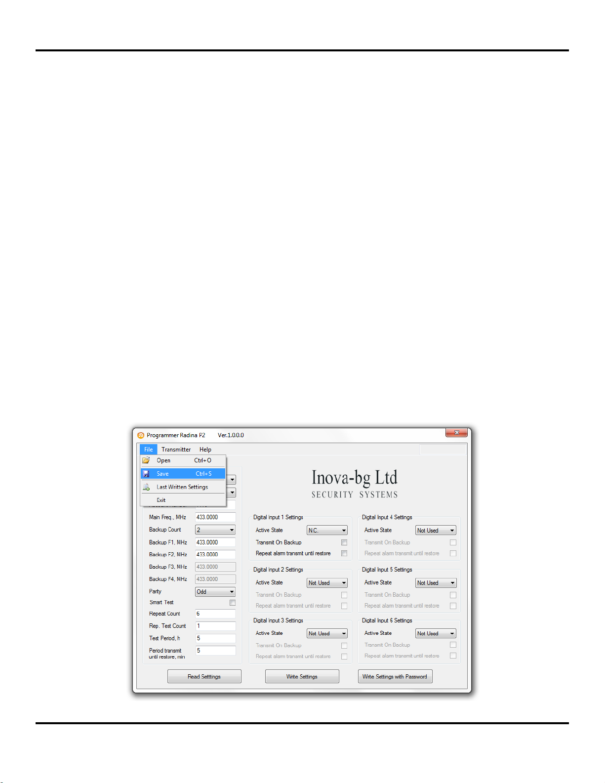
Backup Count –Number of used backups
Backup 1,2,3,4 –Backup frequencies for the radio transmitting. Can be from 400 to 468 MHz
with maximum of four symbols after the decimal point. For each digital input you can choose
whether to transmit or not on the backup frequencies.
Parity –Parity check –Odd or Even.
Use Smart Test –When activated test messages will be sent over a period of time, set by the
field Test Period, and this time will be restarted after every transmitted message regardless if
it’s a test message or not. This option will reduce the number of test messages transmited
through the radio channel. Use this option only if your monitoring software supports it.
Repeat Count –Determines how many times the data message will be transmitted through the
radio channel. Must be from 1 to 15. Default –6.
Repeat Test Count –Determines how many times the test message will be transmitted through
the radio channel. Must be from 1 to 15. Default –1
Test Period –Determines the time period ( in hours ) between test messages. Must be from 1
to 255. Default –5
Period transmit until restore, min –Determines how often ( time period in minutes ) to
repeat the alarm message until the corresponding digital input is not restored. This option can
be enabled separately for each digital input. Default –5
3.2. Settings for the digital inputs
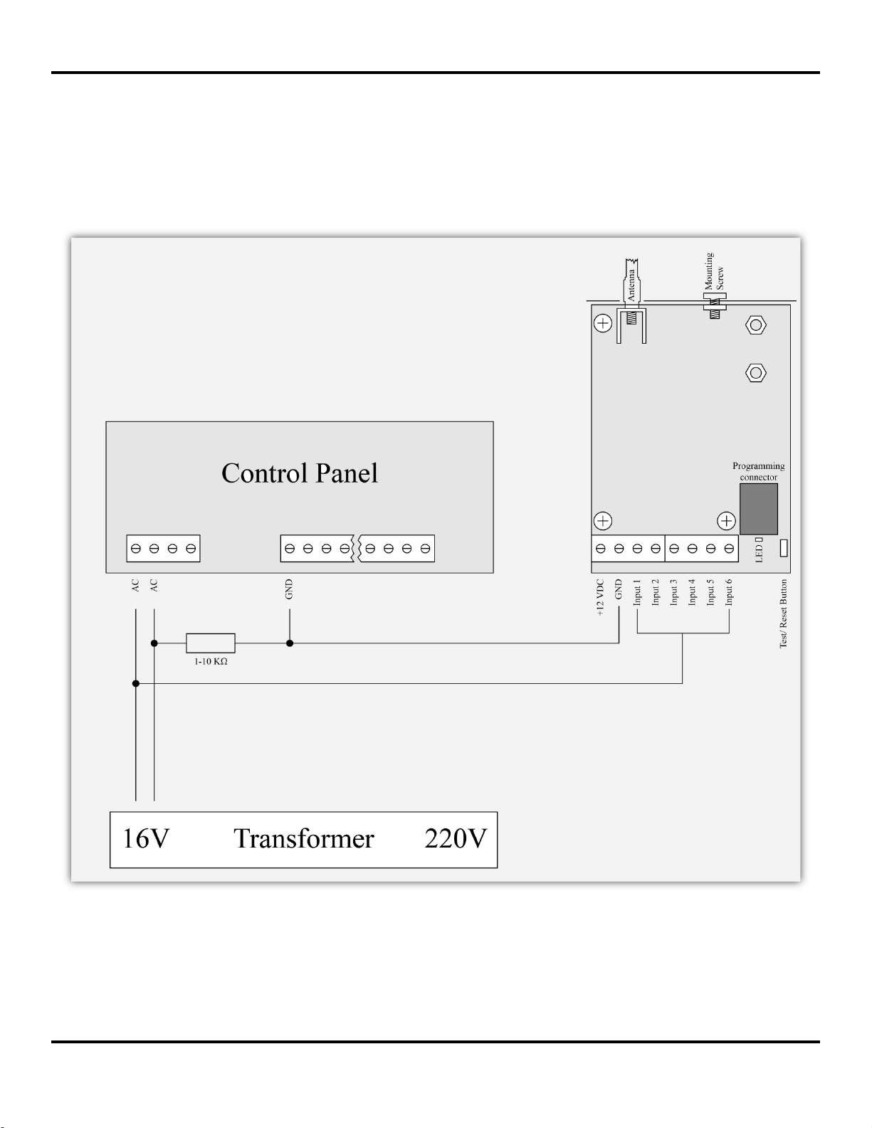
Digital inputs can be connected to PGM outputs of security panles or to any different kind
of sensors –panic-buttons, tampers and etc. In the Active State field you can set the working
mode of each input –normal close ( N.O. ) or normal open ( N.C. ) contact, check for AC on
this input ( Hardware AC ) or you can disable the input ( Not Used ). When digital input is
connected to PGM or dry contact, for ‘0’ state is accepted value of the resistance to ground less
than 300Ω and for active ‘1’ –value more than 1,4KΩ ( or open circuit ), the hysteresis is
between 300Ω and 1,4KΩ. If digital inputs are controlled by voltage for ‘0’ state is accepted
value of the voltage to ground less than 0,7V, and for active ‘1’ –value more than 2,6V, the
hysteresis is between 0,7V and 2,6V.
Radio messages are transmitted through radio channel for each input –A1 to A6 for alarms
on this input and B1 to B6 for restore. For each input you can set the following parameters:
Transmit on backup –Determines whether to send messages for this input on back-up
channel or not.
Repeat Alarm Transmit Until Restore –Determines whether to repeat messages for this
input until it is in alarm state - using the Period transmit until restore, min field to make
pauses between repeats.

Radina U2 User Manual v2.2
Inova-bg Ltd. 2012
Page 7 of 10
3.3. Saving the new configuration
There is two ways to save the configuration on each device - with or without a password. This is
done by the buttons - Write Settings and Write Settings with Password.
Write Settings - If this button is used the device configuration will be saved without a password.
Note: If previously a password is used, it must be entered before saving the new configuration.
Write Settings with Password –If this button is used the device configuration will be saved
with a password. After that, every attempt to read or re-write the configuration will require a
password.
Note: If previously a password is used, it must be entered before saving the new configuration.
If everything is OK, a confirmation window will be displayed.
3.4. Reading configuration from device
This can be done by pressing the button - Read Settings. If previously a password is used, it
must be entered before reading the configuration.
3.5. Open/Save configuration
In the File menu, there is buttons Open and Save.
By pressing the Save button, current configuration can be saved and to be used again very
easy.
With the Open button, a saved configuration is loaded.

Radina U2 User Manual v2.2
Inova-bg Ltd. 2012
Page 8 of 10
4. Hardware reset
In case you changed the settings and can’t reach the device or if you forgot your password,
Radina U2 is capable to return to its factory defaults. For this purpose you must disconnect
from power supply, push and hold the button for hardware reset and reconnect to the power
supply. Hold the button for 5 seconds until the LED is blinking. Once the LED goes off you
can release the button and connect to the device.
5. How to determine the height of the antenna
The height of the antenna is determined by the radio frequency. If you use more than one
radio frequency –make a compromise between all the frequencies. Put the antenna on its place,
remove the plastic cap on the top –start measuring from the end of the box.
Height, cm = 7500 / Frequency, MHz : Lcm = 7500 / FMHz
Frequency FMHz
Formula
Height of the antenna Lcm
400.0000 MHz
7500 / 400
18.75 сm
410.0000 MHz
7500 / 410
18.29 сm
420.0000 MHz
7500 / 420
17.86 сm
430.0000 MHz
7500 / 430
17.44 сm
440.0000 MHz
7500 / 440
17.05 сm
450.0000 MHz
7500 / 450
16.67 сm
460.0000 MHz
7500 / 460
16.30 сm
470.0000 MHz
7500 / 470
15.96 сm
Lcm

Radina U2 User Manual v2.2
Inova-bg Ltd. 2012
Page 9 of 10
6. Hardware AC connection
Each of the digital inputs could be used as a “Hardware AC” input. In this mode it will
monitor the AC and generate a message for “AC Loss/AC Restore”.

Radina U2 User Manual v2.2
Inova-bg Ltd. 2012
Page 10 of 10
7. Mounting in the security panel box
The mounting screw on the top of Radina U2 should be used for proper mounting of the
device in the box of the security panel. The pictures below shows how to use it.
Table of contents
Other Inova Transmitter manuals
Popular Transmitter manuals by other brands

Key Digital
Key Digital KD-IP1080Tx operating instructions

Emerson
Emerson Rosemount 644h quick start guide

PR electronics
PR electronics 5333 Series manual

Perfect Choice
Perfect Choice PC-331117 user guide

Michell Instruments
Michell Instruments Pura 2-Wire user manual

Ecreso
Ecreso HELIOS Series user manual