BG CARDIO ELITE EM X User manual
www.3GCardio.com
CARDIO
3G
®
3G
CARDIO
®
CARDIO
3G
®
3G
CARDIO
®
ELITE EM X
ELLIPTICAL TRAINER
Owner’s Manual

Questions? Call 888-888-7985
3G Cardio • 14647 So. 50th St. Suite 110 • Phoenix, AZ 85044
www.3GCardio.com
CAR DIO
3G
®
3G
CARDIO
®
© Copyright 3G Cardio LLC
All Rights Reserved
IMPORTANT! PLEASE READ:
CARDIO
3G
®
3G
CARDIO
®
3G Cardio Fitness Equipment
14647 So. 50th Street Suite 110
Phoenix, AZ 85044
1-888-888-7985
www.3GCardio.com
support@3gcardio.com
If you purchased your 3G Cardio product from an online retailer (3GCardio.com,
Amazon, etc..) and need help or have questions, comments or concerns, please call or email
us (3G Cardio) directly. We are not operators, we are experienced fitness professionals and
can help you with anything and everything!
If you purchased your 3G Cardio product from a “brick and mortar” retail
store, feel free to contact the store directly with any questions or concerns. You are still
more than welcome to contact us too!

Questions? Call 888-888-7985
3G Cardio • 14647 So. 50th St. Suite 110 • Phoenix, AZ 85044
Welcome to the 3G Cardio Family!
We are a highly experienced team of health and tness equipment experts with over
fty years experience in the health and tness industry. Our two main goals are
to offer outstanding exercise equipment and to provide the best customer service
experience possible.
We understand that you have many choices when it comes to tness equipment. We
know that our continued success is based upon the quality of the products we deliver
and the client support we provide.
We will never cut corners to save money and we will always exceed your expectations!
If you ever have questions, problems or concerns, please contact us right away. We
are fantastic at what we do and we would love a chance to prove it to you.
3G Cardio Family
1-888-888-7985

www.3GCardio.com
CAR DIO
3G
®
3G
CARDIO
®
Table of Contents
Safety Warnings and Precautions 1
Warm Up / Cool Down 2
Assembly Parts 3
Hardware Identication Chart 4
Before You Begin 5
Elite EM X Elliptical Trainer Assembly 6 - 15
Moving Your Elite EM X Elliptical Trainer 16
Console Instructions 17 - 27
Heart Rate Information 28
Bluetooth® Connectivity 29
Maintenance 30
Exploded Diagram 31 - 32
Parts List 33 - 34
Warranty 35

1Questions? Call 888-888-7985
3G Cardio • 14647 So. 50th St. Suite 110 • Phoenix, AZ 85044
SAFETY WARNING
WARNING: To reduce the risk of serious injury, read the following safety
instructions before using this machine.
• Read all warnings posted on the equipment
• Read this Owner’s Manual and follow it carefully before using the equipment. Make sure that it is
properly assembled and tightened before use
• We recommend that two people be available for assembly of this product
• Keep children and pets away from the equipment. Do not allow children and pets to use or play on the
equipment. Always keep children and pets away from the equipment when it is in use
• It is recommended that you place this exercise equipment on an equipment mat
• Set up and operate the equipment on a solid level surface. Do not position the equipment on loose rugs
or uneven surfaces. Do not lean against this machine as it presents a tipping hazard!
• Inspect the equipment for worn or loose components prior to each use
• Tighten / replace any loose or worn components prior to using the equipment
• Consult a physician prior to commencing an exercise program. If, at any time during exercise, you feel
faint, dizzy, or experience pain, stop and consult your physician
• Follow your physician’s recommendations in developing your own personal tness program
• Always choose the workout which best ts your physical strength and exibility level. Know your limits
and train within them. Always use common sense when exercising
• Before using this product, please consult your personal physician for a complete physical examination.
• Do not wear loose or dangling clothing while using the equipment
• Never exercise in bare feet or socks; always wear correct footwear, such as running, walking, or cross-
training shoes
• Be careful to maintain your balance while using, mounting, dismounting, or assembling the equipment
loss of balance may result in a fall and serious bodily injury
• Keep both feet rmly and securely on the Foot Pedals while exercising
• The equipment should not be used by persons weighing over 350 pounds / 158 kgs
• The equipment should be used by only one person at a time
• The equipment is for semi-commercial, light-commercial and home usage
• Maintenance: Replace the defective components immediately and/or keep the equipment out of use
until repair the equipment completely. Maintain the item regularly to make sure that any safety related
features are working properly, replace any components that are dangerous and wearing (such as pedal,
connection areas…etc.) right away.
• Make sure that adequate space is available for access to and passage around the equipment; keep at
least a distance of 1 meter from any obstruction object while using the machine
WARNING: Before starting any exercise or conditioning program you should consult with your personal
physician to see if you require a complete physical exam. This is especially important if you are over the
age of 35, have never exercised before, are pregnant, or suffer from any illness.
!! IMPORTANT VOLTAGE INFORMATION !! Before plugging the power cord into an electrical outlet,
verify that the voltage requirements for your area match the voltage of the machine that you have received.
The power requirements for this machine are: 9V / 1.5 amps. This machine can be plugged into a standard
120v household outlet. The plug must be plugged into an appropriate outlet that is properly installed
and grounded in accordance with all local codes and ordinances. DANGER! Improper connection of the
equipment-grounding conductor can result in a risk of electric shock. Check with a qualied electrician or
service provider if you are in doubt as to whether the machine is properly grounded.
2
www.3GCardio.com
CAR DIO
3G
®
3G
CARDIO
®
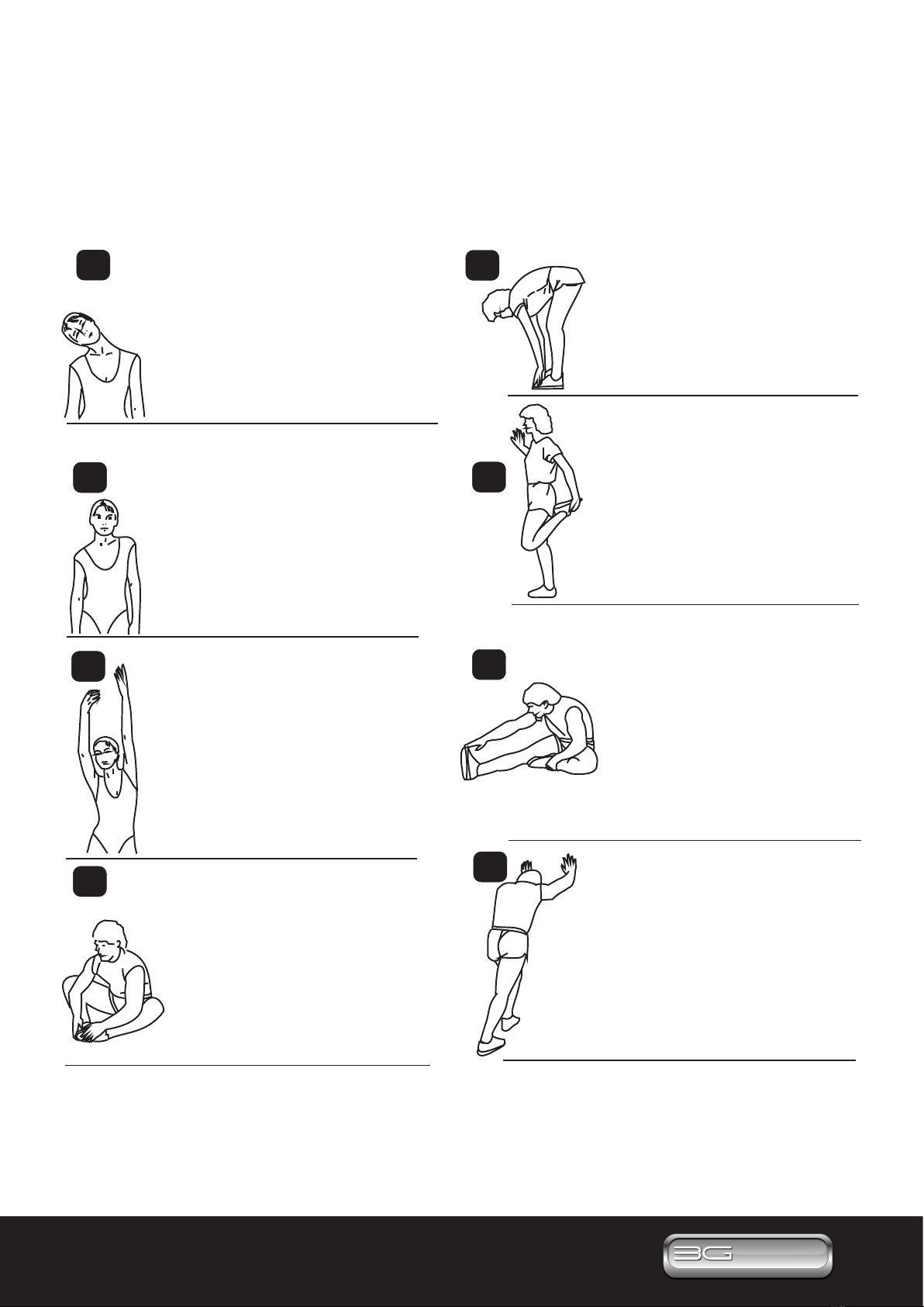
WARM-UP & COOL DOWN
WARM- UP& COOL-DOWN
A successful exercise program consists of a warm up, aerobic exercise, and a cool down. Warming up is
an important part of your workout, and should begin every session. It prepares your body for more
strenuous exercise by heating up and stretching out your muscles. At the end of your workout, repeat
these exercises to reduce sore muscle problems. We suggest the following warm-up and cool-down
exercises:
Head Rolls
Rotate your head to the right for one
count, feeling the stretch up the left
side of your neck. Next rotate your
head back for one count, stretching
your chin to the ceiling and letting your
mouth open. Rotate your head to the
left for one count, and finally, drop
your head to your chest for one count.
Shoulder Lifts
Lift your right shoulder up toward
your ear for one count. Then lift
your left shoulder up for one
count as you lower your right
shoulder.
Side Stretches
Open your arms to the side and
continue lifting them until they are
over your head. Reach your right
arm as far upward toward the
ceiling as you can for one count.
Feel the stretch up your right side.
Repeat this action with your left
arm.
Quadriceps Stretch
With one hand against a wall
for balance, reach behind you
and pull your right foot up. Bring
your heel as close to your
buttocks as possible. Hold for
15 counts and repeat with left
foot up.
Inner Thigh Stretch
Sit with the soles of your feet
together with your knees
pointing outward. Pull your feet
as close into your groin as
possible. Gently push your
knees toward the floor. Hold for
15 counts.
Toe Touches
Slowly bend forward from your
waist, letting your back and
shoulder relax as you stretch
toward your toes. Reach down
as far as you can and hold for
15 seconds.
Calf / Achilles Stretch
Lean against a wall with your
left leg in front of the right and
your arms forward. Keep your
right leg straight and the left
foot on the floor; then bend the
left leg and lean forward by
moving your hips toward the
wall. Hold, then repeat on the
other side for 15 seconds.
1
2
3
4
5
6
8
7
Hamstring Stretches
Sit with your right leg straight in
front of you. Straighten your leg
out while trying to hold on to
your outstretched leg with your
hand. Starting up with your back
straight. Slowly exhale and try
to bring your chest to the knee
of your outstretched leg. Hold,
then repeat on the other side for
15 seconds.
A successful exercise program consists of a warm up, aerobic exercise, and a cool down. Warming up is an
important part of your workout, and should begin every session. It prepares your body for more strenuous
exercise by heating up and stretching out your muscles. At the end of your workout, repeat these exercises
to properly cool down. We suggest the following warm up and cool down exercises:
WARM UP & COOL DOWN

3Questions? Call 888-888-7985
3G Cardio • 14647 So. 50th St. Suite 110 • Phoenix, AZ 85044
ASSEMBLY PARTS
Unpack the box in a clear, open area. Review the List of Assembly Parts below. Check and make sure
all assembly parts are present and in good condition. Do not dispose of the packing material until the
assembly process is completed.
Console
#32 Fixed Handlebar
Tube Cap
#44 & #45 (L & R) Upper Handlebar
#27 Leveler #30 Support Tube #28 Front Stabilizer
#55 Pedal #63 Adaptor (9V / 1.5A) #99 & #36 Swing Arm (L & R) #47 & #48 Pivoting Arm (L & R)
#25 Rear Stabilizer #58 Pedal Support Arm #1 Main Frame
Tub of Grease (For use on Page 10 - Step B)

4
www.3GCardio.com
CAR DIO
3G
®
3G
CARDIO
®
HARDWARE IDENTIFICATION CHART
Review the “List of Hardware Kit” below. This chart is provided to help identify the hardware used during
the assembly process. Place the washers, the end of bolts, or screws on the circles to check for the correct
diameter. Use the small scale to check the length of the bolts and screws.
NOTICE: The length of all bolts and screws except those with flat heads is
measured from below the head to the end of the bolt or screw. Flat head
bolts and screws are measured from the top of the head to the end of the
bolt or screw
HARDWARE KIT Part No. and Description QTY
65 Lock Washer (M8)
3 pcs
66 Washer (8x16x2.0t)
3 pcs
67 Washer (8x30x3.0t)
4 pcs
82 Screw, Pan Head (M5xp0.8x15mm)
4 pcs
85 Bolt, Socket Head (M8xp1.25x20mm)
3 pcs
86 Bolt, Socket Head (M8xp1.25x30mm)
8 pcs
94 Bolt, Socket Head (M8x1.25x25mm)
4 pcs

5Questions? Call 888-888-7985
3G Cardio • 14647 So. 50th St. Suite 110 • Phoenix, AZ 85044
BEFORE YOU BEGIN
Always consult with your doctor to conrm you are healthy enough to begin an exercise program.
THE FOLLOWING TOOLS ARE INCLUDED FOR ASSEMBLY:
Console
Swing Arm
Pivoting Arm
Pull Pin
Transportation
Wheel
Pedal
Front Stabilizer
Pedal Support Arm
Hand Pulse Sensor
Upper Handlebar
MULTI WRENCH TOOL W/
PHILLIPS SCREWDRIVER
(65mm)
ALLEN WRENCH
(6 mm)
SOCKET WRENCH
(17 mm)
Rear Stabilizer
6
www.3GCardio.com
CAR DIO
3G
®
3G
CARDIO
®
ASSEMBLY INSTRUCTIONS
Detailed Lever- drawing 1
Stabilizer
Adjustment
Plate
Leveler (27)
Stabilizer
Adjustment
Plate
Leveler (27)
Detailed Lever- drawing 2
Adjustment
Plate
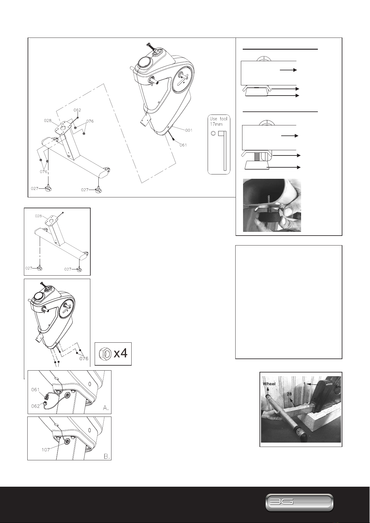
LEVELING NOTE: After placing the
item in the intended location, check the
stability of the item. If the equipment is
not level, review the following
directions:
Loosen the Leveler (27) to make the
Adjustment Plate become less tight.
Use one hand to adjust the Leveler
(27) for leveling.
Once the machine is level, tighten the
Adjustment Plate securely against the
Stabilizer to lock the Leveler (27) as
shown in drawing 2 above.
STEP 1 – Leveler Assembly
A) Follow the drawings to attach 2pcs
Levelers (27) under the Front Stabilizer
(28). Be sure to tighten the Levelers (27)
securely until screw lines are eliminated
as the drawing 1 shows on the top right
corner.
NOTE: If the item is not level, review
the LEVELING NOTE on the right side
of this page.
STEP 2 – Front Stabilizer Assembly
A) Remove 4pcs Nylon Nuts (76) from the
Main Frame (1).
B) Place the Main Frame
(1) on the original packing
Styrofoam.
C) Then attach the Front Stabilizer (28)
(with the wheels face up) to the Main Frame
(1) and fully tighten 4pcs Nylon Nuts
(M10xp1.5)(76).
D) Refer to left, attach the Lower Adaptor
Connection Wire (62) into the Middle
Adaptor Connection Wire (61).
E) Then neatly tuck the wires (61 & 62) into
the hole of the Snap Bushing (107).
7Questions? Call 888-888-7985
3G Cardio • 14647 So. 50th St. Suite 110 • Phoenix, AZ 85044
ASSEMBLY INSTRUCTIONS
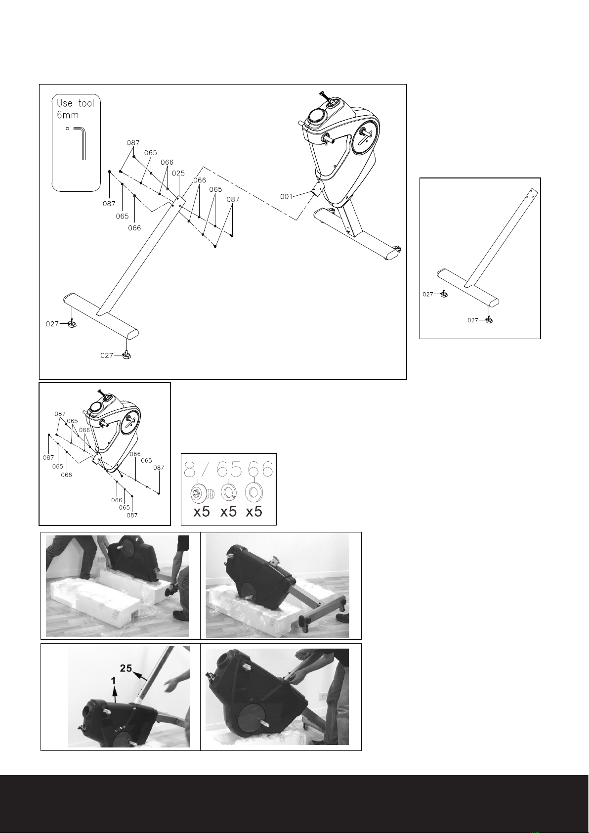
STEP 3 – Rear Stabilizer Assembly
A) Refer to below picture,
attach 2pcs Levelers (27)
under the Rear Stabilizer
(25) and make sure they are
level on the oor.
NOTE: Refer to left picture, 5pcs Washers (8x16x2.0t)(66), 5pcs Lock
Washers (M8)(65), 5pcs Bolts, Button Head (M8xp1.25x16mm)(87) have
been preassembled on the rear of the Main Frame (1).
B) Remove the above bolts and washers from the Main Frame (1).
NOTE: 2 Person Step
C) Refer to the picture on the left,
carefully turn the elliptical over and
place the front main frame onto the
Styrofoam (which originally covered
the front side of the main frame).
Attach the Rear Stabilizer (25) to the
Main Frame (1) and loosely secure
with 5pcs Washers (66), 5pcs Lock
Washers (65), 5pcs Bolt (87). NOTE:
Do not fully tighten the Bolts (87) until
Step 5; part C.
8
www.3GCardio.com
CAR DIO
3G
®
3G
CARDIO
®
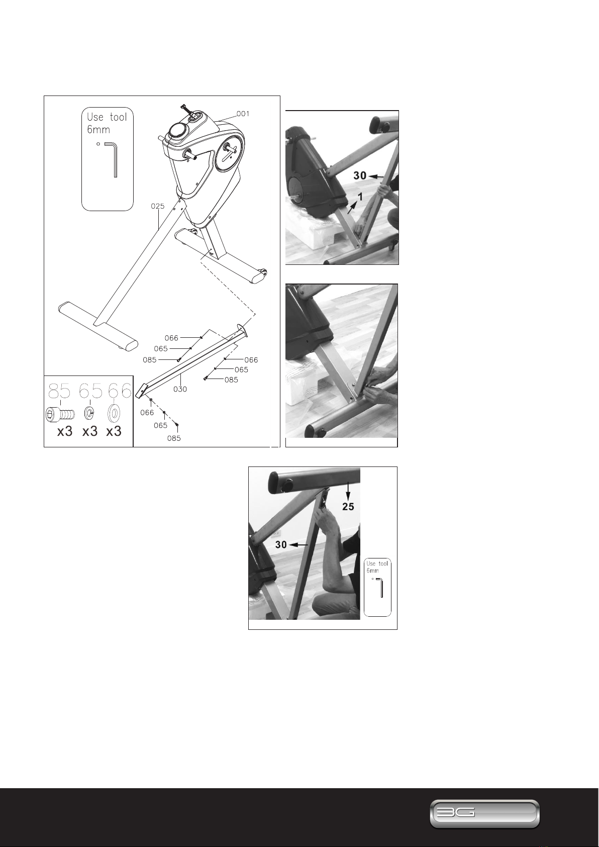
ASSEMBLY INSTRUCTIONS
STEP 4 – Support Tube Assembly
A) Attach the Support Tube
(30) to the Main Frame
(1) by loosely attaching
1pcs Bolt, Socket Head
(M8xp1.25x20mm) (85), 1pcs
Lock Washer (M8 ) (65), 1pcs
Washer (8x16x2.0t) (66).
NOTE: Please do not fully
tighten Bolt (85) until Part A
of Step 5.
B) Loosely attach 1pcs Socket
Bolt (85), 1pcs Lock Washer
(65) and 1pcs Washer (66)
into the bottom of the Support
Tube (30).
NOTE: Please do not fully
tighten Bolt (85) until Part A
of Step 5.
C) Attach Support Tube (30)
to the Rear Stabilizer (25).
Fully tighten 1pc Socket Bolt
(85), 1pc Lock Washer (65)
and 1pc Washer (66) into the
top of the Support Tube (30).
9Questions? Call 888-888-7985
3G Cardio • 14647 So. 50th St. Suite 110 • Phoenix, AZ 85044
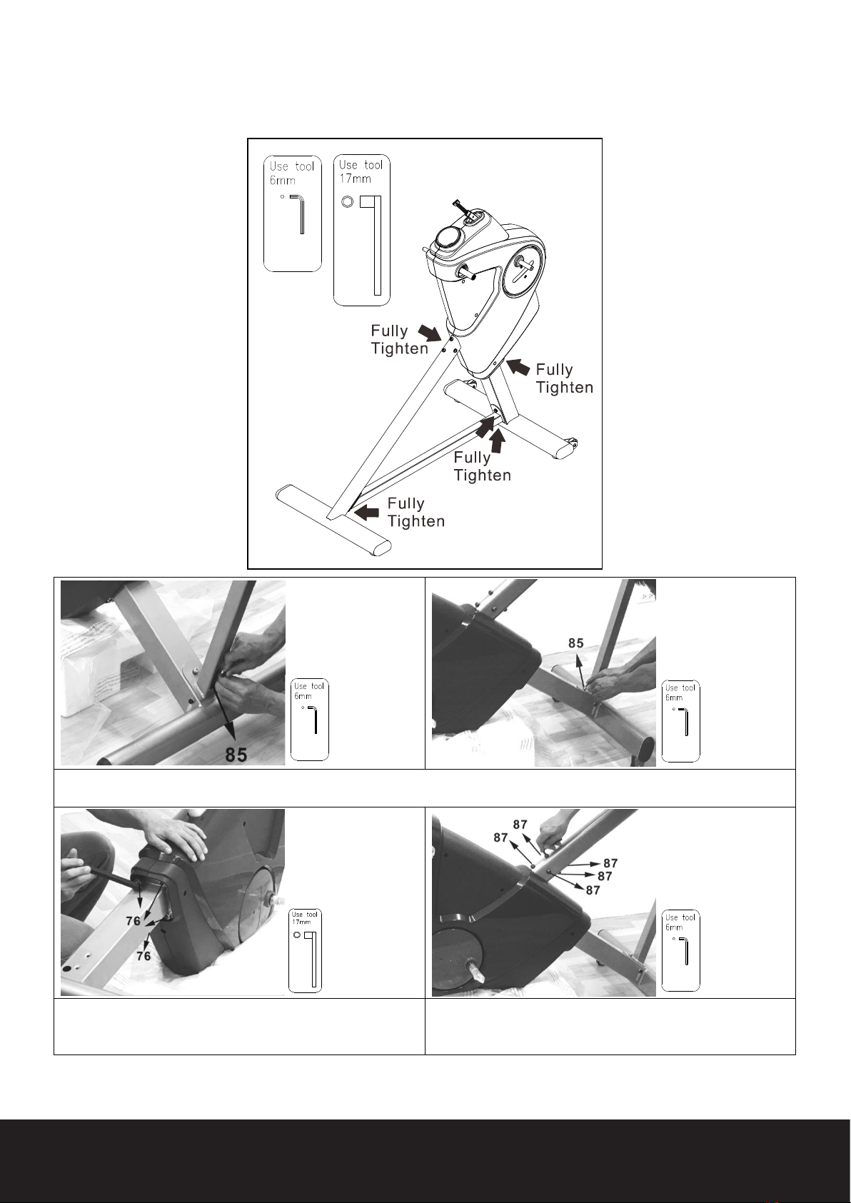
A) Refer to above two photos to go back tothe bottom of the Support Tube (30) to fully tighten 2pcs Socket Bolts (85)
2pcs Lock Washers (65) and 2pcs Washers (66).
B) Go back to the upper side of the Front Stabilizer (28) and
fully tighten 4pcs Nylon Nuts (76).
C) Go back to the front of the Rear Stabilizer (25) and fully
tighten 5pcs Washers (66), 5pcs Lock Washers (65),
5pcs Bolts (87).
ASSEMBLY INSTRUCTIONS
STEP 5 – Tighten All Bolts
A) Refer to above photos. Tighten the bolts at the bottom of Support Tube (30) and fully tighten 2pcs Socket Bolts (85),
2pcs Lock Washers (65) and 2pcs Washers (66).

10
www.3GCardio.com
CAR DIO
3G
®
3G
CARDIO
®
ASSEMBLY INSTRUCTIONS
STEP 6 – Swing Arm Assembly
A) There is an “R” & “L” decal on
the Swing Arm (99, 36).
B) Find the “Tub of Grease” and
open. Apply a small amount of
grease to both Axles (001a and
001b) on both sides. Wipe off
any excess grease after sliding
on Swing Arm and Pivoting Arm.
C) Refer to left, gently
remove plastic packaging
material from two Axles.
NOTE: Be sure not to
remove the washers that
are already installed inside
while removing packaging
material.
D) Refer to left pic, make
sure the Axle surface is
ush with the Bearing
surface before tightening.
E) Slide the Right Swing
Arm (36) onto the Crank
Axle (001a) and fully tighten
1pcs Washer (8x30x3.0t)
(67), 1pcs Tube Cap (35)
and 1pcs Bolt, Socket
Head (M8x1.25x25mm)
(94).
F) Cut the zip tie from the
Swing Arm (36).
G) Repeat the above
procedure for the other side.
Axle
11 Questions? Call 888-888-7985
3G Cardio • 14647 So. 50th St. Suite 110 • Phoenix, AZ 85044
g h
i
j
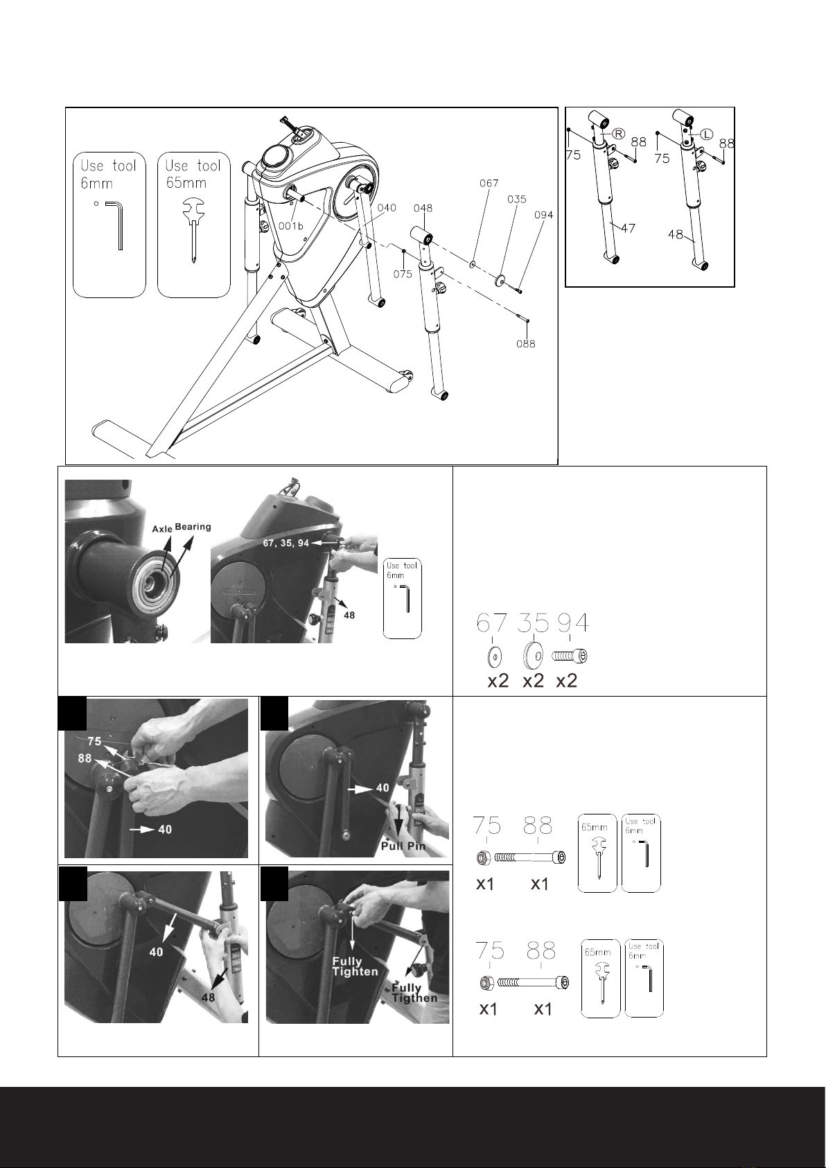
ASSEMBLY INSTRUCTIONS
STEP 7 – Pivoting Arm & Crank Linkage Assembly
A) There is an “R” & “L” decal on the
Pivoting Arm (47, 48).
B) 2pcs Bolts, Socket Head
(M8×p1.25×65mm) (88) and 2pcs
Nylon Nuts (M8xp1.25) (75) have
been preassembled into the Right
Pivoting Arm (48).
C) Remove the above bolts and
nuts before continuing the assembly
process.
D) Refer to left picture, make sure the Axle surface is
ush with the Bearing surface before tightening.
E) Slide the Pivoting Arm (48) onto the Frame Axle
(001b) and fully tighten 1pcs Washer (8x30x3.0t) (67),
1pcs Tube Cap (35) and 1pcs Bolt, Socket Head
(M8x1.25x25mm) (94).
F) Repeat the above same procedure for the other side.
G) Refer to left, in order to assemble the Linkage (40),
rst slightly loosen Bolt (88) and Nylon Nut (75) from
the Crank Linkage (40).
H) Release the Pull Pin (54).
I) Next, attach the Crank Linkage (40) to the Pivoting
Arm (48) and fully tighten 1pcs Bolt (88) and 1pcs
Nylon Nut (75).
J) Go back to Crank Linkage (40) and fully tighten 1pcs
Bolt (88) and 1pcs Nylon Nut (75).
K) Repeat the above procedure for the other side.

12
www.3GCardio.com
CAR DIO
3G
®
3G
CARDIO
®
ASSEMBLY INSTRUCTIONS
STEP 8 – Pedal Support Arm Assembly
STEP 9 – Pedal Assembly
NOTE: Refer above, 4pcs Nylon Nut
(M8xp1.25)(75), 4pcs Bolts, Socket
Head (M8xp1.25x80mm)(89) have been
preassembled on the Pedal Support
Arm (58).
A) Remove above bolts and nuts from
the Pedal Support Arm (58).
Attach the Pedal Support Arm (58) to the Swing
Tube (36) & Pivoting Arm (48) using 2pcs Bolts
(89) and 2pcs Nylon Nuts (75). Tighten fully.
C) Repeat the above procedure for the other side.
A) Put the Pedal (55) on the Pedal Support Arm
(58) and fully tighten 4pcs Bolts, Socket Head
(M8xp1.25x30mm)(86).
B) Repeat the above procedure for the other side.
13 Questions? Call 888-888-7985
3G Cardio • 14647 So. 50th St. Suite 110 • Phoenix, AZ 85044
ASSEMBLY INSTRUCTIONS
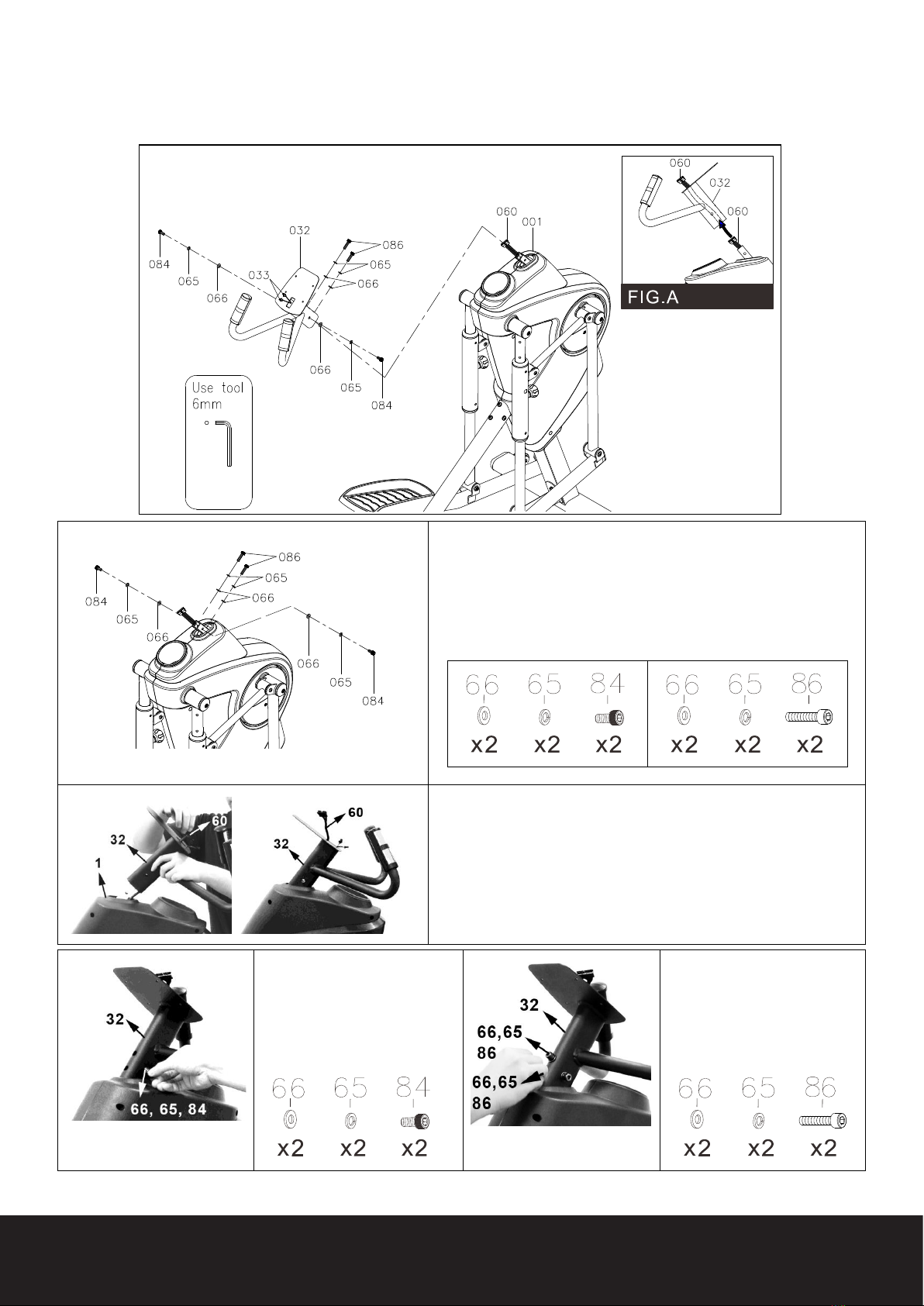
STEP 10 – Fixed Handlebar Assembly
NOTE: See Image on left; 4pcs Washers (8x16x2.0t) (66), 4pcs Lock
Washers (M8) (65), 2pcs Bolts, Socket Head (M8xp1.25x16mm)
(84), 2pcs Bolts, Socket Head (M8xp1.25x30mm) (86) have been
preassembled on the Main Frame (1).
A) Remove these bolts and washers from the Main Frame (1) before
continuing.
B) Follow FIG.A, gently insert the Upper Connection Wire (60) into
the Fixed Handlebar (32).
C) Attach 1pcs Washer (66),
1pcs Lock Washer (65), 1pcs
Bolt (84) on each side of the
Handlebar (32).
NOTE: Please don’t fully tighten
at this time.
D) Attach 2pcs Washers (66),
2pcs Lock Washers (65), 2pcs
Bolts (86) on front side of the
Handlebar (32).
NOTE: Please don’t fully tighten
at this time.
14
www.3GCardio.com
CAR DIO
3G
®
3G
CARDIO
®
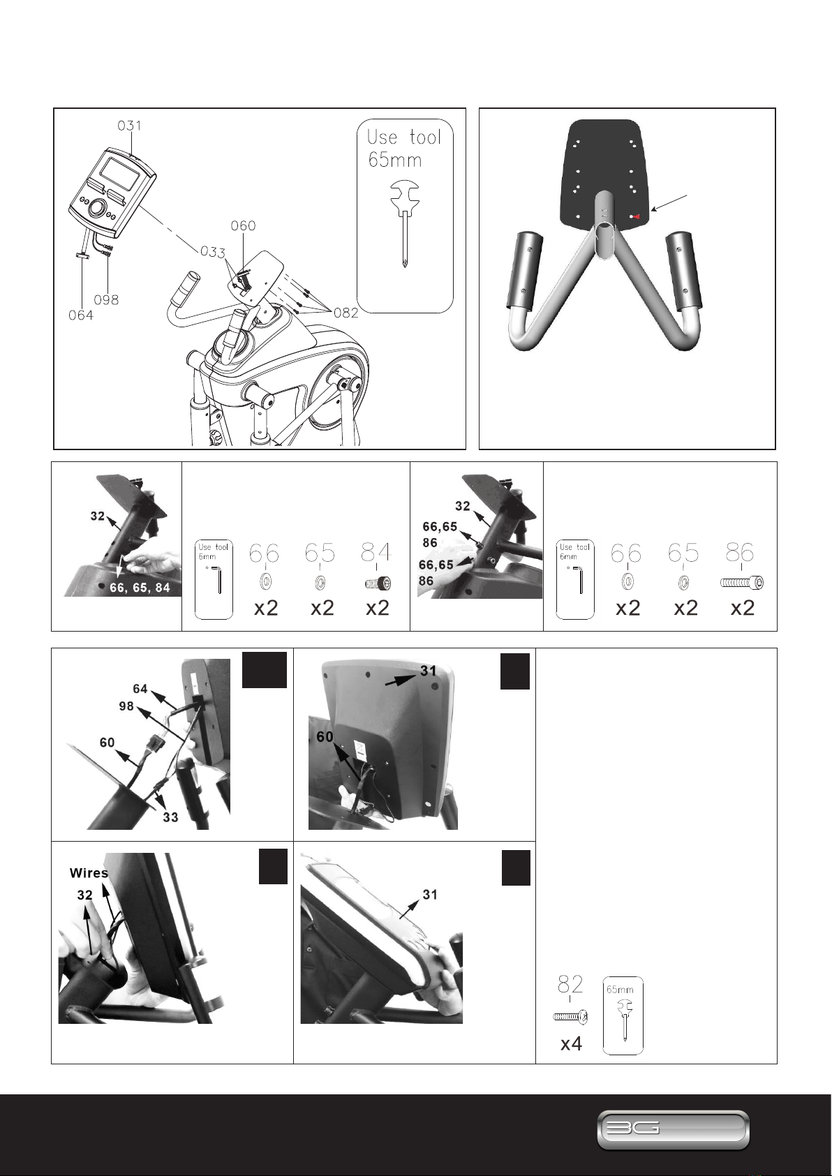
c, d e
f g
A) Go back to the side of Handlebar
(32) and fully tighten 2pcs Washers
(66), 2pcs Lock Washers (65),
2pcs Bolts (84).
B) Go back to the front of
Handlebar (32) and fully tighten
2pcs Washers (66), 2pcs Lock
Washers (65), 2pcs Bolts (86).
C) Connect the Console Wire (64)
to the Upper Connection Wire (60).
NOTE: Be careful not to pinch the
wires.
D) Connect the Console Wire (98) to
the Upper Pulse Sensor Wire (33).
NOTE: Be careful not to pinch the
wires.
E) First slide the Upper Connection
Wire (60) into the Console (31).
F) Then slide the rest of wires into
Fixed Handlebar (32).
G) Follow the above red arrow sticker
to gently attach the Console (31) to
the Fixed Handlebar (32) by fully
tightening with 4pcs Screws, Pan
Head (M5xp0.8x15mm)(82).
NOTE: Refer to the drawing above. To
assemble console in correct position,
rst secure the right bottom corner of
the console to Hole A with Bolt (82).
ASSEMBLY INSTRUCTIONS
STEP 11 – Console Assembly
Hole A
(Red Sticker Hole)
15 Questions? Call 888-888-7985
3G Cardio • 14647 So. 50th St. Suite 110 • Phoenix, AZ 85044
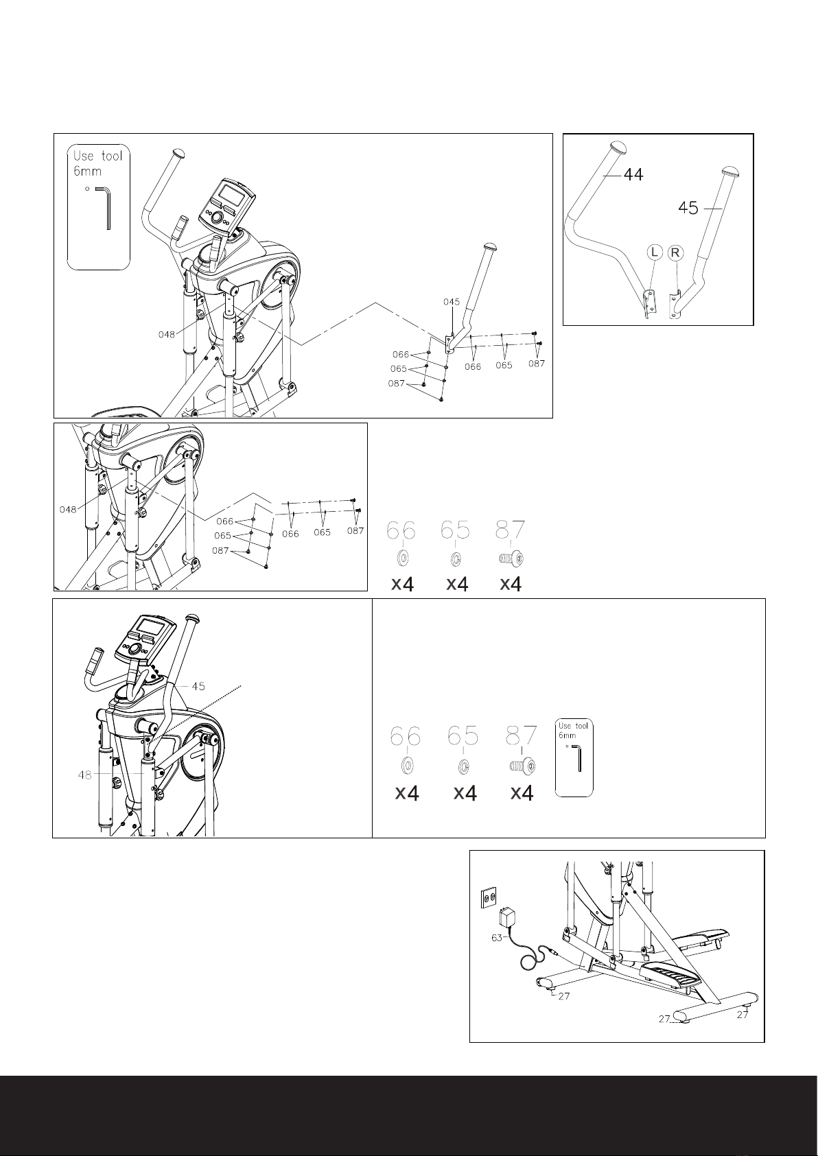
ASSEMBLY INSTRUCTIONS
STEP 12 – Upper Handlebar Assembly
A) There is an “R” &
“L” decal on the Upper
Handlebar (44, 45).
B) NOTE: 4pcs Bolts, Button Head (M8×p1.25×16mm) (87) and
4pcs Lock Washers (M8) (65) and 4pcs Washers (8x16x2.0t) (66)
have already been preassembled into the Pivoting Arm (48).
C) Go ahead and remove these bolts and washers from the Pivoting
Arm (48).
D) Attach the Right Upper Handlebar (45) to the Right Pivoting
Arm (48) and loosely secure with 4pcs Bolts (87), 4pcs Lock
Washers (65) and 4pcs Washers (66).
Once all 4 pcs Bolts (87), Lock Washers (65) and Washers (66)
are in position, fully tighten all Bolts (87), Lock Washers (65) and
Washer (66).
F) Finish the assembly, make sure that all parts are tightened
before you use the equipment.
G) Make sure the item is level on the oor, if not, please
adjust and fully tighten Levelers (27).
STEP 13 – AC Adaptor
A) Connect the Adaptor (63) to the connector located on the
left side of the Main Frame (1).
B) Plug the Adaptor (63) into an electrical outlet to power on
the console.
E) Repeat the above same procedure for the left side.
Fully tighten only
after all 4 pcs
Bolts (87) are in
position.
Table of contents
Popular Elliptical Trainer manuals by other brands


Pro-Form
Pro-Form 420 Zle Elliptical Bedienungsanleitung

Healthstream
Healthstream HS1.0EL user manual

Pro-Form
Pro-Form PFEL13032 user manual

BH Hipower
BH Hipower SK Line SK9300 Instructions for assembly and use

Life Fitness
Life Fitness CPO 91X Specifications

Life Fitness
Life Fitness Elliptical Trainer Manual de operación


