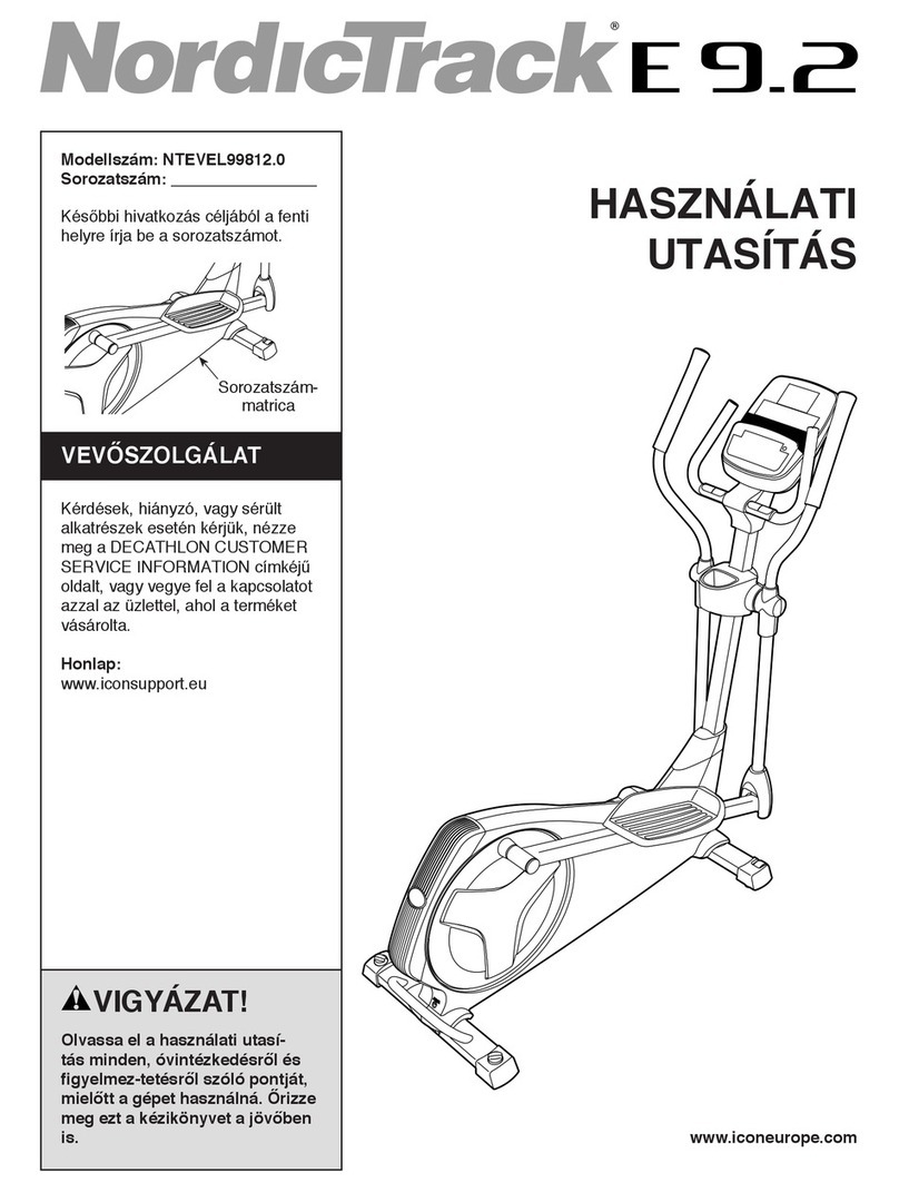
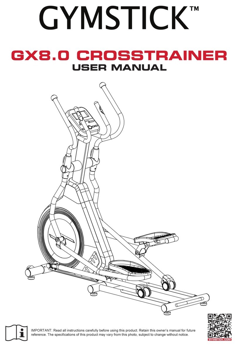
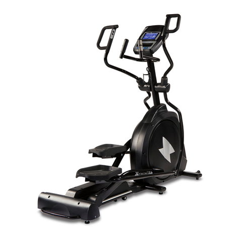
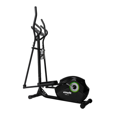
Gymstick PRO20.0 User manual

PRO20.0 CROSSTRAINER
USER MANUAL
IMPORTANT: Read all instructions carefully before using this product. Retain this owner’s manual for future
reference. The specications of this product may vary from this photo, subject to change without notice.

2PRO20.0 CROSSTRAINER
BEFORE YOU BEGIN
Thank you for choosing the Gymstick PRO20.0 Crosstrainer. We take great pride in producing this
quality product and hope it will provide many hours of eective exercise to make you feel better,
look better and enjoy life to its fullest.
TABLE OF CONTENT
1. SAFETY INSTRUCTIONS ................................................................................................ 3
2. EXPLODED DRAWING...................................................................................................... 4
3. PARTS LIST........................................................................................................................ 6
4. ASSEMBLY INSTRUCTION................................................................................................ 9
5. COMPUTER OPERATION INSTRUCTIONS...................................................................... 17
6. MAINTENANCE.................................................................................................................. 23
7 TROUBLESHOOT............................................................................................................... 23
8. IMPLIED WARRANTY......................................................................................................... 24
READ AND FOLLOW THE SAFETY INSTRUCTIONS. FAILURE TO FOLLOW THESE INSTRUCTIONS
CAN RESULT IN SERIOUS INJURY.
!
NOTIFICATION!

3PRO20.0 CROSSTRAINER
!
WARNING!
SAFETY INSTRUCTIONS
Basic precautions should always be followed, including the following safety instructions when using
this equipment: Read all instructions before using this equipment.
1. Keep children and pets away from the machine at all times. DO NOT leave unattended children in the
same room with the machine.
2. Handicapped or disabled persons should not use the machine without the presence of a qualied health
professional or physician.
3. If the user experiences dizziness, nausea, chest pain, or any other abnormal symptoms, STOP the
workout at once. CONSULT A PHYSICIAN IMMEDIATELY.
4. Before beginning training, remove all within a radius of 2 meters from the machine. DO NOT place any
sharp objects around the device.
5. Position the machine on a clear, level surface away from water and moisture. Place mat under the unit to
help keep the machine stable and to protect the oor.
6. Use the machine only for its intended use as described in this manual. DO NOT use any other
accessories not recommended by the manufacturer.
7. Assemble the machine exactly as the descriptions in the instruction manual.
8. Check all bolts and other connections before using the machine for the rst time and ensure that the
trainer is in the safe condition.
9. Hold a routine inspection of the equipment. Pay special attention to components which are the most
susceptible to wear o, i.e. connecting points and wheels. The defective components should be replaced
immediately. The safety level of this equipment can only be maintained by doing so.
10. NEVER operate the machine if it is not functioning properly.
11. This machine can be used for only one person’s training at a time.
12. Do not use abrasive cleaning articles to clean the machine. Remove drops of sweat from the machine
immediately after nishing training.
13. Always wear appropriate workout clothing when exercising. Running or aerobic shoes are also required.
14. Before exercising, always do warm-up and stretching rst.
15. Maximum user weight: 180 kg
BEFORE BEGINNING THIS OR ANY EXERCISE PROGRAM, CONSULT YOUR PHYSICIAN FIRST.
THIS IS ESPECIALLY IMPORTANT FOR INDIVIDUALS OVER THE AGE OF 35 OR PERSONS WITH
PRE-EXISTING HEALTH PROBLEMS.

4PRO20.0 CROSSTRAINER
EXPLODED DRAWING
1
19
42
41
3132
647266
63
97
45
128
96
2120 10 34
4 5
4
7
9
10
8
11
12L
12R
13L
13R
14L
14R
15R
15L
17
18
18
20
20
21 22
22
21
90
24
57
59
58
25
49
27 26
28
29L
29R
30R
30L
34
35
35
34
36
37
39
38
40
43L
43R
44 46
4748
53 46
54 56 55
6
60
64
65
66
65
67
68L 68R
68L68R
73 69 70
16
71
74
7675 77 72
74
78 66
79
80
81 83 82
85
86
84
23
88
9193 89 92
94 95
96
97
97
97
97
33
99
100 101 102 103 104
105
106 107 108 109
111
6261
97
98 97
117
118
96
123
124
50
52
51
121122
96
96
97
125
51
130
52
126127
129
50
97
96
96
5WR23J
131 133132 134
4
147
50
52
51
119
TAICO
Sealed Lead Acid Battery
TP12-2.6(12V 2.6Ah)
Constant Voltage Charge
Standby Use:13.5~13.8V
Cycle Use:14.4~15.0V
Max.lnitial Current:less
than0.78A
135
87
136
137
141 140
143
142
138139
73
7

5PRO20.0 CROSSTRAINER
EXPLODED DRAWING
1
30L&30R
2
19
63
38
118
39
x1
x1
x1
x1
x1
x2
x1
x2
13L&13R
64
&
65
40
x2
68L&68R
x1
x2
x1
x1
x1
x1
x1
14R 15R
&
14L 15L
&
&
12L&12R
11
x1
x1
44
&
45
x1
33
98 99
&
x1
x2
71
87
M12*1.75* 70L 4PCS72 M12*1.75* 12T 4PCS
74
M6*1.0*15 L 8PCS
128
(MM)
M8*1.25*1 20L 4PCS
3
M8*1.25*5 5L 2PCS
147
M8*1.25*7 0L 2PCS
5
D15.4*D8.2* 2T 8PCS
4
D18*D8.5* 1.2T 4PCS
M8*1.25*2 5L 4PCS
119
4
KH-7 47G1
step1
step2
step3
step4
7
7
97
M8*1.25*2 0L 4PCS
6
D24*D13.5 *D2.5T 8PCS73
M8*1.25*5 0L 6PCS
D22*D8.5* 1.5T 6PCS
M8*1.25*8 T 6PCS
8
9
10
step5
M5*0.8*12 L 8PCS97
step6
ST4.2*15L 18PCS
96
M5*0.8*12 L 10PCS97
step7
PART CHECK LIST

6PRO20.0 CROSSTRAINER
PARTS LIST
Part no. Description Specication Q’ty
1 Main frame 1
2Front stabilizer 1
3 Bolt M8*1.25*120L 4
4 Spring washer D15.4xD8.2x2T 12
5 Bolt M8*1.25*70L 2
6 Bolt M8*1.25*20L 4
7 Flat washer D16*D8.5*1.2T 8
8 Allen bolt M8*1.25*50L 6
9Curved washer D22xD8.5x1.5T 6
10 Anti-loose nut M8*1.25*8T 8
11 Handlebar post 1
12L Left movable support welding set 1
12R Right movable support welding set 1
13L Left moving handlebar 1
13R Right moving handlebar 1
14L Left pedal supporting tube 1
14R Right pedal supporting tube 1
15L Left pedal bracket welding set 1
15R Right pedal bracket welding set 1
16 Universal joint 2
17 Foot tube cap 2
18 Crank welding set 2
19 Computer 1
20 Slide beam 2
21 Adjusting round wheel 6
22 Hex nut M10*1.5*8T 6
23 Idle wheel xing plate 1
24 Self-generator 1
25 Crank axle welding set 1
26 Belt wheel 1
27 Belt 520 PJ8 1
28 C at key 8*7*20L 2
29L Left chain cover 1
29R Right chain cover 1
30L Left front chain cover 1
30R Right front chain cover 1
31 Front modied cover 1
32 Upper modied cover 1
33 Rear modied cover 1
34 Round disc 2
35 Side cover 2
36 Rear stabilizer cover 1
37 Rear stabilizer inside cover 1
38 Water bottle holder (front) 1
39 Water bottle holder (rear) 1
40 Water bottle 1
41 Hand pulse cable upper cover 2
42 Hand pulse cable lower cover 2
43L Dip foam(left) 1
43R Dip foam(right) 1
44 Pedals 2
45 Pedal pads 2

7PRO20.0 CROSSTRAINER
PARTS LIST
Part no. Description Specication Q’ty
46 Bearing #6205,2RS,SKF 2
47 Bolt M10*1.5*65L 2
48 Hex nut M10*1.5*8T 4
49 Spacer ring D29.5*D25.2*9T 1
50 Bolt M8*1.25*20L 6
51 Flat washer D25xD8.5x2T 6
52 Buer D27*D8.2*2.5T 6
53 Sleeve D30*D25.2*45L 1
54 Fixing nut M25*1.5*32*6T 2
55 Bolt M6*1.0*10L 2
56 Flat washer D28*D6.5*2T 2
57 Screw M6*1.0*15L 4
58 Flat washer D13*D6.5*1.0T 4
59 Spring washer D10.5*D6.1*1.3T 4
60 Swing axle D25*180.5L 2
61 Roller wheel D70*43 4
62 Bearing 6002 2RS,SKF 8
63 Roller wheel cover 162*136.2*87 2
64 Handlebar cover(front) 240.5*127.8*59 2
65 Handlebar cover (rear) 240.5*127.8*50 2
66 Bearing #60042RS,SKF 12
67 Sleeve(二) D25.4*D20.2*44L 2
68L Front foot cover (left) 152.3*91.1*46.7 2
68R Front foot cover (right) 152.3*91.1*60 2
69 Spacer bushing D29*D12.1*9T 4
70 screened pipe D25.4*D20.2*26L 2
71 Front pedal axle cover 182.4*95.7*67.6 2
72 Bolt M12*1.75*70L 4
73 Flat washer D24*D13.5*D2.5T 8
74 Anti-loose nut M12*1.75*12T 4
75 Bearing #2203-2RS 2
76 C ring S-40(1.8T) D40 2
77 Space bushing D19*D17*D12*20T 4
78 bushing D25.4*D20.2*31L 2
79 Bolt M6*1*15L 8
80 Screw ST4.2*15L 8
81 C ring S-17(1T) 1
82 Waved washer D17*D22*0.3T 3
83 Bearing 6203-2RS ,SKF 2
84 Anti-loose nut M8*1.25*8T 1
85 Flat washer D28*D8.5*3T 1
86 Hex nut M8*1.25*6T 1
87 Sliding beam welding set 1
88 Plastic at washer D50*D10*1.0T 1
89 Anti-loose nut M6x1.0x6T 2
90 Bolt M6*75L 1
91 Fixing sheet 20*27*4T 2
92 Bolt M6x1.0x15L 2
93 Bolt M6*1*5T 3
94 Bolt M8x1.25x20L 4
95 Hex nut M8*1.25*8T 4
96 Screw ST4.2*15L 49

8PRO20.0 CROSSTRAINER
PARTS LIST
Part no. Description Specication Q’ty
97 Bolt M5*0.8*12L 38
98 Computer bracket(front) 1
99 Computer bracket(right) 1
100 Upper computer cable 300L 1
101 Middle computer cable 900L 1
102 Lower computer cable 650L 1
103 Connecting cable 1000L 1
104 sensor cable 500L 1
105 Round magnet 1
106 Upper cable for quick button(1)400L 1
107 Upper cable for quick button(2)400L 1
108 Lower cable for quick button(1)850L 1
109 Lower cable for quick button(2)850L 1
111 control board 1
117 Power cable 620L 1
118 Computer back cover 1
119 Bolt M8*1.25*25L 4
120 Bolt M8*1.25*40L 2
121 Roller wheel 2
122 Spacer bushing D22.2*D8.2*7T 4
123 Screw M3*0.5*30L 4
124 Screw M3*0.5*12L 2
125 End cap 2
126 Buer D21*D8.2*2.5T 4
127 Spacer ring D19*D15.2*25.5L 4
128 Bolt M6*1*15L 8
129 End cap 4
130 Round cap 2
131 Battary connecting cable 1
132 Buer 25*2T*80 2
133 Chargeable battery 1
134 Fixing plate(1) 1
135 Connecting cable(2) 1000L 1
136 Flat washer D15*D5.2*1.0T 4
137 Flat washer D34*D26*2T 1
138 Bolt M8*1.25*20L 4
139 Flat washer D18*D8.5*1.2T 4
140 Computer xed base welding set 1
141 Bolt M10*1.5*75L 1
142 Flat washer D20*D11*2T 1
143 Hex nut M10*1.5*10T 1
144 Pin D6*26.5*7.7 2
145 Screw ST4*1.41*12L 3
147 Bolt M8*1.25*55L 2

9PRO20.0 CROSSTRAINER
ASSEMBLY INSTRUCTION
STEP 1.
1. Assemble the front stabilizer (2) to the main frame (1) with:
• bolt (3)
• at washer (7)
• spring washer (4)
• bolt (5)
2. Assemble the sliding beam welding set (87) to the main frame (1) with:
• bolt (147)
• bolt (3)
• at washer (7)
• spring washer (4)
1
147
4
3 4
step1
4
D15.4*D8.2*2T
5x2
M8*1.25*120L x4
3
x8
M8*1.25*70L
D18xD8.5x1.2T x4
M8*1.25*55L x2
147
4 3
4
5
2
13 19
87
7
7
7

10PRO20.0 CROSSTRAINER
ASSEMBLY INSTRUCTION
STEP 2.
1. Fix the middle computer cable (101) to the lower computer cable (102)
2. Assemble the handlebar post (11) to the main frame (1) with:
• bolt (119)
• spring washer (4)
• at washer (7)
3. Use bolt (97) to the x the rear modied cover (33).
1
4
7
11
119
4
x4
D15.4*D8.2*2T
M8*1.25*25L
119 x4
7
D18xD8.5x1.2T
x4
97 x1
33
97
33
step2
M5*0.8*12L
97
101
102

11PRO20.0 CROSSTRAINER
ASSEMBLY INSTRUCTION
STEP 3.
1. Assemble the left and right movable support welding set (12L and 12R) to the handlebar post (11) with
bolt (6). As shown in gure below.
6
12L
11
12L
12L 12R
11
6
step3
M8*1.25*20L x4
6
x2
ab

12PRO20.0 CROSSTRAINER
ASSEMBLY INSTRUCTION
STEP 4.
1. Assemble the right pedal supporting tube (14R) to the main frame (1) as shown in g 4-1 with:
• bolt (72), at washer (73), anti-loose nut (74)
2. Assemble the right movable support welding set (12R) to the right pedal bracket welding set (15R) with:
• bolt (72), at washer (73), anti-loose nut (74), as shown in gure 4-2
3. Assemble the pedals (44) to the right pedal bracket welding set (15R) with:
• cross bolt (128), as shown in gure 4-3 (a)
4. Assemble the pedal pads (45) to pedals (44) as shown in gure 4-3 (b).
1
14R
12R
72
15R
128
44
15R
73
73
74
72
73
73
74
45
44
step4
x4
x8
M12*1.75*70L x4
72
x8
128
D24*D13.5*D2.5T
M12*1.75*12T
M6*1.0*15L
13 19
73
74
4-1
4-2
4-3
ab
x2
x2
x2

13PRO20.0 CROSSTRAINER
ASSEMBLY INSTRUCTION
10
13L
12L
9
8
13R
12R
8
9
10
5-2
5-1
10 x6
M8*1.25*8T
9x6
M8*1.25*50L
x6
8
D22*D8.5*1.5T
step5
!
!
STEP 5.
1. Assemble the right moving handlebar (13R) to the right movable support welding set (12R), with:
• bolt (8), curved washer (9), anti-loose nut (10) as shown in gure 5-1
2. Assemble the left moving handlebar (13L) to the left movable support welding set (12L), with:
• bolt (8), curved washer (9), anti-loose nut (10) as shown in gure 5-2

14PRO20.0 CROSSTRAINER
ASSEMBLY INSTRUCTION
97
97
118
19
11
97
11
19
11 97
118
step6
6-1
6-2 6-3
M5*0.8*12L
97 x8
STEP 6.
1. Assemble the computer (19), x the upper computer (100) to the middle computer (101), gure 6-1.
• Upper cable for quick button (1) (106) to the lower cable for quick button (1) (108).
• Upper cable for quick button (2) (107) to the lower cable for quick button (2) (109).
2. Assemble the computer (19) to the handlebar post (11) using bolt (97) as shown in gure 6-2.
3. Assemble the computer back cover (118) to the handlebar post (11) with bolt (97), gure 6-3.

15PRO20.0 CROSSTRAINER
ASSEMBLY INSTRUCTION
1
96
39 38
11
65 96
96
64
96
97
30R
30L
97
97
63
7-2
7-3
7-6
x2
x2
step7
7-4
M5*0.8*12L
97 x10
ST4.2*15L
96 x18
96
7-5
x2
x2
7-7
71
7-1
96
98
99
11
97
STEP 7.
1. Fix the computer bracket (front) (98) and the computer bracket (right) (99) to the handlebar post (11),
with screw (96) as shown in gure 7-1.
2. Fix the water bottle holder (front) (39) and the water bottle holder (right) (38) to the handlebar post (11),
with screw (96) as shown in gure 7-2.
3. Fix the handlebar cover (front) (64) to the handlebar cover rear (65), with screw (96), gure 7-3.
4. Assemble the front chain cover (30L&30R) for the main frame (1), with screw (96) and bolt (97), as
shown in gure 7-4.
5. Fix the front foot cover left (68L) to the front cover right (68R), with screw (96), gure 7-5.
6. Assemble the roller wheel cover (63) with 2 pcs bolt (97), gure 7-6.
7. Fix the 2 pcs axle cover (71), with bolt (97), as shown in gure 7-7.

16PRO20.0 CROSSTRAINER
ASSEMBLY INSTRUCTION
STEP 8.
1. Insert the power cord.
2. Adjust the ground wheels at the same height.
step8

17PRO20.0 CROSSTRAINER
COMPUTER OPERATION INSTRUCTIONS
DISPLAY FUNCTIONS
BUTTON FUNCTIONS
ITEMS DESCRIPTION
TIME Setting range: 0:00~99:00 (±1 minute)
Display range: 0:00~99:59
DISTANCE Setting range: 0.00~99.0 (±1)
Display range: 0.00~99.99
CALORIES Setting range: 0~9990 (±10)
Display range: 0~9999
PULSE Setting range: 0~30~230 (±1)
Display range: 0~230
WATTS Display range: 0~999
SPEED Display current working speed, max 99.9
RPM Display current RPM
Display range : 0~999
ITEMS DESCRIPTION
+ Setting or increase the training resistance.
-Setting or decrease training resistance.
ROTARY BUTTON To conrm all setting.
STAR/STOP To start or stop workout.
RESET In setting mode or in selection mode, press to go back to initial training
mode. If keep pressing this button 2s, computer will restart.
RECOVERY To test heart rate recovery status.
BODY FAT To test body fat % when press the BODY FAT button in standby mode.

18PRO20.0 CROSSTRAINER
COMPUTER OPERATION INSTRUCTIONS
OPERATING MANUAL
Power on
1. When powering on the device, the LED-display will display all segments, such as wheel diameter, KM or
ML, Eurasian gauge. (Image 1 & 2)
2. Enter into user selection mode, setting user’s private le U1-U4 (image 3), GENDER (image 4), AGE
(image 5), HEIGHT (image 6), WEIGHT (image 7). After setting the information, device will enter into
function selection mode: MANUAL, PROGRAM, USER PROGRAM, H.R.C, WATT.
Image 1. Image 2.
Image 3. Image 4.
Image 5. Image 6.
Image 7.
Power o
If without RPM input for 4 minutes, LED-display will be closed and the computer will be in power o -mode.
If RPM is detected again, the computer will wake up.

19PRO20.0 CROSSTRAINER
COMPUTER OPERATION INSTRUCTIONS
MANUAL FUNCTION
By turning buttons “+” or “-” , user may set up TIME > DISTANCE > CALORIES > PULSE (image 8 - 10).
Press START/STOP without settings to start a workout, and in working period the user can adjust the
RESISTANCE LEVEL. Press START/STOP again and the computer will enter into break mode, press button
“RESET” to leave this mode.
PROGRAM FUNCTION
In this mode, there are 12 programs (P1~P12) for the user to select (image 11). When the user chooses
a PROGRAM, by turning buttons “+” or “-”, can be set the TIME (image 12). When nished setting press
“START/STOP” to start workout (in break mode the user can choose to adjust the “TIME” value). In START
status, user can adjust RESISTANCE level. During workout, press “START/STOP” and the computer will
enter into break mode, press “RESET” leave this mode.
Image 8. Image 9.
Image 11. Image 12.
Image 10.

20PRO20.0 CROSSTRAINER
COMPUTER OPERATION INSTRUCTIONS
PROGRAM FUNCTION
All the dierent programs are shown below (P1-P12).
USER PROGRAM FUNCTION
By turning buttons “+” or “-” , the user can set PROGRAM, then press MODE/ENTER to conrm the setting
value of RESISTANCE (image 13). If the user wants to stop the setting, keep pressing MODE/ENTER
button for 2 seconds, LED-display will show last value set. While pressing MODE/ENTER button for 2
seconds, the user can set “TIME” (image14), if no value is set, press “START” to enter into working mode. In
START mode user can adjust the resistance. During the workout press “START” to enter into break mode,
then press button “RESET” leave this mode.
P1
P5
P9
P3
P7
P11
P2
P6
P10
P4
P8
P12
Image 13. Image 14.
Other manuals for PRO20.0
4
Table of contents
Other Gymstick Elliptical Trainer manuals