BGB S2 User manual

1
S2 eBike Display Manual
Light Indicator
USB Power On
Brake Indicator
Battery Charge Percentage
Battery Charge Level
Error Warning
Current Speed
Average Speed
Max Speed
Speed
KPH or MPH
Power | Trip
Odometer | Time
Value
Peddle Assist Indicator
Display Icon Information
Brake Indicator: This icon appears to advise that the brake has been engaged and power to the motor has been
disabled.
USB Power On: Confirms if USB port is powered and ready for use.
Light Indicator: Confirms the lights are turned on and dims the display for night riding.
Current Speed: Real-time actual speed information.
Average Speed: Your average speed for this ride.
Max Speed: Your maximum speed travelled this ride.
Peddle Assist Indicator (PAS): Displays the current level of power assistance, where 0 is neutral and no power and
where 1 - 9 corresponds to power assist level. 1 is low, 9 is high.
Error Warning: The system has detected an error.
Battery Charge Percentage: 100% - The battery is fully charged. 0% indicates the battery is empty and requires
charging.
Battery Charge Level: This level is based on your riding style and optimised by a range algorithm. The display learns
how you ride and provides battery level information based on this data.
Speed preference: KPH or MPH
Mileage display: 'POW' - Power output from the motor. 'Trip' - distance travelled this ride. 'ODO' - odometer, total
accumulated mileage. 'Time' - Time elapsed since the system powered on.

Keypad Function
Power On/Off: Long press the POWER button for about 1 to 3 seconds to turn the system on. Long press the power
button for about 1 to 3 seconds to turn the system off.
Mileage Display: Short pressing the POWER button scrolls through the ODO, Trip, Time and Power data
Odometer Time Trip Motor Power Output
PAS Levels: Pressing the PLUS button or MINUS button will increase or decrease the level of assistance. The lowest
being 0 (neutral and no power) up to 9 being maximum power. By default, the system has 5 PAS levels.
*PAS - Peddle assistance levels
PAS 0 PAS 3 PAS 9
'+' PLUS button
'i' MODE button '-' MINUS button
POWER button
2

AVG (Average speed)
Speed Information: Short pressing the POWER button scrolls through the AVG (Average speed), MAX (maximum
speed) and SPEED ( real time speed)
MAX (Maximum Speed) SPEED (Real Time Speed)
Walk Mode (6 kph): Press and hold the MINUS button to use walk mode.
USB Function: Long press (1 second) the MODE button to turn on the USB port located at the bottom of the display.
Great for charging for phone - DC 5V max 500ma.
USB ONUSB OFF
Clear logs: Press the PLUS and MINUS button for 1 second to clear average, max, trip and time data.
3

When the display is turned on, press the MODE button twice (<0.3 seconds between presses). This will enter the settings menu.
Press the MODE button twice to exit the setting menu. (<0.3 seconds between presses). When in the setting state, press MODE
button to select the desired adjustment, when the parameter flashes, press PLUS button and MINUS button to adjust the parameter
setting. Press POWER button to save and move to the next parameter. Press MODE button twice to exit the setting state (<0.3
seconds between presses).
*if no key operation is performed for 30 seconds, the display automatically exits the setting state. In the riding state (the speed
indication is not 0), you cannot enter the setting interface. If you start cycling in the setting interface (the speed indicator is not 0),
you will automatically exit the setting.
Default
Setting
BGB Recommended
Description
P1
4
4
Screen brightness 1 through 5 with 1 = DIM 5 = BRIGHTEST.
P2
5
5
Auto-shutdown (represented in minutes) - 1 minute through 9 minutes or OFF. To save power, the system
can shut down automatically or not at all. Select, how long the system remains on when the bicycle is not
being used before shutting down.
P3
0
1
Distance - 0 = KPH or 1 = MPH.
P4
0
0
Automatic gearing - DO NOT CHANGE.
P5
1801
1801
Advanced Menu (Password 1801)
A1
48
48
System Voltage = 48v - DO NOT CHANGE
A2
5
5
PAS levels - 3/5/6/9.
A3
99
25
Speed limit in KPH. 25 = UK on-road limit. 100 = no speed limit
A4
15
5
Current/Power limit. 5 = UK on-road limit. We do not recommend increasing above 15 when off-road.
A5
24
24
Wheel circumference - 16/18/20/22/24/26/27/700C/28/29/30/31/32. You can change this setting to
improve the accuracy of the speed reading.
A6
1
1
Number of speed measuring magnets - DO NOT CHANGE
A7
12
12
Number of PAS magnets - DO NOT CHANGE
A8
0
0
Throttle control. 0 = limited to 6 kph. 1 = Unlimited (Ensure A10 is set to 2 to enable the throttle)
A9
0
0
PAS Orientation - DO NOT CHANGE
A10
2
2
0 = PAS only. 1 = throttle only (see A8 for additional throttle settings). 2 = PAS and throttle enabled.
A11
0
0
PWM (Pulse Width Modulator) duty cycle - DO NOT CHANGE
A12
5
0
Initial power produced when starting. For a gentle start use 0. For maximum starting power use 5.
Settings Menu
WARNING
CHANGING CERTAIN SETTINGS WILL VOID YOUR WARRANTY AND
COULD DAMAGE YOUR BIKE.
4

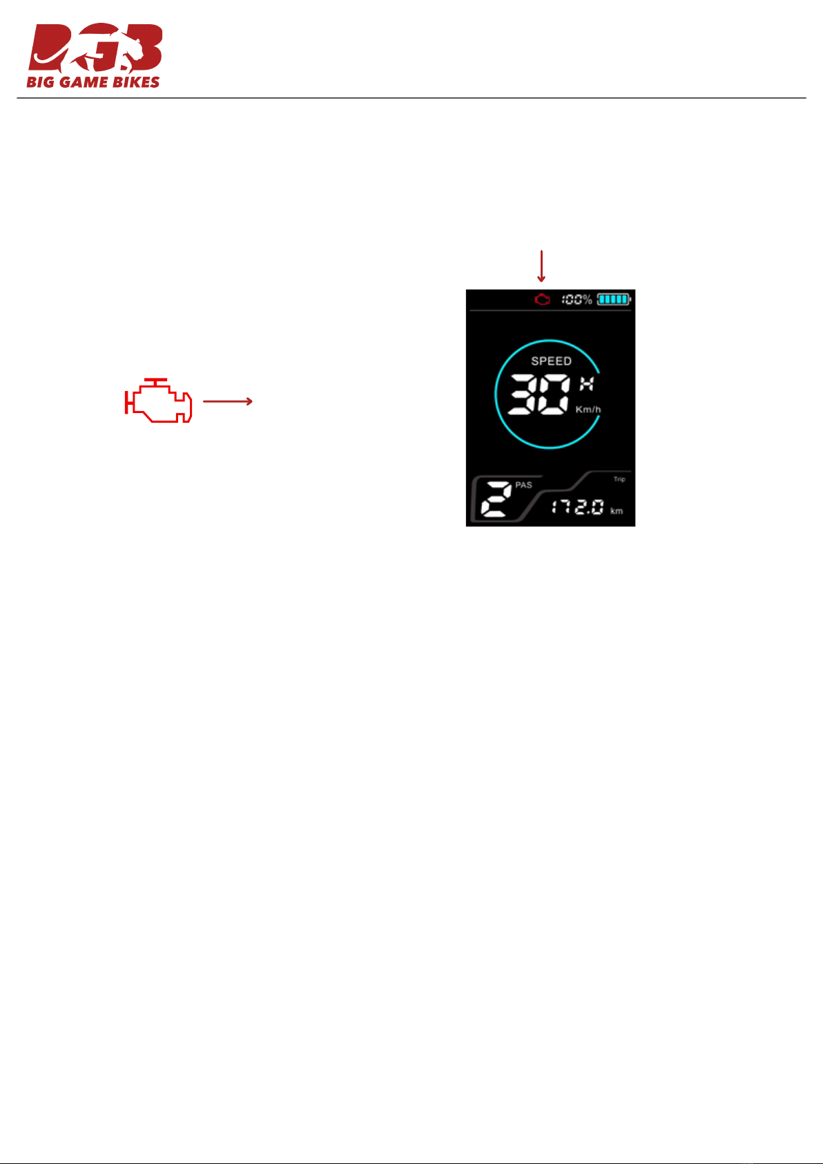
The display can provide error indications for faults. When a fault is detected, the LCD screen displays an 'engine warning type
symbol', and the error code “n” and error description are displayed at the speed display position. Please refer to the error code
comparison table to determine the corresponding fault.
Error Code Definition
'engine warning type symbol'
5
Error Code
08H
40H
20H
10H
30H
Possible Problem
Battery under voltage
Motor fault
Handlebar fault
Controller fault
Communication fault
Solution
Charge the battery
If the Hall of the motor is faulty, check whether the Hall wire
is short-circuited and whether the plug is plugged in
properly. If all are good, replace the motor.
Check the wiring and plug of the handle, if all are good,
replace the handle.
Controller is damaged, replace the controller.
1. Check the display wires for breaks.
2. Check whether the connection between the controller and
the instrument plug is in good condition.
3. Unplug the PAS sensor to see if an error is reported. If no
error is reported, the sensor is short-circuited and damaged,
and the sensor needs to be replaced.
4. Unplug the switch to see if an error is reported. If no error
is reported, the handlebar is short-circuited and damaged,
and the handlebar needs to be replaced.
5. Unplug the motor hall wire to see if an error is reported. If
no error is reported, the motor Hall is short-circuited and
damaged, and the motor needs to be replaced.
6. If the above methods cannot solve the problem, use the
replacement method to troubleshoot the problem: replace
the controller or instrument to troubleshoot which problem
is.
Table of contents