www.dero.com | 1-888-337-6729
© 2015 Dero
96”
72”
32”
32”
Approx.
4.25”
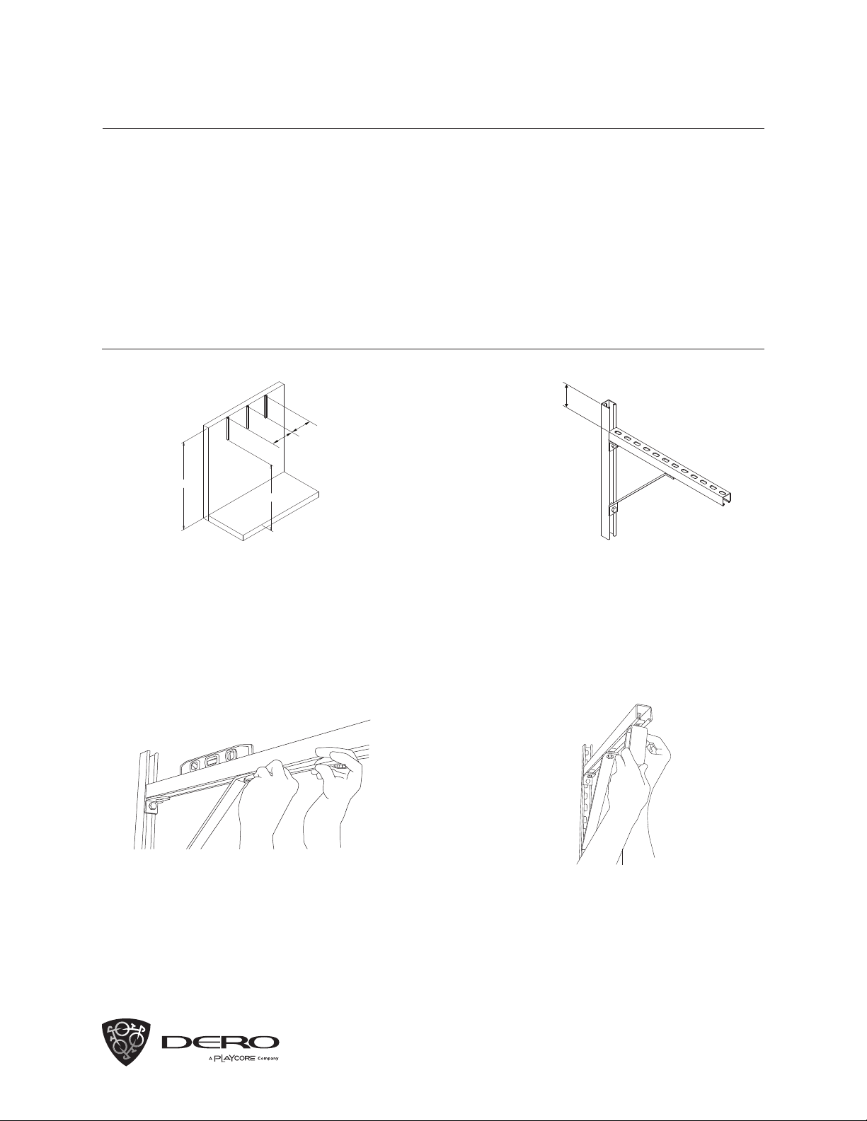
Mount 24” Slotted Tracks vertically to the wall with
the appropriate anchors. Use a level for greatest
accuracy. The bottom edge of the Slotted Track
should be approximately 72” o the floor. The
Slotted Tracks should be 32” apart from each
other, and the end Slotted Tracks should be
18” from the eventual position of the end of the
Trolley track.
Make sure the horizontal Slotted Track is level.
Adjust if necessary.
Mount the remaining 24” Slotted Tracks
horizontally and protruding from the wall so that
the slotted surface of the Slotted Track is 4.25”
below the top edge of the vertical 24” Slotted
Track. Use the Knee Braces, Angle Brackets,
and the Spring-loaded Nuts and Hex Head Cap
Screws to secure the horizontal Slotted Track
in place.
1
3 4
2
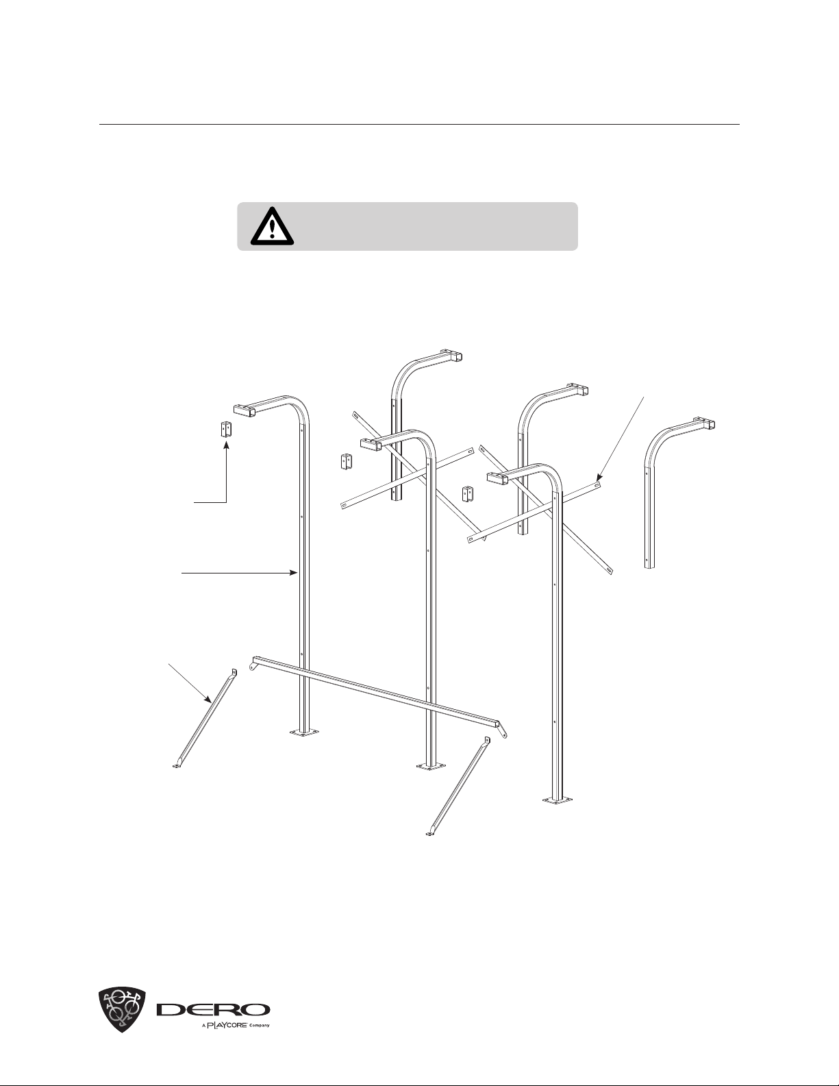
Attach the Bike File to the Wall Mount
assemblies by securing the Channel Trolley
Supports to the horizontal 24” Slotted Track
with the remaining Spring-loaded Nut and Hex
Head Cap Screw. The edge of the Slotted
Track Mounting Bracket should be flush with
the edge of the 24” Slotted Track.
RECOMMENDED BASE MATERIAL
Before installing: Make sure the wall is strong enough to
accommodate the rack fully loaded with bikes. Compare parts
shipped with rack to parts list. Call Dero if any parts are missing.
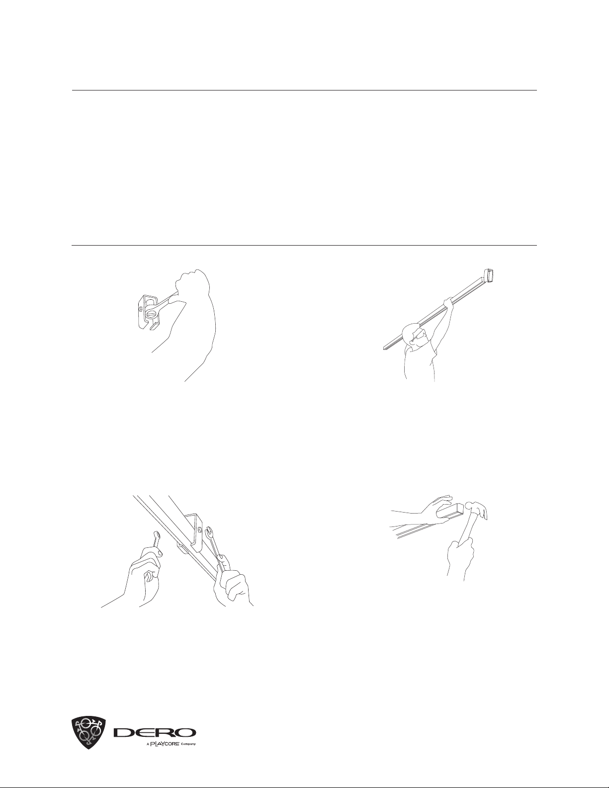
TOOLS NEEDED
9/16” Wrench/Socket
3/4” Wrench/Socket
1/4” Drill Bit or 3/8” Masonry Drill Bit
(depending on anchor type)
Tape Measure
Drill (Hammer Drill Recommended)
Hammer
Level
Saw for cutting rack
BIKE FILE
Installation Instructions – Wall Mount