BGU HBG 100-2 User manual

USER’S MANUAL
Carefully read these instructions before operating
your wood bundler!
WOOD BUNDLER
HBG 100 - 2
Südharzer Maschinenbau GmbH
Helmestraße 94 ∙ 99734 Nordhausen/Harz
Zentrale: 03631/6297-0 ∙ -111
Internet: www.bgu-maschinen.de
e-mail: [email protected]
Manufactured
in Germany
- Set-up & in
stallation
- Use
- Maintenance
- Accessories

2
CONTENTS
1. Introduction
1.1 About the manual
1.2 Delivery and transport claims 3
1.3. Mandatory application field 4
2. Safety signs and decals 5
3. Safety 6
4. Loading 7
4.1 Use of the strapping machine (Art. No.90116, accessory) 7
5. Assembly 10
6. Tipping over the basket 11
6.1 Installation of the cylinder 12
7. Repairs and maintenance 13
7.1 Consumables 13
8. Technical data 13
9. Handling and transportation 14
10. Dismounting and discarding an obsolete machine 14
11. Legal warranty 15
12. Extended warranty 15
13. EC-Statement of compliance 19

3
1. INTRODUCTION
Dear customer,
thank you for buying our log bundler model HBG 100 - 2 and joining
the number of our best customers in the world. We are confident that
our equipment will be up to all your expectations and assure you a
long lasting quality and performance.
1.1 About the manual
Please take time to read this manual and learn to how operate and
maintain the bundler safely. For your easier reading this manual is
laid out in several sections. The sections are progressively numbered
and listed on the “content” page.
The information, pictures and technical data in this document reflect
current or planned product features, functions, and characteristics as
of the publication date. Because of on-going product improvements
and feature additions, information in this document is subject to
change without notice.
If you are experiencing a problem or functional trouble on your ma-
chine, please read the “trouble-shooting” section to identify possible
causes and remedies. If the problem or functional trouble is not listed
in the troubleshooting chart contained in this manual, ask your Autho-
rized Service Centre for service.
When you have checked all the possible causes listed and you are still ex-
periencing the problem, ask your Service Centre for help.When you or-
der parts maintenance or repair services, your Authorized Service Cen-
tre, your dealer or eventually the manufacturer need your machine serial
number and engine serial number. These are the numbers that you have
recorded on the product identification label of the manufacturer on the
machine.
1.2 Delivery and transport claims
Upon delivery of the machine please check for visual machine dama-
ges
such as damaged packing or scratched buckled parts. If so, make
a remark on all copies of the delivery bill before signing for accep-
tance.
Also have the truck driver sign al copies of the delivery bill.
Should your shipper or the truck driver refuse to accept your claim,
fully reject delivery and make sure to inform us (the manufacturer)
immediately. No claims shall be taken into account by the shipper or
by the insurance company, if a reservation note is not made on the
delivery bill.

4
All transport damages must be notified within latest 2 days from delive-
ry. Therefore delivery must be collected and inspected within this
term. Later claims shall be disregarded.
In case of assumed but not visually clear transport damages make sure
to mark the following sentence on the delivery bill: „Reserved delive-
ry due to assumed transportation damages.“
Insurance and shipping companies act with extreme caution in case
of transport damages and sometimes refuse to accept responsibility.
Please make sure to provide clear and exhaustive evidence (photos)
of the claimed damages.
Thank you in advance for your help and understanding in this matter.
1.3. Mandatory application field
This log bundler is designed for firewood wrapping and should not be
used for any other application than that. Loading and unloading with
the tractor through a Euro Quick Coupler is not possible.
Any other use is considered by the manufacturer as “misuse”. In case
of misuse the manufacturer will not be liable for any injuries or dama-
ges and the operator will be held entirely responsible.
Please make sure to comply with these set-up, operation and
maintenance/repair instructions in order to avoid happening of any
injury or dangerous condition.

5
1. Identification label „BGU-Maschinen“ logo“
2. Identification label „Product identification“
This label shows the company details of the manufacturer
and the main technical data of the machine.
3. Machine safety label „Read, understand, and follow
all instructions in this manual and on the bundler before
starting“ Keep at safety distance from the dangerous zo-
ne!!
2. SAFETY LABELS AND WARNING SIGNS

6
Make sure than no person is allowed within the dangerous zo-
ne of the machine! (DANGER while tipping-over and unloading
the bundle)
Do not alter the construction of the machine for no reason whatsoever!
Always make sure that the bundler is safely and efficiently attached to
the tractor and check the conditions of the locking and guarding de-
vices. PTO shields and guards are important safety features that can
prevent serious injury and death. There are instances where the PTO gu-
ard must be removed, and though it is time consuming, the guards and
shields should always be reinstalled before operating the machinery.
While transporting the machine drive carefully and adjust speed to the
type of ground and to the load, if available.
Worne-out, defective, missing and damaged parts must be replaced-
strictly with other original parts!
The user shall strictly comply with these operation, set-up, mainte-
nance, repair and troubleshooting instructions in order to assure safe
operation and no damages to the equipment. Moreover we recommend
to let the machine be run only and strictly by trained and skilled staff
who must be familiar with the applicable occupational safety and health
administration rules as well as applicable transportation rules. Incorrect
use of the splitter can cause serious injury or death. Make sure that full
compliance is assured at all times with the general safety and health
rules on the workplace as well as the applicable local traffic rules.
No person under school leaving age of 18 should operate a wood bund-
ler. However, young people in age of 16 or slightly more may work on
the machine providing that they received adequate training, that they
carry all due personal protection safeties and that an adult supervisor
keeps standing nearby.
Machine instability can result in injury or severe damages. To ensure
stability during operation make sure to choose a flat, dry floor free from
any tall grass, brush or other interferences.
The working area around the machine must be kept as clear as possib-
le from surrounding tripping obstacles and slippery foundation floors
should be avoided. Dress for safety. Wear close fitting clothes and steel-
toed safety shoes. Der Arbeitsplatz um das Holzbündelgerät bzw. Make
sure that all access ways are properly maintained so that wood can be
safely delivered, loaded and shipped.
3. SAFETY

7
Before stacking wood into the basket, make sure that the clamping
mechanism is engaged and the basket secured against twisting (see
Fig.1).
Insert 2 nylon ropes near the steel bunks (select the rope diam. bet-
ween 25, 30, 50 or 100 depending on the size of the wood sticks).
Tie a simple knot on the ends (1) and slip the other rope (2) past the
winch!
Logs must be stacked uniformly into the basket well-fi tting the curved
bunks that cradle the logs and prevent them from rolling.
Tie a knot with both ends (1) and the loose rope (2). Now, operate the
winch crank to stretch the ropes and to lace up the knots
!
As soon as „strapping“ is completed, cut the ends (2) and make a
simple knot to secure the rope!
4. LOADING
Fig. 1
Fig. 2
2
1
11
2
3
4.1 Use of the strapping machine (Art. No. 90116, accessory)
1. Take the open end of the polyester band (90118) and arrange it
around the wood stack.
2. Make a loop at the end of it, push it through the middle of the
steel buckle
a
nd insert it into the buckle from the left side (Pos. 4,
Fig.3) (Art. No.90119).
3. Make another loop (5, Pos.3) on the other end of the polyester
band (on the spool) and again make it slip through the middle of
the steel buckle. Finally, insert the other end of the buckle into this
second loop.
Manually stretch the Band (5, Pos.4) by pulling slightly in the
direction of the arrow.
Fig. 3
Fig. 4
45
45

8
4. Shift the strapping machine „Spanngerät Profi“ laterally underneath
the band and push the lever down to stop and clamp it (see Fig. 4).
Fig. 4
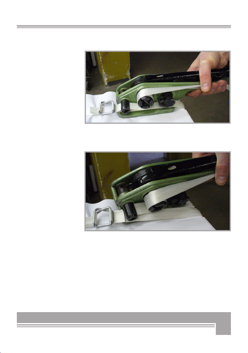
5. Lift the lever up and fit the upper band through the cutter and in
the clamping claw as shown in fig. 5.
Fig. 5
Operate the lever several time up and down to stretch the band com-
pletely.
Fig. 6
9
6. Now, quickly press the lever handle down to cutt the band (as
shown in figure 7)
Fig. 7
6. Remove the stretching machine pulling it out from one side
(Fig.8) and repeat the procedure.
Fig. 8

10
Connect the bundler to the tractor by means of the special 3-point
hitch. Insert the fixation pins and secure them using the respective
cotter pins.
Make sure that the bundler never stands on the front leg only, when
used at maximum load.
The upper hitch point must be conveniently adjusted so that the ma-
chine always stands on all legs.
Failure to comply with this instruction, major damages may
occur to the basket!
To mount your HBG bundler on a front loader (see Fig. 9), you need a
Euro Quick Coupler. Eventually, the latter can be also mounted to the
3-point hitch.
For bundler installation on a front loader, the wood bundles may also
stacked on top of each other. To do so, you need to a special hydraulic
cylinder for the tipping over of the bundles. (see point 6 ).
Drive the tractor/loader up, so that the pin holes of the loader’s draft
arms are nearly aligned with the lower hitch pins of the Euro Quick
Coupler and then raise the draft arms up. (Fig. 9)
Secure with the hitching pins and security clips.
Connect the hydraulic hoses to the adapter of the tractor.
5. ASSEMBLY
Fig. 9

11
6. TIPPING OVER OF THE BASKET
The bundler can be also operated by means of the hydraulic cylinder
(Fig.10).
The hydraulic cylinder is optional and is supplied on request
against payment of an extra charge (Art. No. 90211) .
When operating your bundler through the cylinder, please note:
Before switching the bundler on, remove the locking mecha-
nism for manual drum operation. Failure to do so, may lead to
out-shifting of the cylinder and severe damages to the bundler
and its Euro Quick Coupler.
After complete hydraulic connection, the HBG bundler is ready for
operation by means of power takeoff from the tractor.
A special control valve is provided for laterally tipping over of the bas-
ket.
For bundlers without cylinder, the locking machanism can be manual-
ly controlled to tip over on both sides.
Fig. 10
6.1 Optional Euro Quick Coupler
Additional accessories and aids :
• Poyester textile band (1, Art. No.90118)
• Nylon rope (2, Art. No. 90203)
Fig. 11
1
2

12
• After completing above step one, secure the bottom end of the
cylinder to the special plates using 95 mm long bolts Ø 20mm (central
bore for locking bolts), a Starlock spring Ø 20mm, a flat washer A 21
and a locking bolt (Fig. 13)
• Now connect the hydraulic hose (1.35m)
• First of all you need to secure the cylinder on top to the
special plate using a 95 mm long bolt Ø 20mm (center bore),
a flat washer A 21, a Starlock spring Ø 20mm and a locking bolt
(Fig. 12)
6.2 Installing the (optional) cylinder
Before starting to assemble the machine, the manual crank lever for
tipping over the basket must be dismounte (see point 6, page 11).
Fig. 12
Fig. 13

13
Technical Data HBG 100-2
Log length/firewood capacity 33/50/100 mm
Length 1215 mm
Width 1280 mm
Height 1400 mm
Weight 230 kg
All technical data in this manual may be changed by the manufacturer
even without notice as a result of implementation and quality upgra-
de.
7. REPAIRS AND MAINTENANCE
Before starting to work with your bundler, visually check the machine
to assess the presence of eventual missing parts or defects.
Using original spare parts for your machine will not only help you avo-
id costly production downtime, but also allows you to obtain a produc-
tion in line with our safety and operating specifications.
Make sure to perform timely periodical lubrication of all bearings on
the machine.
Radial thrust bearings are to compensate the unavoidable production-
related range of tolerance. Lubrication of radial thrust bearings is
NOT required, as the thrust function is only used once at the time of
assembly, which means that the existing lubricant film will remain on.
7.1 Consumables
The machine is equipped with the following consumable parts for
• Hydraulic hoses (must be replaces every 4-5 years)
• Bearings
8. TECHNICAL DATA

14
When the bundler is fully obsolete and cannot be of any longer use, it
should be duly dismounted ahead od discarding. Certain components
need deactivation and dismantling in order to assure that no further
use is made by other parties and that no worn out parts are recycled
for other applications.
During dismantle be alert for possible recyclable materials and compo-
nents that belong to differentiated waste collection procedures appli-
cable in your country.
The manufacturer is not liable and undertakes no responsibilities for
personal injuries or damages that may result from the recycling of
worn out machine parts for eventual re-use in other applications diffe-
rent than the originally stated in this manual.
Dismantling procedure:
Take good note please: each and every dismantling task must be per-
formed by authorized service centers or trained skilled staff only!
● Lock and clamp all moving machine parts and pull the machine into
single components
● Deliver each single component only to authorized waste manag-
ment facilities
● Drain oil and fuel out of respective tanks and lines before disposal of
the machine
● Remove rubber and plastic parts from the machine that must be se-
parately disposed of.
Deactivated, clamped moving/driving parts and components are of no
further risk and danger.
Electric components must be separately disposed to avoid substantial
environmental threat. In the event of the fire on the electric deploy-
ment system of the machine, use an explosion-proof extinguish sys-
tem is required (for example powder fire extinguishers).
10. DISMOUNTING AND DISCARDING AN
OBSOLETE MACHINE
9. HANDLING AND TRANSPORTATION
The firewood bundler can be handled as described under Section 6 of
this manual either on the 3-point hitch of your tractor or on a front
end loader.
The bundler attaches both in the front and in the back of a tractor by
means of Euro Quick Coupler.

15
11. LEGAL WARRANTY
All BGU machines are covered with legal warranty. Customers should
promptly notify eventual material, production or workmanship claims
on their detection. While asking for warranty service, customers
should show copy of their purchase invoice or receipt. The warranty
does not cover for faults due to natural wear, temperature or weather
agents as well as misuse, faulty installation or improper lubrication.
No warranty will be given on parts damaged by improper handling or
wrong connections. No warranty applies for cases of major force or
of misuse (for example modifications of the machine or customized
installations done by the customers or unauthorized thirds). No war-
ranty is given in case of machine overload.
Consumable parts (pads, wedges and general materials) as well as
adjustment and/or setting and retrofitting services are not included in
this warranty.
12. EXTENDED WARRANTY
All SŰMA equipment is covered with 24 or 12 months total warranty
from the date of purchase for private/industrial users and rentals.
The total warranty does not substitute nor void the legal warranty.
Customers should promptly notify eventual material, production or
workmanship claims on their detection. While asking for warranty ser-
vice, customers should show copy of their purchase invoice or receipt.
Buyer’s address and type/model of equipment must be clearly stated
in the case of industrial users/contractors/dealers. All claims related
to material or production failures during the total warranty time, shall
be repaired notwithstanding eventual user’s faulty/wrong operation or
maintenance.

16
We hereby declare that the equipment described in this manual responds in full to the actual version
brought on the market. We, the manufacturer further declare that this equipment was duly designed
and manufactured in accordance with the actual European Safety and Health Standards settled by the
relevant EEC directives as well as the latest electromagnetic standards issued by the European Council
of 3.5.89 and later enforced by all member states. This statement of compliance does not apply to
customer modifications of the equipment without manufacturer’s written approval.
Date Jörg Kernstock (Director)
Official user‘s language: English (User‘s release)
Nordhausen 19.07.2010
Machine type: Firewood bundler
Models: HBG 100 - 2
Production No.: see Machine Identification Plate
Applicable European Standards: EC Machine Directive 42/2006
EC Low Voltage Directive (93/68 EWG) 2006/95/EG
EC-EMV
(ElectroMagnetic Compatibility)
Directive 2004/108
Person responsible for the technical documents: Jörg Kernstock (Director)
to the EC Machines Directive No. 2006/42 and EMV (Low Voltage) Directive 2004/108
13. EC – STATEMENT OF COMPLIANCE
Südharzer Maschinenbau GmbH
Helmestraße 94 ∙ 99734 Nordhausen/Harz
Service-Tel. 03631/6297-104 ∙ Fax 03631/6297-111
Internet: www.bgu-maschinen.de
e-mail: [email protected]

17

18

19

Südharzer Maschinenbau GmbH
Helmestraße 94 ∙ 99734 Nordhausen/Harz
Service-Tel. 03631/6297-104 ∙ Fax 03631/6297-111
Internet: www.bgu-maschinen.de
e-mail: [email protected]
Subject to changes without previous notice
Form: 2066.19.07.2010 - Rev. A
Table of contents
Other BGU Industrial Equipment manuals


Popular Industrial Equipment manuals by other brands


Lincoln industrial
Lincoln industrial 85250 Owner's/operator's manual

ABB
ABB HT578977 Operation manual

Siemens
Siemens SENTRON VL1250 operating instructions

Command access
Command access MLRK1 Series Insert Instructions

Multitel
Multitel MX 250 USE AND WARNING INSTRUCTIONS

BVA Hydraulics
BVA Hydraulics FT102 instruction manual