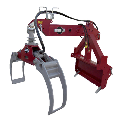
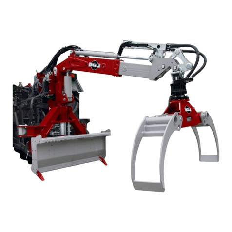
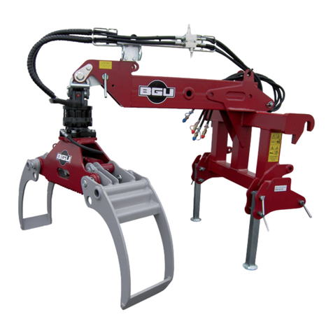
BGU HRZ Kombi Anbau User manual

USER‘S MANUAL
Carefully read these instructions before starting
and using your grapples!
Logging Grapples
Attachment
HRZ Kombi Anbau
We manufacture in
Germany
Start-up
Operation
Maintenance
Accessories
Südharzer Maschinenbau GmbH
Helmestraße 94 ∙ 99734 Nordhausen/Harz
Zentrale: 03631/6297-0 -111
Internet: www.bgu-maschinen.de
e-mail: [email protected]

2
CONTENTS
Contents 2
1. Introduction 3
1.1 About the manual 3
1.2 Delivery and transport claims 3
2. Safety pictograms and warning labels 5
3. Safety 7
3.1 General safety rules and occupational safety 9
4. Operation 10
4.1 Mandatory application field 10
4.2 Attaching the grapple arm to an implement 10
4.3 Start-up 11
5. Hydraulic system 12
6. Repairs and maintenance 13
6.1 Services to be provided at 10 hour operation intervals 13
7. Handling and Transportation 13
8. Accessories 14
9. Technical data 15
10. Disabling and disposal 16
11. Other areas of possible dangers 17
11.1 mechanical dangers 17
12. Warranty 17
13. Spare parts for HRZ Kombi-Anbau 18
14. EC Statement of Compliance 23

3
Dear customer,thank you very much for your trust and preference in
buying this loader!
1.1 About the manual
Please take time to read this manual and learn to how operate and
maintain the splitter safely.
For your easier reading this manual is laid out in several sections. The
sections are progressively numbered 1 through 14 and listed on the
“contents” page.
The information, pictures and technical data in this document reflect
current or planned product features, functions, and characteristics as
of the publication date. Because of on-going product improvements
and feature additions, information in this document is subject to
change without notice.
If you are experiencing a problem or functional trouble on your equip-
ment, please read the “trouble-shooting” section to identify possible
causes and remedies.
When you have checked all the possible causes listed and you are
still experiencing the problem, ask your Authorized Service Centre for
help.
When you order parts maintenance or repair services, your Authorized
Service Centre, your dealer or eventually the manufacturer need your
machine serial number. These are the numbers that you have recorded
on the product identification label of the manufacturer on the machine.
1.2 Delivery and transport claims
Upon delivery of the machine please check for visual machine damages
such as damaged packing or scratched buckled parts. If so, make a re-
mark on all copies of the delivery bill before signing for acceptance.
Also have the truck driver sign al copies of the delivery bill.
Also have the truck driver sign al copies of the delivery bill. Should
your shipper or the truck driver refuse to accept your claim, fully re-
ject delivery of the machine and make sure to inform us (the ma-
nufacturer) immediately. No claims will be taken into account by the
shipper or by the insurance company, if a reservation note is not ma-
1. INTRODUCTION

4
de on the delivery bill.
All transport damages must be notified within latest 2 days from de-
livery. Therefore delivery must be collected and inspected within this
term. Later claims will be disregarded. In case of assumed but not vi-
sually clear transport damages make sure to mark the following sen-
tence on the delivery bill: „„Reserved delivery due to assumed
transportation damages.“
Insurance and shipping companies act with extreme caution in case of
transport damages and sometimes refuse to accept responsibility. Ple-
ase make sure to provide clear and exhaustive evidence (photos) of
the claimed damages.
Thank you in advance for your help and attention to this matter.

5
1. Pictogram: „Grapple Release/Grasp“
2. Pictogram „Hydr. Motor“
3. Pictogram „Boom Lift UP/DOWN“
4. Machine safety label „Read the instructions be-
fore start-up“
Read, understand, and follow all instructions in this manual before
starting!
5. 10. Production label „Product identification“
This label shows the company details of the manufacturer and the
main machine technical data.
6. „BGU-Maschinen“ Manufacturer's logo
2. SAFETY PICTOGRAMS AND WARNING LABELS
HRZ Kombi - Anbau
Südharzer Maschinenbau GmbH
Helmestr.94 99734 Nordhausen
Maschinentyp:
922
Maschinennr: 13 41
Holzrückezange - Anbau
Bezeichnung:
Bj. 13

6
7. Safety pictogram „Do not infringe the dange-
rous zone“
Avoid standing in the dangerous zone between the tractor and the log
loader.
8. Safety pictogram
„Danger Pinch Point“
Keep hands away from this danger zone till all moving parts have
come to a complete stop.
9. Safety pictogram
„Caution : operating zone“
Stand clear : do not allow bystanders in the dangerous operation area
while the machine is at work.
10. Safety pictogram
Max operating pressure

7
Strictly perform installation, set-up, maintenance, cleaning
and transportation with the unit switched off and all moving
parts firmly secured against accidental operation. Immedia-
tely disconnect power off the machine in case of any eventual
faults or troubles.
The user shall strictly comply with these operation, set-up, mainte-
nance, repair and trouble-shooting instructions in order to assure
safe operation and avoid damages to the equipment. The owner must
understand these instructions and must allow only persons who un-
derstand these instructions and are familiar with the related risks to
operate the loader. Moreover we recommend to let the machine be
run only and strictly by trained and skilled staff who must be familiar
with the applicable occupational safety and health administration rules
as well as applicable transportation rules. Incorrect use of the splitter
can cause serious injury or death.
No person under school leaving age (18) should operate this log split-
ter. Those who have reached school leaving age but are below the age
of 16 may operate a log splitter if supervised by a competent person
of 18 years or over. The machine shall be installed and kept in a sui-
table location selected by the customer for safest operation.
Make sure that the equipment stands on a safe stable foundation.
Do not allow within the hazardous zone any unauthorized third or per-
sons who are not familiar with the dangers related to use and opera-
tion of the machine. Allow no bystanders, especially children and pets
in the working area.
• Log loaders are not designed for passengers transportation.
• Strictly control/operate the log grapples from the
driver‘s seat on the tractor.
Do not allow any thirds in the dangerous zone.
The dangerous zone includes the swivel/rotation area as well as the
bucket and grapples operation (grasp/release) area.
Provide due clearance around the log/timber handling zone.
• Make sure to firmly close the clamp and park it across travel
direction when at rest.
• Make sure that the grapple is hanging free so that swinging
to both sides is possible during travel on uneven
ground/terrain.
3. SAFETY RULES

8
• When you pull/hand timber always keep in mind that lurching or
other sudden, flicking movements of a suspended/pulled load may oc-
cur due to timber flexibility and bounciness.
Mind for the safety of your fellow workers safety and take due measu-
res to keep the work area free from other thirds and obstacles.
Maintain safe distances from other ground workers and equipment
units.
• Perform logs piling and general rolling operations with extreme care
and at very low tractor speed.
DANGER: watch for timber/branches that may fall on or enter the
operator’s compartment.
• Immediately repair or replace eventual faulty hydraulic components.
• Do not let hydraulic pressure hoses lay unprotected in the driver‘s
cabin after installing and connecting the control valve unit
(control slide valve / electric valve).
• Always wear suitable protective gloves when doing works on the
hydraulic system. AVOID HAND CONTACT with hydraulic oil.
• BEWARE: a log grapple attached to a U-joint cannot be firmly
laid down on ground. To avoid grapples from rolling over or getting
tangled,make sure to secure it before laying down.
• Before replacing or servicing the grapple hanger, secure the clamp
against fall-over and make sure to strictly grasp the clamp from the si-
des. DANGER of legs/feet injuries.
• Pinch points will occur any time when converting from fixed to mobile
grapple attachment. BEWARE: injured fingers danger.
• If you are using a winch, account for a dangerous area same
as at least the length of the rope. Keep this area free
from bystanders and unauthorized thirds.
• A rescue/emergency kit for drivers and team safety are mandatory
and must be always available in the driver‘s cabin.

9
3.1 General safety rules and occupational safety
• Before each new use, check for your tractor operational and road
travel safety!
• Mind for all safety pictograms and operation labels on your grapple
loader. They are all-important for safe operation and travel!
• Before starting with loading operations, familiarize with all safeties
and controls on your equipment and with their functions. Do not ex-
pect to learn as you practice. Grapple loaders are heavy-duty equip-
ment requiring preliminary training!
• Operators must wear steel toe safety shoes and snug-fitting, tear-
resistant work cloths.
• Keep the front of the gate area as free as possible to avoid fire
danger!
•
Know where crew members are at all times!
Be alert to unexpected
workers or operations in the immediate working area.
•
Before starting the tractor and beginning to work, make sure that there
are no bystanders (especially children) in the surroundings. Be cautious
of blind spots around the loader where the operator’s visibility is limited!
• Sitting on the loader during work or travel can be very dangerous.
Take measures to prevent it.
• Connect the equipment in compliance to these instructions and the
applicable provisions!
• Never overload a machine. Carry a load that is safe, within the ca-
pacity of the machine, and suitably secured in the special fixation
points on the machine!
• Always comply with the admissible axis loads and transport
dimensions/clearance!
• Never leave the operator‘s stand during travel!
• Travel, steering and braking performance are affected by the use
of hanging ballast on the machine. Always keep at safe distance for
steering and braking!
• When taking turns please mind for both the outreach and/or rota-
ting mass of the equipment!
• Make sure that all safeties and protections are duly in place and
operating before starting to use your equipment!
• Strictly start log loading operations when all workers are clear of the area!
• Keep the turning/swaying area of the equipment clear from any
obstacle!
• Make sure that no persons and no obstacles are within the slew
range before operating any of the hydraulic folding frames.
• Before leaving the tractor, make sure to lower the grapple down on
ground, switch the motor off and remove the keys from the ignition!
• Make sure that no persons stand in the dangerous zone between
the tractor and the trailer unless due measures were taken to prevent
the vehicle from rolling away (for example engaging the parking bra-
kes and using additional wheel chocks for increased safe)!
• Folded frames and telescoping hoisting devices must be dulysecured
in the transport position!

10
4. OPERATION
4.1 Mandatory application field
Grapple loaders are strictly designed for wood lot owners to pull, hand-
le and manipulate timber logs.
This grapper loader HRZ Kombi-Anbau has got front cable guide rollers
and hydraulic height adjustment provisions.
Grapple loaders HRZ Kombi-Anbau are designed for attachment to
the logging winches FSW 5,5 M and KS 5.5 H
The maximum working pressure of the grapple is 180 bar.
This unit is suitable for tractor power up to: 45/61 kW/PS
DO NOT ATTACH THE LOADER to more powerful tractors. DANGERS of
even permanent loader damages.
Make sure that a suitable forestry/rescue kit is available in the driver‘s
cabin at all times and take due measures to ensure safety of the trac-
tor driver during all operations.
If you are attaching a winch to your equipment mind for user instruc-
tions of the winch manufacturer too.
Any other application
(i.e. handling loads off any higher level that the surface on which the
tractor stands whenever the load exceeds the capacity of the tractor
inbuilt hydraulics) will be considered as misuse and is therefore strictly
prohibited!
Lack of compliance with these instructions may lead to dange-
rous risks and situations and will void the warranty. The manuf-
acturer will not be responsible for customers’ claims or resulting dama-
ges and/or injuries.
4.2 Attaching the grapple loader to an implement
• Attach the equipment to the three-point linkage of your tractor.
• Connect the hydraulic hoses of the loader to your tractor hydraulics.
• Make sure properly connect your machine to the pressure and return
ports of the control valve.
• A symbol is impressed/labelled in the back/front of each joystick
to show the respective corresponding loader function.
(see "Safety" chapter)

11
Südharzer Maschinenbau GmbH will accept no liability for the
state and conditions of your tractor three-point linkage. Make
sure to install the loader so that no damage can occur to the
driver‘s cab during off-road travel or with raised hydraulics.
4.3 Start-up
Operating instructions
• Perform hydraulic operations while seated in the machine: never
from the ground.
• Know where crew members are at all times.
Be alert to unexpected workers or operations in the immediate dange-
rous/loading area.
• Do not use the grapple to handle trunks that are smaller than 8 cm
in diameter unless you can bundle and lift them together.
• Check the fixation bolts and the respective cotter pins before
start-up.
• Make sure to firmly close the clamp and park it across travel
direction when at rest.
Close the grapple and position it across the travel direction
when travelling without a load.
DANGER! Travelling with open grapples may induce even per-
manent damages to your grapples.
Use rigid or movable grapple suspensions depending on the type of
timber to be handled.
• Rigid suspensions are not recommendable for hardwood that may
damage the grapple or the tractor during travel under certain severe
conditions.

12
5. HYDRAULIC SYSTEM
• DANGER: the hydraulic system operates at very high pressure!
• Mind the correct connection of all hydraulic hoses,as you perform
branching of the hydraulic cylinders and of the motors!
• For due connection of the hydraulic hoses to your tractor hydraulics
hydraulics make sure that no pressure is available
on both the tractor
and the attachment side!
• For connection of hydraulic loader functions to the tractor make sure
to mark both the coupling sleeve and the relevant connector
so that
no accidental faulty controls can occur! Hydraulic misconnections may
lead to dangerous inverted functions (i.e. raise instead of lower) and
consequent risk of very severe accidents!
• Perform regular inspection of all hydraulic lines and immediately
replace any defect or old tube/hose! Replacement hydraulic compon-
ents
must comply with the technical specifications of the original parts
supplied by the manufacturer!
• Check the state of all hydraulic hoses, fittings and connectors and
seal eventual leaks, if required. Do not check for leaks with your
hand. Leaks can be located by passing a piece of cardboard or wood
around the suspected leak and looking for discoloration.
• High-pressure fluid (oil) escaping from a very small hole can be al-
most invisible. Escaping fluid under pressure can have sufficient force
to penetrate skin, causing serious injury or even death! In this case
seek immediate doctor help! (danger of infections)
• Make sure that the machine is fully disconnected and all moving
parts are secured before performing any maintenance/repair work on
the machine.
• Worn-out and slacked safety chains will hang out! • (the cylinder
must be filled with oil)

13
Make sure that the machine is fully disconnected and all moving
parts are secured before performing any maintenance/repair
work on the machine.
Immediately disconnect power off the machine in case of any
eventual fault or trouble.
Before performing any maintenance/repair work on the machine, make
sure that the grapples are open wide and securely set on ground with
the machine fully disconnected and all moving parts stopped and secured.
DANGER : a loader with the grapple pivotally connected to a
universal U-joint (pivot) will stand at tilt-over risk unless it is
firmly supported and secured against collapsing.
• Provide immediate replacement of defective hydraulic lines and
couplings or other hydraulic components.
• Rust, dirt and crop debris must be cleaned frequently to allow the
piston rod of both the grapple cylinder and the slewing cylinder to ope-
rate trouble-free.
• Keep the log fork and the grapples tines clean.
• Check for proper conditions of the electric system
• Replace eventually damaged, missing or unreadable labels
• Check for trouble-free operation of the pulleys and replace bearing if
required
6.1 Services to be provided at 10 hour operation intervals
• Lubricate all moving parts by means of the respective
nipple head
• Recommended lubricant: universal lub grease
• Check the conditions of all hydraulic couplings and hoses
• Tightening all screwed/bolted joints, checking and replacing eventual
missing hardware.
7. HANDLING AND TRANSPORTATION
A switched-off loader stands at instability risk as the grapple keeps
hanging pivotally on the universal joint.
Always secure the loader against tipping over, folding up and/or collap-
sing.
Make sure to close the grapple and set it across travel direction
prior to rolling without a load. DANGER: failure to comply with
this instruction may lead to grapple damages!
6. REPAIRS AND MAINTENANCE

14
8. ACCESSORIES
Rotator
(replacement rotators are supplied with connection hoses)
1400 Nm, 4.5t at 195 bar, Flange 140x140, 4x M16x50 (Fig. 1)
Part No. 96255 (25 kg)
Rotator
(replacement rotators are supplied with connection hoses)
1200 Nm, 4.5t at 230 bar, Flange 140x140, 4x M16x50
Part No. 96255 (22 kg)
Directional sliding valve (overload safety)
Part no. 96273
Mandatory for use of top-swivelling grapples
(Fig. 2)
Hydraulic control valve
Single Joystick, sectional construction type (3 sections) fi g. 3,
Part No.96262
*Accessories are not supplied on standard machine versions but they can be
retrofi tted and bought extra.
Fig. 1
Fig. 2
Fig. 3

15
Technical Specifications Unit of
mea-
sure-
ment
Part No.
96247
Attaches to any logging winch
Tractor power requirements kW/PS from 45/61
Grapples HG 1300 (included)
Gripping capacity (opening width)
Clamping force
mm
t
90-1280
9.5
Pivotal hanger for grapple rotation 160°
Cardan joint fixation
Weight kg 522
Optional rotator
Weight
Nm
t
kg
1400
4.5 at 195 bar
25
Optional rotator
Weight
Nm
t
kg
1200
4.5 at 230 bar
22
9. TECHNICAL SPECIFICATIONS

16
When the machine is fully obsolete and cannot be of any longer use,
it should be duly dismounted ahead of discarding. Certain components
need deactivation and dismantling in order to assure that no further
use is made by other parties and that no worn out parts are recycled
for other applications.
During dismantle be alert for possible recyclable materials and com-
ponents that belong to differentiated waste collection procedures ap-
plicable in your country. During dismantle be alert for possible recy-
clable materials and components that belong to differentiated waste
collection procedures applicable in your country.
The manufacturer is not liable and undertakes no responsibility for
personal injuries or damages that may result from the recycling of
worn out machine parts and eventual re-use in other applications dif-
ferent than originally stated in this manual.
Dismantling procedure:
Take good note please: each and every dismantling task must beper-
formed by authorized service centres or trained skilled staff only!
• Lock and clamp all moving machine parts and pull the machine
down into single components
• Deliver each single component only to authorized waste manage
ment facilities
● Remove rubber and plastic parts from the machine that must be se-
parately disposed of
Deactivated, clamped moving/driving parts and components are of no
further risk and danger.
10. DISABLING AND DISPOSAL

17
11. OTHER AREAS OF POSSIBLE DANGER
11.1 Mechanical dangers
Possible dangers related to machine moving parts are minimized by
means of suitable safeties and protections that cannot be dismounted
unless special tools and equipment are used.
DANGER: removing or by-passing inbuilt machine safeties may result
into serious operator's personal injuries.
12. LEGAL WARRANTY
All BGU machines are covered with warranty terms in accordance with
the law.
Customers should promptly notify the manufacturer eventual material
or production claims on their detection. While asking for warranty ser-
vice, customer should show copy of their purchase invoice or receipt.
The warranty does not cover for faults due to natural wear, tempera-
ture or weather agents as well as misuse, faulty installation or set-up,
improper operations and lubrication or act of vandalism. No warranty
will be given on parts damaged by improper handling, use and appli-
cation.
The manufacturer is further not responsible for warranty service on
machines used for other applications as mentioned in this manual, al-
tered or modified by the customer or other thirds, or overloaded.
No warranty applies to consumable parts (for instance: V-belts, bla-
des, tools, and other implements) and to adjustment/calibration
works.

18
13. SPARE PARTS FOR HRZ KOMBI-ANBAU
1
26
23
31
30
29
22
24
26
29
30
32
10
31
30
29
27
23
24
10
10
24
22
19
18
17 19
18
16 20
21
19
18
5
10
9
8
6
7
33
2
4
3
19
13
14
12
14
15
11
HRZ- Kombi- Anbau
32
30
29
28
33

19
Pos.
Description HRZ Kombi-Anbau
Part
No.
DIN
Dimensions
1Swivelling extendible arm
25499
2Joint assembly
22333
3Standard bolts, 40-120
22835
4Hex screw
55923
933 M16x35
5Rotator
56023
6Standard bolts, 30-123
22829
7Hex screw
51478
933 M12x30
8Grapple 1300
23842
9Hex screw
55931
933 M16x55
10 Shim
51652
125 17
11 Cable guide HRZ Fix-AS
22268
12 Spacer
25505
13 Hex screw
54435
931-1 M12x85
14 Shim
51650
125 13
15 Hex nut
51595
934 M12
16 Pivot pin
25506
17 Retaining bolt
25507
18 Spacing washer
25508
19 Shaft locking ring
51676
471 40x1,75
20 Top link pin for Cat. 2
55991
21 Linch pin bolt
55913
22 Stud
25503
23 Roller
25504
24 SKF grooved ball bearing, single raw, 2-sided,
shielded
52174
625 SKF-SKF6003-2Z
25 Hex nut
51611
985 M16
26 Roller cover 1
25500
27 Roller cover 2
25501
28 Roller cover 3
25502
29 Shim
51648
125 8.4
30 Spring washer
51706
127 8
31 Hex screw
51445
933 M8x22
32 Star-knob
53124
M8x20
33 Cone lubricating nipples - A-shape
51164
71412

20
Grapple pivotal hanger, complete assembly
Zangenschwenkwerk, kpl.
Stand Juli 2011
1
1
2
3
4
4
6
6
10
5
2x9
7
8
8
7
2x9
Table of contents
Other BGU Industrial Equipment manuals
Popular Industrial Equipment manuals by other brands
Nexen
Nexen AIR CHAMP POWER CAPSULS PC-402-4 AIR CHAMP POWER CAPSULS... user manual

Eaton
Eaton GROUSE-HINDS AB 05 Ex-nR operating instructions

Siemens
Siemens SENTRON 3WA operating instructions

LYSON
LYSON Optima manual

Posch
Posch AutoSplit 415 operating instructions

Polar Electro
Polar Electro Q Series instructions
