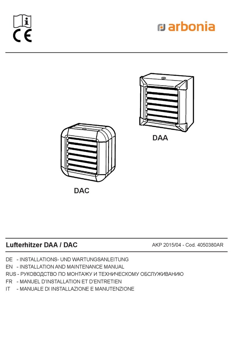
BGU WRAPTIME I/S User manual

USER’S MANUAL
Carefully read these instructions before starting
and using your fi rewood packer!
FIREWOOD PACKER
WRAPTIME I/S , II/S
Südharzer Maschinenbau GmbH
Helmestraße 94 ∙ 99734 Nordhausen/Harz
Zentrale: 03631/6297-0 ∙ 7-111
Internet: www.bgu-maschinen.de
e-mail: [email protected]
Set-up
Operation
Maintenance
Accessories

2
CONTENTS
1. INTRODUCTION 3
1.1 About the manual 3
1.2 Delivery and transport claims 3
1.3. Mandatory application field 4
2. SAFETY PICTOGRAMS AND WARNING LABELS 5
3. GENERAL SAFETY RULES 6
4. OPERATION 7
4.1 Description of the packing process 7
5. USE OF THE MOUNT FRAME 11
5.1 Installation of the mount frame 11
5.2 Installation of the hoist on the upper swing-arm 11
5.3 Setting the mount frame ready for operation 12
5.4 Connection of the electric chain-hoist 13
6. REPAIRS AND MAINTENANCE 14
6.1 Consumables 14
7. TechniCAL DatA 14
8. Transport 15
9. DIACTIVATING AND DISPOSAL 16
10. SPARE PART LIST 17
11. EC STATEMENT OF COMPLIANCE 23

3
1. INTRODUCTION
Dear customer, thank you very much for your trust and preference
choosing our equipment and joining the number of our best customers
in the world. We are confident that our equipment will be up to all your
expectations and ensure you a long lasting quality and performance.
Our firewood packing machine is available in the following two versions:
BGU Wraptime I/S - with electric rope hoist
BGU Wraptime I/S - with electric chain rope hoist
1.1 About the manual
Please take time to read this manual and learn to how operate and
maintain the equipment safely.
For your easier reading this manual is laid out in several sections. The
sections are progressively numbered 1 through 11 and listed on the
“contents” page.
The information, pictures and technical data in this document reflect current
or planned product features, functions, and characteristics as of the publi-
cation date. Because of on-going product improvements and feature additi-
ons, information in this document is subject to change without notice.
If you are experiencing a problem or functional trouble on your machi-
ne, please read the “trouble-shooting” section to identify possible cau-
ses and remedies. If the problem or functional trouble is not listed in
the troubleshooting chart contained in this manual ask your dealer or
our Authorized Service Centre for service.
When you order parts maintenance or repair services, your Authorized
Service Centre, your dealer or eventually the manufacturer will need
your machine serial number. These are the numbers that you have re-
corded on the product identification label of the manufacturer on the
machine
.
1.2 Delivery and transport claims
Upon delivery of the wood packer please check for visual machine da-
mages such as broken packing or scratched buckled parts. If so, make
a remark on all copies of the delivery bill before signing for accep-
tance.
Also have the truck driver sign al copies of the delivery bill.
Should your shipper or the truck driver refuse to accept your claim,
fully reject delivery of the machine and make sure to inform us (the
manufacturer).
.

4
No claims will be taken into account by the shipper or by the insurance
company, if a reservation note is not made on the delivery bill.
All transport damages must be notified within latest 2 days from deliv-
ery. Therefore delivery must be collected and inspected
within this term. Later claims will be disregarded.
In case of assumed but not visually clear transport damages make
sure to mark the following sentence on the delivery bill: „Reserved
delivery due to assumed transportation damages.“ Insurance
and shipping companies act with extreme caution in case of transport
damages and sometimes refuse to accept responsibility. Please make
sure to provide clear and exhaustive evidence (photos) of the claimed
damages.
Thank you in advance for your help and attention.
1.3. Mandatory application field
Wraptime is a piece of equipment designed to pack previously split
firewood in perfectly round packs with a diameter of 120 cm, 150 cm
high and with an approximate capacity of 1,7 cords.
Production-specimen approved to EC safety requirements (CE) All
packs are wrapped by a net and standing on a wooden pallet.
Packed pallets can be efficiently staked on each other, thus saving
enormous space. This machine is a must-have tool for neatly and ea-
sily packing your split logs so that they dry out faster without invading
your entire cellar space. No need for expensive containers. You can
move the pallets around by simply use any fork lift.
For best performance, we recommend to pack logs on:
• 120 x 120 cm wooden pallets or
• 120 x 80 cm Euro pallets
The latter can conveniently extended by simply nailing a 120 cm (47
in) plank across each short side of the pallet.
This machine should be strictly used for packing firewood logs. The
manufacturer will consider any other use or application as “misuse”,
in which case the manufacturer will not be responsible for customers’
claims or resulting damages.
Lack of compliance with these instructions may lead to dangerous risks
and situations and in which case the manufacturer will not be respon-
sible for customers’ claims or resulting damages and/or injuries.

5
1. BGU-Maschinen“ Manufacturer’s logo”
2. Identification label
This label shows the company details of the manufacturer and the
main technical data of machine.
3. Machine safety label „Read, understand, and
follow all instructions in this manual and on the
packer before starting!“
This safety label reminds the user about the importance of reading
and understanding the instructions of the manufacturer and getting
familiar with the machine before your first use it.
4. Machine safety label „Pinched hands danger“
Wear suitable protective gloves! Pinched hands danger in the wedge
hazard area. Keep your hands off all moving machine parts!
5. Machine safety label „Spooler“
Mind the correct activation and the direction of rotation of the spooler.
6. Operation safety label “DANGER! One-man ope-
ration only!
Possible dangers can arise from moving parts on the machine. The
machine is to be strictly operated by one man at a time only.
7. Safety-alert symbol
Very important: when you start the electric chain hoist, mind the di-
rection of rotation!
2. SAFETY PICTOGRAMS AND WARNING LABELS

6
Keep bystanders and unauthorized persons away from the
dangerous areas!
Do not alter the construction of the machine for no reason at all! Make
sure that the machine is properly and efficiently attached to the trac-
tor, and that the locking mechanism is perfectly and efficiently opera-
ting.
When transporting the machine, make sure to adjust the vehicle
speed depending on road conditions and the load, if available!! Do not
run the machine with worn-out, damaged, or missing parts.In this ca-
se, provide for immediate replacement making sure to strictly use ori-
ginal spares only!
The user shall strictly comply with these operation, set-up, mainte-
nance, repair and trouble-shooting instructions in order to assure safe
operation and avoid damages to the equipment. The owner must un-
derstand these instructions and must allow only persons who under-
stand these instructions and are familiar with the related risks to ope-
rate the splitter. Moreover, we recommend to let the machine be run
only and strictly by trained and skilled staff who must be familiar with
the applicable occupational safety and health administration rules as
well as applicable transportation rules.
No person under school leaving age (18) should operate this firewood
packer. Those who have reached school leaving age but are below the
age of 16 may operate a log splitter if supervised by a competent per-
son of 18 years or over.
The working area around the machine must be kept as clear as pos-
sible from surrounding obstacles. Make sure that the equipment
stands on a safe stable foundation.
Due and proper illumination of the working site must be provided at
all times.
Set up the machine on a firm surface which is free from stumps, boul-
ders, and obstructions and always wear snug-fitting, tear resistant
work clothes and shoes.
Make sure that all access ways are properly maintained so that wood
can be safely delivered, loaded and shipped.
3. GENERAL SAFETY RULES

7
Fig. 1
Fig. 2
Fig. 3
Fig. 1.1
Fig. 4
4. OPERATION
4.1 Description of the packing process
Settle the pallet under the collection barrel (Code no. 97173). Move
the barrel from the top down, onto the pallet.
Disengage the quick-fastener with rotary lock (Fig. 1.1)
The quick-fastening system allows rapid changing of the barrel when
you are working with more than one barrel at a time in a continuous
operation mode.
The quick-fastening system allows rapid changing of the barrel when
you are working with more than one barrel at a time in a continuous
operation mode.
Fill split logs into the barrel, to the rim. To check the wood level inside
the barrel use the special holes pierced in the barrel.
As soon as the barrel is full, close the top by performing the opening
sequence but in the opposite order. Secure it with the quick fastener.
Tie the net in a bottom corner of the wooden pallet, to start wrap-
ping and netting the wood. Pull the bracket with the spooler down to
a convenient position to swivel around the wooden pallet without ever
hitting against the corners. This operation requires special care if you
are working with larger pallets
120 x 120 cm
As soon as this is done and the barrel is full with wood, press the
push-button and start netting with the spooler.

8
BEWARE! Rotation must occur in the same direction as shown
by the arrow!
Make sure that the first two wraps are done below pallet top and firmly
around all corners (or alternatively underneath the extension planks).
This is to allow firm attachment of the net and avoid twisting or slip-
ping of the latter, which could cause later undoing of the wood pack. If
you are using 120 x 120 cm pallets, you may also cut off approxima-
tely 2/3 of the net, to obtain a net tail that you can easily and securely
pull around the pallet corners without tearing it.
Start wrapping, when the net is securely attached.
If you are using 120 x 120 cm pallets:Lift the barrel up, lock the fixati-
on screw on the spooler bracket, and make sure that any falling of the
spooler way down at pallet level is prevented.
If you are using 120 x 80 cm pallets: the spooler may also reach down
at floor ground.
To start packing, press the “wrap-around” button and the hoisting but-
ton to raise the barrel up while concurrently winding the net all around
the wood.
PLEASE NOTE: it is very important that both netting and barrel hoisting
are performed at the same speed in order to ensure that the finished
pack will be tightly and firmly held together. Failure to obtain sufficient
tightness of the pack may lead to further instability, or even undo the
pack.
Generally, operators keep continued pressure on the “wrap-around”
button, and discontinued pressure on the hoisting button, so that an
optimal speed rate is maintained.
.
Fig. 5
Fig. 6
Fig. 7

9
Should you note that the net is loose and does not hold together
tightly, pull the upper holder of the yellow spool bracket to adjust the
spooler tension.
When you do so, you will increase the slipping resistance, which
results into efficient netting.
Keep on wrapping and raising the barrel up until the latter is raised
and cleared nearly all the way up above the bunch of packed wood.
Now, stop hoisting the barrel and perform another 1-2 wraps
around the barrel. Cut the net and tie it up to the upper layers of the
wrapped net as tightly as you can. So the wood pack will be firmly
wrapped around and able to stand alone.
Fig. 8
Fig. 9
Fig. 10

10
Finally lift the barrel all the way up, so that you can remove the wood
pack and replace it with a new pallet.
Press the opposite push-button as the one used for hoisting and let
the barrel down to start a new cycle.
Wrapped wood packs ready for sale are safely and efficiently stackab-
le to save stocking place.
Fig. 11
Fig. 12
Fig. 13

11
5. USE OF THE MOUNT FRAME
Our Wraptime Packer can be used with or without a mount frame.
If you bought your Wraptime together with an optional*
• MOUNT FRAME (Mono) TR 150/1 (Code No. 97171) or
• Mount frame (Mono) TR 150/1 Euro-Kombi (Code No.97172)
Please make sure to read and comply with the following instructions.
If you did not buy the mount frame, you can always get one later and
use it with your machine.
The Mount Frame TR 150/1 (Mono) Euro-Kombi (Fig. 14) is recom-
mended for mobile applications on wood storage yards and fits any Eu-
ro-Combi carrier for attachment and transportation on a front loader or
rear tractor hydraulics!
5.1 Installation of the mount frame
Install the mount frame on a compact, smooth surface and secure it to
the floor stand with two M12 screws (Fig. 15).
5.2 Installation of the hoist on the upper swing-arm
If you bought our hoist version Wraptime I/S (Code no. 97165), with
electric rope, screw it directly to the plate that you find on the upper arm
of the mount frame. A bracket must be provided between plate and hoist
and attached to a power supply unit.
If you bought our hoist version Wraptime II/S (Code no. 97166) with
electric chain, make sure to bolt an adapter plate to the crane arm and
install a steel plate underneath it for attachment to the power distributor.
Strictly bolt the hoist to the adapter plate, when this is done.
*Accessories are not delivered by the manufacturer as part of the supply
scope. However, they can be ordered separately at any time.
*Zubehörteile sind keine Grundausstattung, auf Wunsch aber erhältlich und somit
zusätzliche Kosten
Fig. 15
Fig. 14
BEWARE! DO NOT FORGET TO PROVIDE GROUNDING OF BOTH
HOIST AND MOUNT FRAME!

12
5.3 Setting the mount frame ready for operation
The mount frame is delivered by the manufacturer completely folded
up for easier and cost-effective transportation.
a) Undo and remove all fixation bolts and pins
b) Use the manual winch to move the carrier construction to the re-
quired position (Keep lifting until the hole past the fixation pin can be
seen through the post)
c) Insert the fixation pin back into the hole and secure it with a cotter.
d) Release the winch rope to let the inner tube of the post
Do the other way around when you need to retract and fold the mount
frame. (see Fig. 18)
Fig. 17
Fig. 18
When you operate the „UP-button“, the chain will be completely woun-
ded up.
When you operate the „DOWN-button“, the chain will be completely
unwounded.
The rotation of the barrel must match the direction shown by the arrow
on the barrel. (see Fig. 16)
Fig. 16

13
5.4 Connection of the electric chain-hoist
Make sure to let the hoist be wired and connected to power by
a qualified electrician only.
The mount frame and the hoist are accessories that can be purchased
separately. For this reason they do not come with inbuilt earthing. As
they are both bound to receive a power voltage, efficient grounding
must be provided by customers. A green-yellow wire is available at the
power distributor. Connect it to the crane arm underneath the refe-
rence screw.
Ground the mount frame connecting an earth-wire to the screw provi-
ded on the rear side of the mount frame.
When connecting the winch to your power network, please check
the compliance of your supply with the specifications in this manual!
Should rotation be performed in the opposite direction, immediately
stop the machine and change the plugging polarity of the conductor
cable. The electric power socket must be fitted with a no-volt release
switch designed for rated current up to 30mA.
The manufacturer does not accept any liability for damages and inju-
ries resulting from failure to comply with these instructions
.
Clamping rope:
Tie the free end of the clamping rope
(the one pulled across the rear side of the mount-frame arm) to the
special eye bolt located underneath the floor-stand of the crane, and
secure it using a screw jack.
(see Fig. 19)
When working with a mount frame, make sure that the hook is secu-
rely attached to the Wraptime eye bolt through the cover lid.
(see Fig. 20)
Fig. 19
Fig. 20

14
6. REPAIRS AND MAINTENANCE
Always disconnect the machine from the power supply before
maintenance or repair works.
Before starting to work your machine, perform a functional and visual
check for eventual possible machine faults or damages.
Make sure to always use strictly original spare parts. This is very im-
portant for your own safety!!
Make sure to provide regular lubrication of all bearings.
6.1 Consumables
Bearing and springs are consumable parts that are not covered by any
warranty.
7. TECHNICAL DATA
Technical data Wraptime I/S Wraptime II/S
Electric chain hoist 1000 Kg
Electric rope hoist 400/800 kg
Gear motor (for rotati on) 0,29 kW P2 /0,38 kW P1 0,29 kW P2 /0,38 kW P1
Voltage
3 x 150 mm 400 V
Barrel capacity 1,7 cords 1,7 cords
Barrel height 1500 mm (0.49 in) 1500 mm (0.49 in)
Barrel Ø 1200 mm (0.39 in) 1200 mm (0.39 in)
Weight without carrier 210 kg (463 lb) 222 kg (489 lb)
The manufacturer reserves itself the right to change any of the fore going
data/specifications further to design/functional improvements or changes of
the machine
Technical data Tragerahmen TR 150/1 (Mono)
(Code no. 97171)
Tragerahmen TR 150/1
(Mono) Euro-Kombi
(Code no. 97172)
Height (when extended) 4250 mm (167 in) 4250 mm (167 in)
Height (when retracted) 2640 mm (104 in) 2640 mm (104 in)
Width 1500 mm (59 in) 1500 mm (59 in)
Length with barrel 1800 cm (71 in) 1800 cm (71 in)
Weight approx. 208 kg (458 lb) approx. 208 kg (458 lb)

15
8. TRANSPORT
The mount frame is delivered by the manufacturer completely folded
up for easier and cost-effective transportation.
The machine can be equipped with a Euro-Combi carrier (also see
Point 5) for attachment to a tractor:
• Front loader or
• Rear tractor hydraulics .

16
9. DIACTIVATING AND DISPOSAL
When the packer is fully obsolete and cannot be of any longer use,
it should be duly dismounted ahead of disposal. Certain components
need deactivation and dismantling in order to assure that no further
use is made by other parties and that no worn out parts are recycled
for other applications.
During dismantle be alert for possible recyclable materials and com-
ponents.
These materials may be possibly recycled if properly disposed of. The
manufacturer is not liable and undertakes no responsibility for perso-
nal injuries or damages that may result from the recycling of worn-out
machine parts and eventual re-use in other applications different than
originally stated in this manual.
Deactivation procedure:
Take good note please: each and every dismantling task must be per-
formed by authorized service centres or trained skilled staff only!
● Lock all moving parts of the mill and pull the machine down into sin-
gle components
● Deliver each single component only to authorized waste manage-
ment facilities
● Remove rubber and plastic parts from the machine that must be se-
parately disposed of.
Deactivated, clamped moving/driving parts and components are of no
further risk and danger.
Electric components must be separately disposed to avoid substantial
environmental threat. In the event of fire on the electric deployment
system of the machine, use of an explosion-proof extinguish system is
required (for example powder fire extinguishers).

17
10. SPARE PART LIST
Pos. Description (Wraptime) Dimensions
1 Motor lid
2 Gear motor
3 Motor plate
4 Motor mount
5 Screw M8x35
6 Screw M10x15
7 Self-locking nut M8
8 Screw M10x130
9 Self-locking nut M10
10 Screw M8x30
11 Nut M8
12 Belt 13780-001
13 Belt sheave, small
14 Screw M6x15
15 Sheave, large M6
16 Pin
17 Belt upper casing
18 Hex socket head cap screw M6x20
19 Belt sheave, large
20 Hex socket head cap screw M6x20
21 Belt bottom casing 1
22 Belt bottom casing 2
23 Hex socket head cap screw M4x8
24 Hinge M16
25 Greasing nipple M6
26 PRM Bushing 505540
27 Swivelling arm
28 PCMW flat washer 527802 B
29 Guide Arm
30 Screw

18
Pos. Description (Wraptime) Dimensions
31 Self-locking nut M16
32 Shim M16
33 Stud, locking bar
34 Screw with hex recess M6x20
35 Plastic pad 1
36 Hexagon socket head cap screw M6x15
37 Lever
38 Plastic pad 2
39 Hexagon socket head cap screw M6x10
40 Plastic pad 3
41 Hexagon socket head cap screw M6x10
42 Packing
43 Star screw M10
44 Stop
45 Screw M10x30
46 Hex socket head cap screw M5x5
47 Loader 1
48 Loader 2
49 Threaded rod M10
50 Nut M10
51 Bearing 6202
52 Bush 1
53 Bush 2
54 Grip
55 Tube
56 Barrel

19
Pos. Description (C R A N E) Dimensions
60 Hoist M16
61 Screw M10
62 Screw M5x6
63 Shim 5.5
64 Chain hoist, plate
65 Control panel for chain/rope winch
66 Spiral wire
67 Wire adjuster
68 Adjuster
69 Power cord
70 Plate for hoist control panel
71 Floor plate
72 Stand
73 Plastic pad 4
74 Hexagon socket head cap screw M6x10
75 Plastic pad 5
76 Hexagon socket head cap screw M6x10
77 Bolt
78 Split pin
79 Manual winch
80 Nut M8
81 Roller
82 Screw M10x50
83 Nut M10
84 Rope Ø 4mm,3500 lg
85 Rope Ø 4mm,3500 lg
86 Rope clamp M5
87 Rope clamp M6
88 Clamping vise

20
This manual suits for next models
1
Table of contents
Other BGU Industrial Equipment manuals
