Hoffmann 10585 User manual

Hoffmann GmbH Maschinenbau
2 User Manual
Intended Use .............................................................................................................................................................. 3
Safety instructions and safety devices ........................................................................................................................ 4
Technical data HOFFMANN Frame Joiner ................................................................................................................... 6
Noise level at the machine ......................................................................................................................................... 7
Warranty Statement................................................................................................................................................ 8
EC Declaration of Conformity ..................................................................................................................................... 9
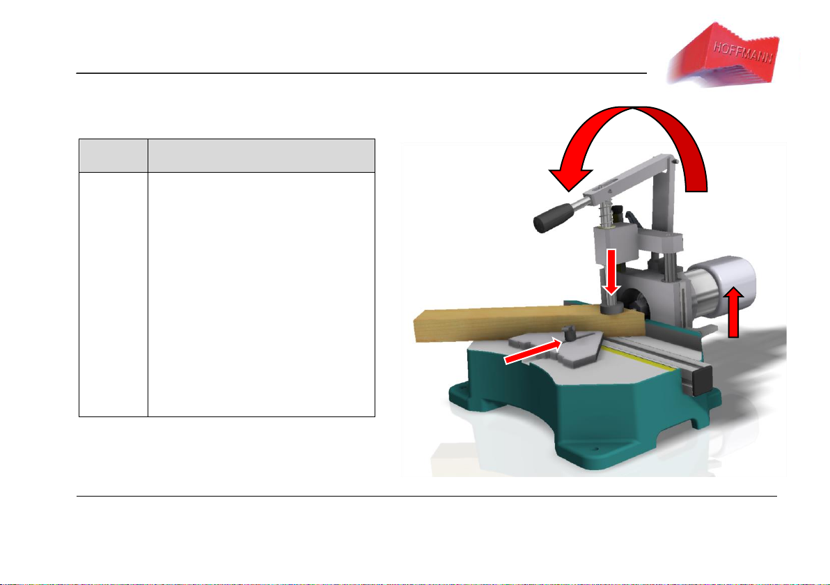
Function and operation of the machines ...................................................................................................................10
Scope of delivery, transport and storage ...................................................................................................................11
Cutter change and cutter adjustment........................................................................................................................15
Adjusting the routing groove length ..........................................................................................................................18
Malfunctions and troubleshooting ............................................................................................................................22
Machine plan Hoffmann Frame Joiner.......................................................................................................................23
Parts list Hoffmann Frame Joiner...............................................................................................................................24
Warranty and liability ...........................................................................................................................................25

Hoffmann GmbH Maschinenbau
User Manual 3
Intended Use
The HOFFMANN Frame Joiner routing machines are intended
exclusively for milling grooves in connection with the Hoffmann dovetail
connection system.
The use of the machines is only permitted for grooves of the Hoffmann
works standards W-0, W-1, W-2, W-3 and for wood or wood-like
materials, as well as MDF and multiplex.
Any other use of the Hoffmann Frame Joiner routing machines can
lead to hazards and is prohibited. The manufacturer is not liable for
damage caused by improper use. The user alone bears the risk for
this.
Technical changes to the system may only be made with the express
written approval of the manufacturer. All unauthorized modifications to
the machine exclude the manufacturer's liability for the resulting
damage.
The operator of the machine must make the operating manual
accessible to the people who operate and work with the machine. The
operator must ensure that these people are sufficiently trained and
have read and understood the operating instructions before working
with the machine.
Sign explanation
Mandatory sign.
It is imperative that the instructions
accompanying this sign are followed.
This symbol indicates a possible hazard
that can lead to serious, moderate or light
injuries or damage to property or the
machine itself.
This note contains no warning.
Here you will find application instructions
and other useful information.

Hoffmann GmbH Maschinenbau
4 User Manual
Safety instructions and safety devices
Danger: The following safety instructions
must be observed!
Read these operating instructions carefully and keep them safe. Observe all instructions
and safety information, as well as all applicable safety and occupational health
standards, guidelines and laws when handling electrical products.
1. The HOFFMANN Frame Jointing machines may only be operated after the operating personnel have read and understood the
operating instructions. The manual should be kept ready to hand as a reference work.
2. Only persons who are authorized to do this and who are familiar with the handling may work on the HOFFMANN Frame Jointing
machines ! Keep all persons not working on the milling machine away! The operating personnel must switch off the machine
electrically as long as the machine is not being supervised or is not being worked on.
3. Work on the electrical equipment may only be carried out by a qualified electrician!
4. Before connecting the Frame Joiner routing machine electrically, the connection values must be checked using the "Technical
Data"!
5. Safety devices must not be disabled!
6. The Frame Joiner routing machine may only be switched on if there is no danger to persons or property!
7. The function and condition of the safety devices must be checked quarterly!

Hoffmann GmbH Maschinenbau
User Manual 5
8. If damage or errors are found on the Frame Joiner routing machine that could endanger persons or property, the Frame Joiner
machine must be shut down immediately and further use prevented until it has been completely repaired! The operating personnel
must report any faults on the machine and its protective devices immediately after they have been noticed.
9. If the Frame Joiner routing machine is shut down for a longer period of time, the safety devices must be checked and, if necessary,
repaired before it is put back into operation.
10. Always wear close-fitting work clothing and a hair guard (if you have long hair) to prevent clothing or hair from getting caught in the
machine. Wear protective goggles for every work step and wear hearing and respiratory protection when working for longer
periods.
11. Ensure there is sufficient lighting at the workplace with a room temperature of approx. 20°. It is important to ensure that the floor
around the machine is free of waste, chips and leftovers.
12. Do not reach into the area of the cutting tools. Protective gloves are recommended when working in the area of the milling tools
and when handling milling tools! The milling tools must be checked daily for sharpness and breakage.
13. Do not allow the machine to come into contact with moisture, water, or flammable liquids or gases.
14. Lay out the power-carrying lines so that nobody can trip over them and the lines can be damaged
15. Disconnect the machine from the electrical power supply during maintenance and repair work.

Hoffmann GmbH Maschinenbau
6 User Manual
Technical data HOFFMANN Frame Joiner
Frame Joiner
Speed control
Number of engines
1
1 = 13.000 rpm
Direction of rotation
to the right
2 = 17.000 rpm
Speed (milling spindle) adjustable
10.000-30.000 rpm
3 = 22.000 rpm
Tool holder, collet
Ø6 mm
4 = 29.000 rpm
Milling height (max)
55 mm
5 = 31.000 rpm
Dovetail size
W - 1 / 2 / 3
6 = 33.000 rpm
workpiece height (max)
75 mm
Table height
80 mm
Optimum speed for:
Dimensions (W x D x H)
370 x 400 x 400 mm
Cutter: W0 / W1 / W2 / W3
Weight
7,0 kg
level 3 = 22.000 rpm
Engine power
710 Watt
Electrical connection values
230 V 50/60 Hz
Connection values pneumatic
--
milling feed
Manually
workpiece clamping
Manually
Extraction nozzle - diameter
38mm
Emission values (noise)
88,43 dB(A)

Hoffmann GmbH Maschinenbau
User Manual 7
Noise level at the machine
The continuous sound pressure level emanating from the machine is approx. 88.43 dB(A). Depending on
local conditions, a higher sound pressure level can result, causing hearing damage.
In this case, the operating personnel must be protected with appropriate protective equipment or
protective measures.
Notes on the noise specification
The specified values are emission values and therefore do not have to represent safe workplace values at the
same time.
Although there is a correlation between emission and emission levels, it cannot be reliably deduced from this
whether additional precautionary measures are necessary or not.
Factors that influence the current emission level at the workplace include the nature of the workspace, other
sources of noise, e.g. the number of machines and other neigh boring work processes. The permissible workplace
values can also vary from country to country. However, this information should enable users to make a better
assessment of the hazard and risk.

Hoffmann GmbH Maschinenbau
8 User Manual
Warranty Statement
Our general terms and conditions (VDMA) apply to warranty services.
Warranty period
The guarantee period is 12 months from the date of delivery. It extends to the free elimination of all
faults that arise as a result of poor workmanship or material defects. A warranty repair does not extend
the warranty period for either the replaced parts or the device.
Warranty
processing
Warranty services are provided ex works in Bruchsal or by the supplier. Accessories and spare parts
are specially designed for the keyway routing machines.
Exceptions and Loss
of Warranty
Excluded from the guarantee are damages or malfunctions that are due to improper use, incorrect
setup or installation, external influences (e.g., damage in transit, damage caused by shock or impact),
repairs and modifications made by third parties, unauthorized bodies and damages that are due to are
due to natural wear and tear.
We would like to point out that machine parts and accessories not supplied by us have neither been
checked nor approved by us. The installation and use of such products may adversely affect the design
properties of the device. This will affect safety and functionality.
The manufacturer accepts no liability whatsoever for damage caused using "non-original parts" and
accessories.

Hoffmann GmbH Maschinenbau
User Manual 9
EC Declaration of Conformity
in terms of EU Directive 2006/42/EC
We hereby declare,
Hoffmann GmbH Maschinenbau
Mergelgrube 5 76646 Bruchsal
Deutschland
that the machine
Machine designation
Machine type
Machine number
Hoffmann Frame Joiner 10585
Keyway routing machine
__________________
The version supplied complies with the following relevant provisions:
2014/35/EU u. 2014/30/EU EMC and Low Voltage Directive
93/68/EWG:1993-07-22
EC low-voltage directive and EC EMC directive
Applied harmonized standards, in particular:
DIN EN 61029-1+A11:2010-02-28
DIN EN 61029-2-8:2010-09
EN 61000-3-2:2014
EN 61000-3-3:2013
EN 55014-1:2017
EN 55014-2:2015
Place & Date of production
Bruchsal, .2023
Signature
Thomas Hoffmann
Head of Technology

Hoffmann GmbH Maschinenbau
10 User Manual
Function and operation of the machines
Type
Function and working method
Frame
Joiner
Manual table routing machine
The milling position on the workpiece is
determined by moving the stop elements
and the desired milled groove length is
pre-set using the measuring pin.
The workpiece is clamped by pulling the
hand lever of the machine.
If the hand lever is pulled further down
from this position, the milling unit moves
up.
After the milling unit has reached its end
position on the measuring bolt stop, the
hand lever is returned to its starting
position and the milling process is
complete.

Hoffmann GmbH Maschinenbau
User Manual 11
Scope of delivery, transport and storage
Scope of delivery:
The HOFFMANN Frame Joiner machines consist of:
•HOFFMANN Frame Joiner machine, ready for connection, ready for
operation
•Tool kit, consisting of: Size 22 open-end wrench and a 4mm Allen key.
•Operation manual
Transport:
The machine is delivered in a stable, transport-safe plastic box. Check whether the content of
the shipment matches the information on the delivery note. In the event of transport damage,
please inform the transport company immediately so that the damage can be determined, as
well as the Hoffmann company or your dealer.
Attention:
The machine may fall or tip over.
When transporting, be sure to wear protective gloves and safety shoes with
steel toes.
Storage:
The machine should remain in its packaging for storage. The storage room itself must be dry to
prevent individual parts from corroding. Optimal storage is at a room temperature of 18-25°C.

Hoffmann GmbH Maschinenbau
12 User Manual
Commissioning and maintenance
Setting up the machine
Remove the transport packaging and clean the machine with a suitable machine cleaning agent
(e.g. WD40).
The machine is set up on a sufficiently stable table. The table plane must be sufficiently large,
evenly flat and level so that the machine is stable.
Electrical connection
Before commissioning, check whether the mains voltage corresponds to the information on the
machine type plate and the type of plate of the milling motor. If all information is correct, connect
the machine plug directly to the socket.
Extraction system connection
The machine type MU-S has an extraction connection on the rear side of the machine.
When working with the machine for a long time, the suction must be connected. The suction
channel leads directly under the milling unit. This means that the suction has a high efficiency,
and the chips are sucked up directly below the milling cutter.
The minimum air speed required for extraction at the extraction nozzle of the machines is 20
m/s for dry chips and 28 m/s for moist chips (humidity >18%).
To do this, an extraction system must be connected that at least achieves the following values:
1.) Minimum flow rate at the intake manifold = 250m³/h
2.) Minimum vacuum at the intake manifold = 14000 Pa

Hoffmann GmbH Maschinenbau
User Manual 13
Maintenance and care of the machine
Attention:
Always pull out the mains plug for all maintenance and care
work.
Maintenance
interval
Module
Action
Daily
Tool and chip breaker
Router motor
Checking the tool and the chip breaker for wear, damage and
cracks. Replace if necessary.
Check the ventilation slot of the milling motor for dirt and
clean if necessary.
Weekly
Machine housing
Guides and bearings
Clean the complete machine with a suitable machine cleaning
agent (e.g., WD40)
Grease the linear unit with machine grease
(e.g., ESSO Grease LT2)
Repair work may only be carried out by the manufacturer or authorized persons.

Hoffmann GmbH Maschinenbau
14 User Manual
The Hoffmann Frame Joiner system
Due to the extremely precise double wedge shape of the Hoffmann-dovetail, the parts to be connected are pressed together exactly and
permanently due to the forced guidance.
The milling cutter setting dimension must be adhered to exactly for optimal matching.
The correct setting dimension "X" for the
Type W1 be 3,5 mm.
Type W2 be 5,1 mm.
Type W3 be 6,9 mm.
With this setting, the Hoffmann dovetail connector optimally pulls the frame parts together.
The machine is preset at the factory to the customer's router and ensures appropriate
pressure for the types of wood: hardwood and softwood, MDF, chipboard and multiplex.
Incorrect:
If the adjustment is less than the minimum adjustment, no
pressure is generated on the joint surface and a gap is
formed.
That is, the two frame parts are not fully assembled.
Incorrect: Milling depth too great.

Hoffmann GmbH Maschinenbau
User Manual 15
Cutter change and cutter adjustment
Attention:
Always pull out the mains plug for all adjustment work on
the milling motor.
The milling tool has very sharp cutting edges. Protect
your hands!
Removing the milling motor from the motor mount
Place the milling unit above the table level and fix this
position by clamping the height slider (2) with the
clamping lever (1).
Open the clamping screw (3) of the motor mount
The milling motor can now be moved back and forth in
the holder.
Remove the motor from the mount or use the setting
gauge to set the routing depth of the cutter →See the
following chapter.
1
2
3

Hoffmann GmbH Maschinenbau
16 User Manual
Adjust cutters and change chip breakers
The cutter setting gauge is part of the 90° stop plate.
To use the gauge, the stop plate must be removed from the machine table and turned over so that it can be placed
directly on the stop edge.
Loosen the motor in the mount as previously described.
The milling motor can now rotate forwards and backwards
in the holder be moved back until the cutter tip is flush with
the reference surface of the setting gauge.
Clamp the milling motor back into the motor mount by
hand-tightening the clamping screw
Put a new chip breaker in the machine.
Switch off the motor at the motor housing and plug the
mains plug into the socket.
Mill through the chip breaker from top to bottom by
manually slowly returning the milling motor to its home
position.
Attention: Free-running milling spindle.
Be sure to protect your eyes safety goggles and wear
protective gloves.

Hoffmann GmbH Maschinenbau
User Manual 17
Handling of milling cutter and collet
Open the cutter collet by turning the union nut (1) with an
SW22 open-end wrench. The gear shaft is secured against
twisting with the locking knob.
Insert a cutter or replace the old cutter with a new one.
If necessary, clean the collet or check whether the collet is
firmly anchored in the spring washer of the union.
With the help of a commercially available calliper, the required
setting dimension of the milling cutter type used is now set.
Close the collet by turning the union nut while holding the gear
shaft with the locking button.
Test the newly adjusted milling depth by making two test
pieces and joining them with a Hoffmann dovetail connector.
If the test pieces are connected properly, the adjustment is
complete. Otherwise, repeat the steps again.
Cutter type
Setting Dimension
W1
20,0 mm
W2
22,0 mm
W3
24,0 mm

Hoffmann GmbH Maschinenbau
18 User Manual
Adjusting the routing groove length
The milling groove length of the machine is limited by setting the measuring bolt.
By setting the measuring pin depending on the corresponding workpiece thickness, a
faster work cycle is possible and accidental "milling through" of the workpiece is
prevented.
Groove length adjustment
Open the clamping lever (1) and set the measuring pin to the
desired milled groove length. The set slot length can be read
directly on the ring surface (2) of the motor bracket. Close the
lower clamp lever to fix the setting.
2
1

Hoffmann GmbH Maschinenbau
User Manual 19
Depiction: machining operation
with the 45° stop plate.
Working with the Hoffmann stop system.
Thanks to the special stop system of the Hoffmann machines, the workpieces
can be precisely milled in different variants. Here, workpieces with different
angles as well as workpieces with radii can be processed without any problems.
The Frame Jointing machines are equipped with a 45° stop plate (1) and a 90°
butt stop (2). By moving the stops, different milling positions can be set on the
workpiece. With the 45° stop plate it is possible "right" and "left" 45° cut
workpieces in a single stop setting to edit. The workpiece dimensions are limited
by the workpiece width, which may not exceed 75mm.
All workpieces that are wider than 75mm or have a different angle or have a
radius are machined with the 90° butt stop. To do this, the 45° stop plate is
loosened and removed from the machine table.
For "right" / "left" processing, the 90° butt stop is positioned alternately on the
right or left side of the machine. The position of the stop at the 90° butt stop
edges is read directly on the measuring tape scales on the machine table. The
milling position(s) on the workpiece depend on the profile and are freely defined
by the operator.

Hoffmann GmbH Maschinenbau
20 User Manual
Profile shape / cut
Machining workpiece 1
Machining workpiece 2
Connection of
workpieces with any
angle .
Connection of radii
and arcs with any
angle.
Table of contents
Other Hoffmann Industrial Equipment manuals

Hoffmann
Hoffmann eXess User manual

Hoffmann
Hoffmann GARANT HiPo Clamp 125 User manual

Hoffmann
Hoffmann MU2 User manual

Hoffmann
Hoffmann X-10 User manual

Hoffmann
Hoffmann MORSO NM User manual

Hoffmann
Hoffmann Garant User manual

Hoffmann
Hoffmann MORSO NFXL User manual

Hoffmann
Hoffmann GARANT VG Basic User manual

Hoffmann
Hoffmann FX Series User manual