ECS PAV-D User manual

Specifications
Stock Number:
Service Pressure:
System Connection:
Temperature Range:
Dimensions:
Weight:
For use under U.S. Patents
8,720,591, 9,144,700, 9,186,533
and 9,610,466
PAV-D
Up to 175 PSIG (12 Bar)
1” NPT Male
40°F - 120°F (4.5°C - 49°C)
13.5” (W) x 7.5” (H) x 4.25” (D)
343mm (W) x 191mm (H) x 108mm (D)
7 Lbs. (3.1 Kg)
General Description
The ECS Protector Manual Vent provides oxygen venting in dry pipe fire sprinkler systems. As a fire sprinkler
system is filled with a continuous supply of nitrogen gas from the ECS Protector Nitrogen Generator System,
the ECS Protector Manual Vent allows oxygen rich gas to be vented from the fire sprinkler system. Over a
short period of time the ECS Protector Manual Vent will almost completely remove oxygen from the fire
sprinkler system (<2% oxygen).
The ECS Protector Manual Vent must be installed as shown on the engineering design documents. If a
location is not specified install the ECS Protector Manual Vent on the fire sprinkler system riser on the system
side of the main control valve. The vent is also installed to provide source gas when used in conjunction with
the ECS Protector SMART Gas Analyzer (SGA-1).
The ECS Protector Manual Vent is equipped with a levered float valve that allows oxygen to discharge but
prevents liquid water from leaking through the restricted venting orifice in the event that water enters the fire
sprinkler system. A backpressure regulator is also included to prevent total system depressurization from the
vent assembly.
The restricted venting orifice allows oxygen to be vented from the fire sprinkler system at a controlled rate to
achieve a minimum nitrogen concentration of 98%. A special fitting is provided to receive 5/32” tubing when
the vent is used in conjunction with the ECS Protector Permanent Gas Analyzer.
April 2020 - Rev 21
ECS PROTECTOR
MANUAL VENT
PAV-D
Engineered Corrosion Solutions •11336 Lackland Road St. Louis, MO 63146 •Phone: 314.432.1377 •www.ecscorrosion.com
There are two models of the ECS Protector Oxygen Removal Vent,
the PAV-D and the PSV-D (PSV-DE) The units both operate as
described above but the PSV-D (PSV-DE) model includes an
electronic solenoid valve wired to a control panel that automatically
closes the vent once the desired nitrogen concentration has been
reached. The control panel is also equipped with an on/off switch
and vent button to provide a means to allow the venting process to
restart should oxygen be reintroduced into the fire sprinkler system.

Installation Instructions
Operating Instructions
1. The ECS Protector Manual Vent is equipped with a ball valve to be connected to the fire sprinkler riser. The
contractor must install a 1” outlet (welded or mechanical) to connect the vent assembly to the sprinkler system
on the system side of the main control valve (see Figure 2). The ball valve must remain in the closed position
until the ECS Protector Nitrogen Generator System has been commissioned.
2. Install the vent assembly in a level position. Recommended mounting height is between 5’-10’ (2-3m) above the
finished floor.
NOTE: Piping to the vent assembly cannot be installed in a configuration that would trap water and prevent
drainage to the sprinkler system; a water trap impedes the ability of the vent assembly to vent oxygen
from the fire sprinkler system.
3. Inspection of the vent assembly should be performed after installation and hydrostatic testing of the fire
sprinkler system. Inspection should be performed periodically thereafter in accordance with the applicable
national codes, NFPA codes and standards and/or the authority having jurisdiction.
NOTE: Inspection must include the condition of the in-line filter and checking for blockage in the “Y” strainer
and the restricted venting orifice.
1. Verify the vent assembly has been equipped with a restricted venting orifice downstream of the backpressure
regulator.
NOTE: If the vent assembly is not equipped with a restricted venting orifice, one will be provided by ECS during
system commissioning. The restricted venting orifice must be installed before proceeding with the steps
below.
2. Determine the low air alarm pressure and the turn-on pressure of the nitrogen generator.
3. Choose a pressure setting for the backpressure regulator that is above the low air alarm pressure but below the
turn-on pressure of the nitrogen generator.
4. Pull the knob out from the regulator to adjust pressure setting. Turn the knob clockwise to raise the pressure,
counter-clockwise to lower the pressure.
5. Close the ball valve and allow device to depressurize through restricted venting orifice to pressure setting. Make
adjustment to pressure setting using the knob, then open ball valve to pressurize device and close ball valve
again to check pressure setting. Repeat process until desired pressure setting is achieved.
NOTE: This process can only be performed when fire sprinkler system is at normal operating pressure.
6. Push knob back into regulator until it clicks into place.
7. Once the ECS Protector Nitrogen Generator System has been commissioned, open the isolation ball valve on
the vent assembly. The ECS Protector Manual Vent is now open and actively venting oxygen from the fire
sprinkler system. It should remain open for approximately 14 days or until the system nitrogen concentration
reaches 98% or greater. Use an ECS Protector Handheld Gas Analyzer to verify the gas concentration inside
the fire sprinkler system.
8. Close the isolation ball valve. Failure to close the manual ball valve after 14 days or once fire sprinkler system
nitrogen concentration reaches 98% will result in additional oxygen corrosion damage to the system and
unnecessary run time of the air compressor and nitrogen generator.
9. If the sprinkler system actuates or another event introduces oxygen to the sprinkler system the manual ball valve
must be opened again for a period of 14 days to vent oxygen from the system.
April 2020 - Rev 22
ECS PROTECTOR
MANUAL VENT
PAV-D
Engineered Corrosion Solutions •11336 Lackland Road St. Louis, MO 63146 •Phone: 314.432.1377 •www.ecscorrosion.com

FIGURE 1 - In-Line Filter
April 2020 - Rev 23
ECS PROTECTOR
MANUAL VENT
PAV-D
Engineered Corrosion Solutions •11336 Lackland Road St. Louis, MO 63146 •Phone: 314.432.1377 •www.ecscorrosion.com
Pressure Relief Valve
Filter Housing
Filter
In-Line Filter Replacement Instructions
1. Close the isolation ball valve.
2. Depressurize the housing by pressing the pressure relief valve on the bottom of the in-line filter housing.
3. Remove the lower section of the in-line filter housing by turning the filter housing counterclockwise.
NOTE: A rubber o-ring/seal is located between the upper and lower sections of the filter housing.
4. Remove the old filter by turning the filter counterclockwise.
5. Replace with new filter (PV-DRF-Black Housing, PV-DRF2-Clear Housing). The filter is secured to the housing
by turning the filter clockwise.
NOTE: Ensure the filter is secured only finger/hand tight.
6. Install the rubber o-ring/seal on the lower section of the filter housing.
7. Re-install the filter housing by turning the filter housing clockwise.
NOTE: Ensure the filter housing is secured only finger/hand tight.
8. Open the isolation ball valve.
Maintenance Instructions
1. The ECS Protector Manual Vent must be inspected annually at minimum. While the isolation ball valve is in the
open position check for air/water leaks and ensure the pressure gauge is displaying normal system pressure.
2. While isolation ball valve is in closed position inspection must include the condition of the inline filter and for
blockage in the “Y” strainer and restricted venting orifice. Twist the filter housing clockwise until it can be removed
to expose the filter element.
3. The filter element in the in-line filter should be replaced if a visual inspection reveals a significant collection of
debris.
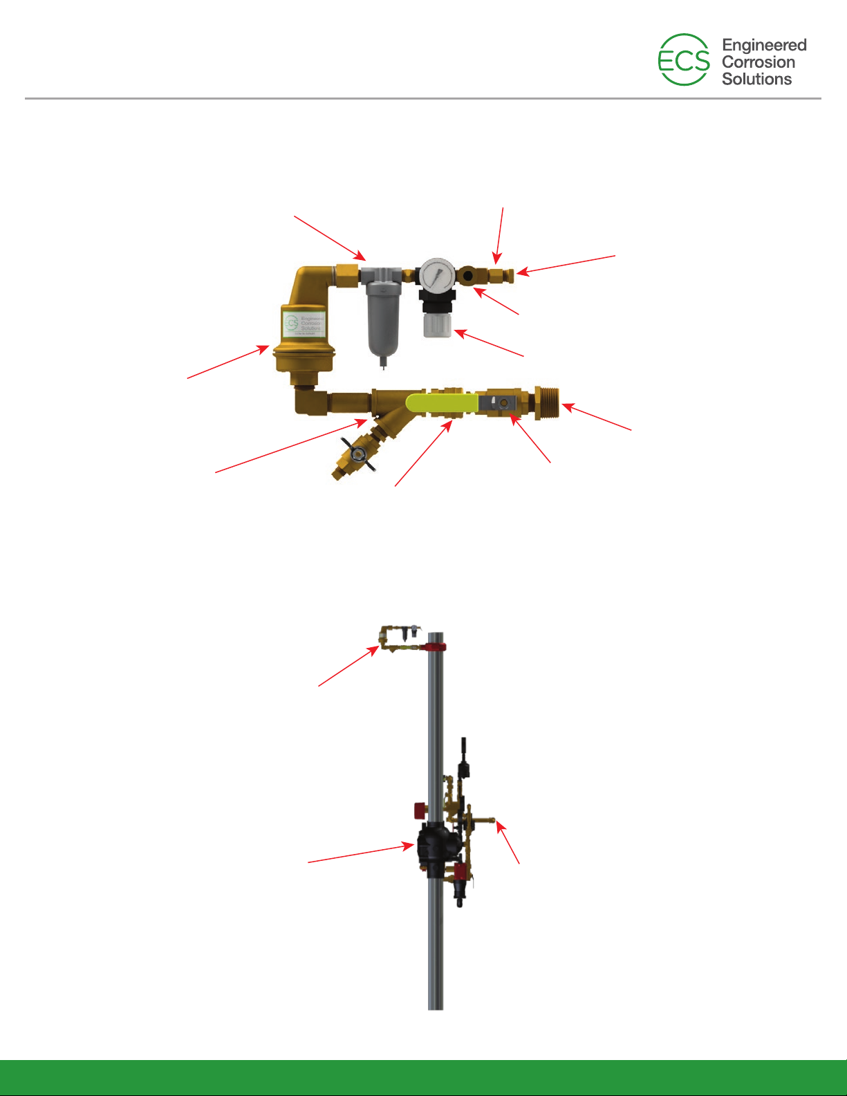
FIGURE 2 - ECS Protector Manual Vent Components
FIGURE 3 - ECS Protector Manual Vent Installation Schematic
“Y” Strainer
with Ball Valve
Quick Connect
Backpressure Regulator
Isolation Ball Valve
Restricted Venting Orifice
Gas Sample Port
Connection to
Sprinkler System
Muffler
In-Line Filter
Float Valve
April 2020 - Rev 24
ECS PROTECTOR
MANUAL VENT
PAV-D
Engineered Corrosion Solutions •11336 Lackland Road St. Louis, MO 63146 •Phone: 314.432.1377 •www.ecscorrosion.com
Fire Sprinkler Riser
Vent
Assembly
Nitrogen Supply
Table of contents
Popular Industrial Equipment manuals by other brands


LNS
LNS TRYTON 112 instruction manual

Parker
Parker SciLog FilterTec Plus Installation, operation & maintenance instructions

LumaSense technologies
LumaSense technologies 1303 user manual

R.V.R. Elettronica
R.V.R. Elettronica HC5-10 user manual

Wacker Neuson
Wacker Neuson RD 7 Series Operator's manual

Pepperl+Fuchs
Pepperl+Fuchs ECHO-D Brief instructions


