manuals.online logo
Brands
  1. Home
  2. •
  3. Brands
  4. •
  5. Miranda
  6. •
  7. Amplifier
  8. •
  9. Miranda DENSITE series Instruction Manual

Miranda DENSITE series Instruction Manual

SÉRIE DENSITÉ
ADA-1001 -Analogue Audio Distribution Amplifier
Guide to Installation and Operation
M450-9900-100
janvier 2002
ADA-1001
Introduction
L’ADA-1001 enables distribution of one analogue signal (audio
or time code) to four outputs.
All modules of the DENSITE Series include a push button on
the card front edge, which can assign the front panel controller
to consultation and adjustments of the board parameters. A
multi-coloured Led, visible with the door closed, reports the
card status.
The module gain is trim controlled (–8 to +32 dB) from the card
edge and set with a jumper.
The ADA-1001 requires a ‘single’ rear connector panel.
Features
•Analogue audio Distribution Amplifier 1 input / 4
outputs
•Balanced input and outputs
•Gain trim adjustment on card (-8 to +32 dB)
•Status LED and remote reporting
•Alarm configuration: absence signal, overload
•Easy to install audio connectors
AUDIO
OUTPUTS
AUDIO
INPUT
ADA-1001 Functional Block Diagram
Microcontroller
1
2
3
4
Rem
Control
Select
Status
Amp
Specifications
Input
Balanced
Signal: ......................analogue audio
Impedance: ..............> 20 k Ω
Common mode
rejection: ..................> 50 dB
Output
Balanced
Signal: .....................balanced analogue audio
Impedance: ..............< 50 Ω
Processing performance:
Gain: ........................-8 to +32 dB
Max. Level:................+25 dBu
SNR: ........................< -95 dBu
..................................20 Hz to 20 kHz unweighted
Distortion: .................< -85 dB (20 Hz to 20 kHz) @ +23 dBu
Freq. response: ........±0.2 dB (20 Hz to 20 kHz)
Overload threshold: .+23 dBu
Signal absence
-threshold:................-36 dBu
-no signal delay:.......from 0 to 255 s
Miscellaneous
Power:.......................3.5 W
Specifications are subject to change without notice.
ADA-1001
Guide to Installation and Operation
Menu Introduction
Most parameters are accessed and changed via an easy-to-use menu. The flow chart below outlines the entire ADA-1001
menu path. Each menu is described throughout this section.
The procedure and the operation mode are described in the common paragraph of the DENSITÉmanual. The menu
organisation is made out of a main menu and several sub-menus. A press on the [SELECT] front panel push button accesses
the menu. A lack of activity turns off the display. Default values are written with bold characters.
NO SIGNAL DELAY
CONFIGURE ALARM
STATUS
FACTORY DEFAULT
OVERLOAD ALARM LEVEL
ALARM REPORT
NO SIGNAL
ALARM REPORT
ALARM LEVEL
NONE, GPI
NONE, GPI
GREEN, YELLOW, RED, FLASH RED
0, ..., 15, ..., 255 [sec]
REAR PANEL ERROR, OVERLOAD, NO SIGNAL, ALL OK
RESTORE
Menu Description
{STATUS}
Displays status of the different board alarms. The higher-level
alarm is displayed, even if not configured to activate the
STATUS led. ALL OK indicates an absence of alarm.
REAR PANEL ERROR Indicates an absence of the rear
panel or an incompatibility between
the module and the rear panel. The
STATUS led turns on flashing red.
OVERLOAD Indicates an internal signal level
higher than +23 dBu.
NO SIGNAL Indicates an internal signal level lower
than –36 dBu during a user defined
period.
{NO SIGNAL DELAY}
NO SIGNAL DELAY Signal absence is declared when the
level signal is lower than –36 dBu
during the selected period, it can be
adjusted from 0 to 255 s. The default
value is set to 15 s.
ADA-1001
Guide to Installation and Operation
{CONFIGURE ALARM}
It is possible to associate the STATUS Led colour and/or a
GPI relay activation to each detected error.
Alarm relay activation depends of the ENABLE selection of
the controller board menu GPI REPORT.
ALARM LEVEL Associates to each error the STATUS
led colour: GREEN, YELLOW, RED
and FLASH RED. This selection has
no influence on the {STATUS} menu
display.
ALARM REPORT The default value NONE is assigned
to errors. Alarm relay activation will
be associated to an error when GPI is
set.
{FACTORY DEFAUT}
RESTORE reset the module with the factory default
parameters.
Status and Report
This table shows the STATUS led colour and the report action according to the level of a given error condition. Notice that the
“Flashing Yellow” indicates that the SELECT button on the front panel has been pushed, and the card is being accessed via the
communication protocol.
Non requested
messages GPI
Report Green Yellow Red Flashing
Red Flashing
Yellow
Overload on Input 1 µµ µµ -
No signal detected on Input 1 µµ µµ -
Card accessed via the communication protocol Yes
Rear Panel not matching -----Yes -
Factory default. µµ
Note: The non requested message affectation to an alarm status can only be accessed by the communication protocol (serial
port)
ADA-1001
Guide to Installation and Operation
Front Edge Presentation Board Presentation
PT1
1
ADJ.
STATUS
D1
SELECT
SW1
Push Button
Status Indicator
Gain Adjustment
ADA-1001
Configuration
PT1
1 GAIN GAIN ADJUSTMENT
Trimmer for fine adjustment of the gain with an 8 dB
range.
JP1 The adjustment range is determined by the JP1
position.
-8 to 0, 0 to 8, 8 to 16, 16 to 24, 24 to 32,
Connections
ADA-1001 is used with the single rear panel ADA-1001-SRP
that includes 1 input to 4 outputs.
ADA-1001
1
2
3
4
AUDIO OUT
AUDIO
IN
ADA-1001-SRP
3
2
1
High
GND
Low
JP1

Other manuals for DENSITE series

12

This manual suits for next models

1

Other Miranda Amplifier manuals

Miranda DENSITE series Instruction Manual

Miranda

Miranda DENSITE series Instruction Manual

Miranda Densite HDA-1861 Instruction Manual

Miranda

Miranda Densite HDA-1861 Instruction Manual

Miranda ADA-702i Instruction Manual

Miranda

Miranda ADA-702i Instruction Manual

Miranda HDA-1811 Instruction Manual

Miranda

Miranda HDA-1811 Instruction Manual

Miranda Densite series DDA-1113 Instruction Manual

Miranda

Miranda Densite series DDA-1113 Instruction Manual

Miranda SDA-122 Instruction Manual

Miranda

Miranda SDA-122 Instruction Manual

Miranda imaging Series Instruction Manual

Miranda

Miranda imaging Series Instruction Manual

Miranda DDA-1112 Instruction Manual

Miranda

Miranda DDA-1112 Instruction Manual
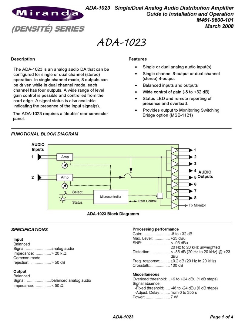
Miranda ADA-1023 Instruction Manual

Miranda

Miranda ADA-1023 Instruction Manual

Miranda SDA-172p User manual

Miranda

Miranda SDA-172p User manual

Miranda DENSITE HDA-1851 Instruction Manual

Miranda

Miranda DENSITE HDA-1851 Instruction Manual

Miranda VEA-1002 Instruction Manual

Miranda

Miranda VEA-1002 Instruction Manual

Miranda DENSITE series Instruction Manual

Miranda

Miranda DENSITE series Instruction Manual

Miranda VDA-1001 Specification sheet

Miranda

Miranda VDA-1001 Specification sheet

Miranda HDA-1832 Instruction Manual

Miranda

Miranda HDA-1832 Instruction Manual
Miranda HDA-1801 Instruction Manual

Miranda

Miranda HDA-1801 Instruction Manual

Miranda DENSITE series Instruction Manual

Miranda

Miranda DENSITE series Instruction Manual
Miranda DENSITE series Instruction Manual

Miranda

Miranda DENSITE series Instruction Manual

Popular Amplifier manuals by other brands

Pyle PLMRA210BT user manual

Pyle

Pyle PLMRA210BT user manual

Creative Sound Blaster E3 SB1610 user guide

Creative

Creative Sound Blaster E3 SB1610 user guide

M-Audio DMP2 manual&nbsp;

M-Audio

M-Audio DMP2 manual&nbsp;

YBA DESIGN P1000 Service manual

YBA DESIGN

YBA DESIGN P1000 Service manual

Crown PL-2 instruction manual

Crown

Crown PL-2 instruction manual

Marantz PM6002 Service manual

Marantz

Marantz PM6002 Service manual

Beyerdynamic A 20 user manual

Beyerdynamic

Beyerdynamic A 20 user manual

Pioneer A-8 operating instructions

Pioneer

Pioneer A-8 operating instructions

PBN EDFA-R Product user manual

PBN

PBN EDFA-R Product user manual

RM KL 35 Schematic diagram

RM

RM KL 35 Schematic diagram

Harman Kardon HK6100 Technical manual

Harman Kardon

Harman Kardon HK6100 Technical manual

Behringer BASS V-AMP LX1B user manual

Behringer

Behringer BASS V-AMP LX1B user manual

AUSTRALIAN MONITOR AMH3600 Installation and operation manual

AUSTRALIAN MONITOR

AUSTRALIAN MONITOR AMH3600 Installation and operation manual

HELIX M FOUR instruction manual

HELIX

HELIX M FOUR instruction manual

Electro-Voice TG5 Specifications

Electro-Voice

Electro-Voice TG5 Specifications

Yamaha Electone C-60 owner's manual

Yamaha

Yamaha Electone C-60 owner's manual

Pass Laboratories XP-30 owner's manual

Pass Laboratories

Pass Laboratories XP-30 owner's manual

Yamaha SR-50 owner's manual

Yamaha

Yamaha SR-50 owner's manual

manuals.online logo
manuals.online logoBrands
  • About & Mission
  • Contact us
  • Privacy Policy
  • Terms and Conditions

Copyright 2025 Manuals.Online. All Rights Reserved.