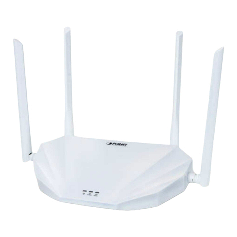
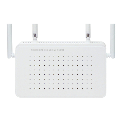
BHU NETWORKS BXM5 User manual

BHU NETWORKS®BXM2/5
User Manual
Version No.V2.1
Beijing Huasun Unicreate Technology Co., Ltd.

The customers could contact the local BHU branch office or headquarter directly to
get comprehensive technical support from Beijing Huasun Unicreate Technology Co.,
Ltd. Please download the electronic product user manual from official website.
Beijing Huasun Unicreate Technology Co., Ltd.
Headquarter Address:Huizhi Office Building, No.9-6 Xueqing Road, Haidian District
Official Website:www.bhunetworks.com/overseas
Customer Service hotline:86-10-82730100
Customer Service Mailbox:bhu@bhunetworks.com

BHU NETWORKS®BXM2/5 User Manual
Version No.V2.1
i
Copyright Declaration
Beijing Huasun Unicreate Technology Co., Ltd. All ri ghts reserved. Beijing Huasun
Unicreate Technology Co., Ltd. reserves the final interpretation and revision right of
this user manual without any prior notice.
This ve rsion rig ht o f user manu al belong s to Beijing Huasun Unicreate Technology
Co., Ltd. Any form o f behavior, including reproduction, excerpti on, copy, revision,
distribution, translation of any part of the contents in this document without the prior
written permission of Beijing Huasun Unicreate Technology Co., Ltd. is prohibited.
Disclaimer
This user manual is based on data available and herein update contents can be made
without notice. Beijing Huasun Unicreate Technology Co., Ltd., has tried its best to
ensure the accuracy and reliability of this user manual, but do not claim for the loss
or damage caused by any omission, inaccuracy or error in this user manual.

BHU NETWORKS®BXM2/5 User Manual
Version No.V2.1
ii
Introduction of user manual
Audience
Objectives: This manual provides guidelin es for people who purchase, use, manage
and maint ain BHU N ETWORKS®BXM2/5 serial produc t and thos e enterpris es and
relevant personnel who involved in constructing network system, such as engineers,
technicians, product and R&D personnel, as well as other users of this product.
This manual as a quick config urations an d training guide, is suitable for BHU
NETWORKS®BXM2/5 series product initial user, common and proficient operator.
Summary
This manual gives a brief and focused e xplanation to B HU NETWORKS ®BXM2/5
series product in the following aspects: the user i nterface, q uickly cons tructing
network c onfiguration software, configu ration method of login, the function o f
important parameters and its effect, as well as some other points for attentions.
You can us e this manual to complete rapid configurat ion, meet quick and typical
networking needs and complete the main applications.
Technical Service Support
Beijing Huasun Unicreate Technology Co., Ltd. (Hereinafter referred as BHU
Networks) set up the service system base d on the headquarter technology center,
The customers could contact BHU Networks service hot line whenever has trouble in
using th e product and runni ng the network. Please access
www.bhunetworks.com/overseasfor service support hot line numbers.
In addition, customers can also get the latest product news and download the
required technical documentations from the BHU Networks website.

Contents
iii
Contents
1Product Overview......................................................................................................................................... 1
1.1Product Overview........................................................................................................................................ 1
1.2 Main Feature.................................................................................................................................................. 1
2Product Composition.................................................................................................................................. 2
2.1Packing list .................................................................................................................................................... 2
2.2System Composition .................................................................................................................................. 3
2.2.1Panel Layout........................................................................................................................................3
2.2.1.1Indicator Indication ..........................................................................................................................3
2.2.1.2Interface Indication ..........................................................................................................................4
2.3Common Button .......................................................................................................................................... 5
2.3.1Navigation Bar Group Button........................................................................................................5
2.3.2Main Menu Group Button................................................................................................................5
2.3.3 Application Change Button .............................................................................................................5
2.3.4Save Button.........................................................................................................................................6
3Installation and Settings......................................................................................................................... 7
3.1Pre-installation............................................................................................................................................. 7
3.2 Installation Guidance.............................................................................................................................. 8
3.3 Configuration Guidance............................................................................................................................. 9
3.3.1WEB Interface Settings...................................................................................................................9
3.4Configuration Wizard ............................................................................................................................... 10
3.4.1Select Bridge-AP Mode ..................................................................................................................10
3.4.2 Select Bridge-Station Mode..........................................................................................................14
3.4.3Select Bridge-Repeater Mode .....................................................................................................16
3.4.4Select Router-AP Mode..................................................................................................................19
3.4.5Select Router-Station Mode ........................................................................................................23
3.4.6Select Router-Repeater Mode.....................................................................................................26
3.5Wireless Settings....................................................................................................................................... 31
3.5.1RF Settings ........................................................................................................................................31
3.5.2Virtual AP Settings..........................................................................................................................33
3.5.3Advanced Settings ..........................................................................................................................34
3.5.4Status ..................................................................................................................................................35
3.5.5Traffic Control...................................................................................................................................35
3.6Network Settings....................................................................................................................................... 36
3.6.1LAN Settings......................................................................................................................................36
3.6.2 WLAN Settings..............................................................................................................................37
3.6.3Client List............................................................................................................................................39
3.6.4Router Settings ................................................................................................................................40
3.6.5 Equipment Reset ..............................................................................................................................42
3.6.6DMZ Area Settings..........................................................................................................................42
3.6.7NAT Settings .....................................................................................................................................43
3.6.8 uPnP Settings.....................................................................................................................................43
3.7System Configuration.............................................................................................................................. 44
3.7.1System Settings...............................................................................................................................44
3.7.2Restore Factory Configuration....................................................................................................45
3.7.3Reboot or Version Upgrade .........................................................................................................46
3.7.4User Administration........................................................................................................................46
3.7.5System Tool.......................................................................................................................................48
3.7.6System Time Settings ...................................................................................................................48
3.7.7Administration Interface...............................................................................................................49
3.7.8System Log........................................................................................................................................51
4Maintenance Overview............................................................................................................................ 52
4.1Common Tools of Maintenance............................................................................................................ 52

Contents
iv
4.2Maintenance Personnel Requirement................................................................................................ 52
5Equipment Check and Troubleshooting......................................................................................... 53
5.1The correct installation and configuration of BXM2/5 equipment .......................................... 53
5.2Network Checking and Troubleshooting........................................................................................... 57
5.3 FAQ and Solutions..................................................................................................................................... 58
6Appendix.......................................................................................................................................................... 59
6.1Technical Parameters .............................................................................................................................. 59
6.2 Glossary ...................................................................................................................................................... 63

List of Figures
v
List of Figures
Figure 1 Indicator Panel ............................................................................................................... 3
Figure 2 Equipment Interface and Reset Button ................................................................ 4
Figure 3 Navigation Bar................................................................................................................ 5
Figure 4 Menu .................................................................................................................................. 5
Figure 5 Application Change Button....................................................................................... 5
Figure 6 Save Button..................................................................................................................... 6
Figure 7 Login page...................................................................................................................... 9
Figure 8 System Status ............................................................................................................ 10
Figure 9 Bridge-AP Mode.......................................................................................................... 10
Figure 10 Bridge-AP Mode ....................................................................................................... 11
Figure 11 Bridge-AP Mode ....................................................................................................... 11
Figure 12 Bridge-AP Mode...................................................................................................... 12
Figure 13 Bridge-AP Mode ....................................................................................................... 12
Figure 14 Bridge-AP Mode ....................................................................................................... 13
Figure 15 Bridge-AP Mode ....................................................................................................... 13
Figure 16 Bridge-Station Mode................................................................................................ 14
Figure 17 Bridge-Station Mode .............................................................................................. 14
Figure 18 Bridge-Station Mode................................................................................................ 15
Figure 19 Bridge-Station Mode................................................................................................ 15
Figure 20 Bridge-Station Mode .............................................................................................. 16
Figure 21 Bridge-Station Mode................................................................................................ 16
Figure 22 Bridge-Repeater Mode............................................................................................ 17
Figure 23 Bridge-Repeater Mode............................................................................................ 17
Figure 24 Bridge-Repeater Mode............................................................................................ 17
Figure 25 Bridge-Repeater Mode............................................................................................ 18
Figure 26 Bridge-Repeater Mode............................................................................................ 18

List of Figures
vi
Figure 27 Bridge-Repeater Mode............................................................................................ 19
Figure 28 Bridge-Repeater Mode............................................................................................ 19
Figure 29 Router-AP Mode ........................................................................................................ 20
Figure 30 Router-AP Mode ........................................................................................................ 20
Figure 31 Router-AP Mode ........................................................................................................ 20
Figure 32 Router-AP Mode ........................................................................................................ 21
Figure 33 Router-AP Mode ........................................................................................................ 21
Figure 34 Router-AP Mode ........................................................................................................ 22
Figure 35 Router-AP Mode ........................................................................................................ 22
Figure 36 Router-AP Mode ........................................................................................................ 23
Figure 37 Router-Station Mode ............................................................................................... 23
Figure 38 Router-Station Mode ............................................................................................... 23
Figure 39 Router-Station Mode ............................................................................................... 24
Figure 40 Router-Station Mode ............................................................................................... 24
Figure 41 Router-Station Mode ............................................................................................... 25
Figure 42 Router-Station Mode ............................................................................................... 25
Figure 43 Router-Station Mode ............................................................................................... 26
Figure 44 Router-Station Mode ............................................................................................... 26
Figure 45 Router-Repeater Mode ........................................................................................... 27
Figure 46 Router-Repeater Mode ........................................................................................... 27
Figure 47 Router-Repeater Mode ........................................................................................... 27
Figure 48 Router-Repeater Mode ........................................................................................... 28
Figure 49 Router-Repeater Mode ........................................................................................... 28
Figure 50 Router-Repeater Mode ........................................................................................... 29
Figure 51 Router-Repeater Mode ........................................................................................... 29
Figure 52 Router-Repeater Mode ........................................................................................... 30
Figure 53 Router-Repeater Mode ........................................................................................... 30

List of Figures
vii
Figure 54 RF Configuration ....................................................................................................... 31
Figure 55 RF Configuration Modification.............................................................................. 31
Figure 56 RF Configuration Modification.............................................................................. 32
Figure 57 RF Configuration Modification.............................................................................. 32
Figure 58 Virtual AP Settings ................................................................................................... 33
Figure 59 VAP Advanced Configuration................................................................................ 34
Figure 60 Advanced Configuration......................................................................................... 35
Figure 61 WLAN Status .............................................................................................................. 35
Figure 62 Traffic Control Settings .......................................................................................... 36
Figure 63 Add traffic control of user............................................................................. 36
Figure 64 LAN Configuration .................................................................................................... 37
Figure 65 WLAN Settings........................................................................................................... 38
Figure 66 WLAN Settings Example 1..................................................................................... 38
Figure 67 WLAN Settings Example 2..................................................................................... 39
Figure 68 Route ACL Settings.................................................................................................. 41
Figure 69 Edit Router Transfer Control Rule ...................................................................... 41
Figure 70 Rule Settings.............................................................................................................. 41
Figure 71 DMZ Area Settings................................................................................................... 42
Figure 72 NAT Settings............................................................................................................... 43
Figure 73 UPnP Settings............................................................................................................. 43
Figure 74 Configuration Administration ............................................................................... 44
Figure 75 Restore Factory Settings ....................................................................................... 46
Figure 76 Restart Configuration.............................................................................................. 46
Figure 77 Upgrade Firmware.................................................................................................... 46
Figure 78 User Management .................................................................................................... 47
Figure 79 New User...................................................................................................................... 47
Figure 80 Add New User ............................................................................................................ 48

List of Figures
viii
Figure 81 System Tool................................................................................................................ 48
Figure 82 Management Configuration .................................................................................. 50
Figure 83 Log Management ...................................................................................................... 51
Figure 84 Equipment Installation ........................................................................................... 53
Figure 85 Indicator Panel .......................................................................................................... 54
Figure 86 RSSI Receiving Strength ....................................................................................... 55
Figure 87 Connecting Method .................................................................................................. 55

1 Product Overview
1 / 64
1 Product Overview
1.1 Product Overview
BHU Networks (hereinafter referred as BHU Networ ks) launc hes BHU
NETWORKS®BXM2/5 (BXM2/5 for short) on the basis o f proprietary space adaptive
optimal communication technology-- airX.
Supporting wireless route and bridging, BXM2 complies with 802.11bgn protocol and
works at 2.4GHz frequency range,BXM5 complies with 802.11an protocol and works
at 5GHz frequency ra nge. T hey both provi de high performance wireless relay lin k
among WLAN stations to ensure higher tr ansmission rate and longer transmission
distance. Enhanced network functions make them suitable for various application
conditions.
Easy installation and friendly configuration interface guarantee BXM2/5 product
quickly access to deployment and service. They aim to perfectly solve the problems
of termination access in WLAN coverage area or marginal area, at the same time
extends the coverage of WLAN stations as large as possible. Transmit power no
longer stops BXM2/5 from covering widely due to its 500mW transmit power and
high-gain antenna in 12dBi of BXM2 & 16dBi of BXM5.
1.2 Main Feature
Uplink to 2.4GHzof BXM2 & 5GHz of BXM5. wireless access point, downlink to
dual-wire LAN port export;
Wireless access support IEEE 802.11b/g/n standard of BXM2 & 802.11a/n
standard of BXM5;
Support MIMO 2x2, maximum rate up to 300Mbps;
Support respective user’s independent authentication under WDS bridging mode;
Max transmit power up to 500Mw, maximum receiver sensitivity up to
-100dBm of BXM2 & -95dBm of BXM5, both substantially ensure long transmission
distance and high quality signal of wireless link;
Support 2x Ethernet ports in main and auxiliary backup use, or independent use;

2 Product Composition
2 / 64
2 Product Composition
2.1 Packing list
Table 1
No. Name Quantity (Unit)
1. Packing Box 1(pc)
2. BXM2/5 1(pc)
3. POE Power Supply Module 1(pc)
4. Cable Ties 2(pcs)

2 Product Composition
3 / 64
2.2 System Composition
2.2.1 Panel Layout
2.2.1.1 Indicator Indication
Figure 1 Indicator Panel
Table 2
No. Indicator Description Function
1PWR
Power Indicator
(Yellow)
Long out-Power-off
Long bright-Power-on
2LAN
Ethernet Indicator
Left port is primary
port
Right port is secondary
port
Always off-AP mode
Always bright-Station、Repeater
mode
3MODE Signal Lamp
Station mode-the last three lamps
stand for signal strength .
Repeater mode-the last three lamps
stand for signal strength.
AP mode-the last three lamps light.

2 Product Composition
4 / 64
2.2.1.2 Interface Indication
Figure 2 Equipment Interface and Reset Button
Table 3
No. Interface Name Description
1. 1/2/(Primary/Secondary)
Ethernet t erminal plug (RJ45), only
Primary is used fo r PoE power
supply.
2. Reset
After starting up the equipment,
press the reset key for 5 seconds to
restore the factory Configuration.
When the equipment power is
switched on, press the reset key for
10 seconds to restore factory
Configuration and supply first aid to
procedures http.
3. Antenna Build-in antenna, for sending and
receiving wireless data.

2 Product Composition
5 / 64
2.3 Common Button
2.3.1 Navigation Bar Group Button
The navigation bar has three group buttons: cancel, save and he lp. When using the
respective functions of th e e quipment, please click t he help button and m ake the
configurations according to the page tips. As it is shown in the figure below:
Figure 3 Navigation Bar
Note:Click “Save”, to prevent the configuration loss.
2.3.2 Main Menu Group Button
There are five groups of buttons in differe nt kind s o f fun ctions, as shown in the
figure below:
Figure 4 Menu
2.3.3 Application Change Button
Figure 5 Application Change Button
Note:Once finish the configurations, the current page comes into effect.

2 Product Composition
6 / 64
Note:Need to reboot the equipment to make some parameters effective (refer to
page instruction).
2.3.4 Save Button
Figure 6 Save Button
Note:After change the application, please click “save” to prevent the equipment
from losing the current configuration after equipment reboot.

3 Installation and Settings
7 / 64
3 Installation and Settings
3.1 Pre-installation
Table 4
No. Name Quantity
(unit) Remarks
1. BXM2/5 1(pc) /
2.
POE Power Supply Module
Type:BA-2408P
Input voltage:AC100-240V
50/60Hz
Output voltage:DC24V-800mA
1(pc) /
3. Cable Ties 2(pcs) /
4. Ethernet Cables 2(pcs) Self-contained
5. Holding Pole 1(pc) Self -contained

3 Installation and Settings
8 / 64
3.2 Installation Guidance
The installation procedures is as shown in the figure below :
Step 1 :Pre-installation. Please refer to
Table 4 for all accessories.
Step 2 :Press hard on coupler with your
fingers and pull out the back cover slides
from the slot.
Step 3 :PoE port locates at the left of
PoE module, LAN port locates at the
right, Primary port lo cates at the left of
BXM2/5, Secondary port locates at the
right, Reset button locates in the middle.
Step 4 :Supply power to the equipment,
connect to PC , and fix BXM2/5 to the
holding pole by using the cable ties.
Note :Link PoE port to CPE Primary port,
and link LAN port to the laptop LAN port.
Step 5 :The equipm ent is inst alled and
switched on, and t he indicat or lights
normally. According to indicator
direction: Station mo de, the thi rd lamp
lights up, the last three indicators display
BXM2/5 signal strength.
Step 6:Set parameter via Web interface.
Default IP address: 192.168.1.1
Default Subnet Mask: 255.255.255.0
Default User ID: admin
Default Login password: admin
For web i nterface c onfiguration details,
please logi n official w ebsite to download
BXM2/5 user manual:
http://www.bhunetworks.com/overseas
IndicatorDirection

3 Installation and Settings
9 / 64
3.3 Configuration Guidance
3.3.1 WEB Interface Settings
When logi n the equi pment, the default IP address :192.168.1.1;subnet mask :
255.255.255.0
User ID and password is needed for log i n the WEB , default user name: admin;
password: admin.
Once finish the password settings, click “login” button to jump to login page.
Note:Support language switch between Chinese and English.
Figure 7 Login page

3 Installation and Settings
10 / 64
3.3.2 Running Status
Click “Main Page”, jump to eq uipment information page, includi ng network status ,
WLAN status, system status and equipmen t info rmation, as shown in the figure
below:
Figure 8 System Status
3.4 Configuration Wizard
3.4.1 Select Bridge-AP Mode
Bridge-AP: Bridge-Access Point Mode. WLAN as AP, can be connected with the
Ethernet.
Open “Configuration→Configuration Wizard”, as shown in the figure below:
Figure 9 Bridge-AP Mode
Click “Next” to select work mode, as shown in the figure below:
This manual suits for next models
1
Table of contents
