manuals.online logo
Brands
  1. Home
  2. •
  3. Brands
  4. •
  5. Biamp
  6. •
  7. Extender
  8. •
  9. Biamp IMPERA CONNECT-X MP6 Assembly instructions

Biamp IMPERA CONNECT-X MP6 Assembly instructions

Other Biamp Extender manuals
Biamp AudiaEXPI-D User manual

Biamp

Biamp AudiaEXPI-D User manual

Biamp Audia EXPI User manual

Biamp

Biamp Audia EXPI User manual

Biamp Vocia VO-4e User manual

Biamp

Biamp Vocia VO-4e User manual

Biamp Tesira EX-UBT User manual

Biamp

Biamp Tesira EX-UBT User manual

Biamp AudiaEXPI-4 User manual

Biamp

Biamp AudiaEXPI-4 User manual

Biamp Tesira EX-LOGIC User manual

Biamp

Biamp Tesira EX-LOGIC User manual

Biamp Audia EXPI User manual

Biamp

Biamp Audia EXPI User manual

Biamp PARLE N 100 Assembly instructions

Biamp

Biamp PARLE N 100 Assembly instructions

Biamp Vocia VO-4 User manual

Biamp

Biamp Vocia VO-4 User manual

Biamp Tesira EX-UBT User manual

Biamp

Biamp Tesira EX-UBT User manual
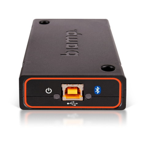
Biamp Tesira EX-LOGIC User manual

Biamp

Biamp Tesira EX-LOGIC User manual

Biamp Tesira EX-MOD User manual

Biamp

Biamp Tesira EX-MOD User manual

Biamp Tesira EX-AEC User manual

Biamp

Biamp Tesira EX-AEC User manual

Biamp TesiraCONNECT Original operating instructions

Biamp

Biamp TesiraCONNECT Original operating instructions

Biamp TesiraCONNECT TC-5D Original operating instructions

Biamp

Biamp TesiraCONNECT TC-5D Original operating instructions

Popular Extender manuals by other brands

Paugge ENT-EXT20B user manual

Paugge

Paugge ENT-EXT20B user manual

REIGN XRE-100 manual

REIGN

REIGN XRE-100 manual

Lindy 42805 user manual

Lindy

Lindy 42805 user manual

Digi ConnectPort Network Device user manual

Digi

Digi ConnectPort Network Device user manual

British General N300 instructions

British General

British General N300 instructions

VPI ST-WLHDMI-L-30M Installation and operation manual

VPI

VPI ST-WLHDMI-L-30M Installation and operation manual

Gefen EXT-DIGAUD-141 user manual

Gefen

Gefen EXT-DIGAUD-141 user manual

AMX netlinx NXC-MPE Dimensional drawing

AMX

AMX netlinx NXC-MPE Dimensional drawing

SY HDBT-60T installation guide

SY

SY HDBT-60T installation guide

Appsys ProAudio ADX-16 user manual

Appsys ProAudio

Appsys ProAudio ADX-16 user manual

Atlona RS232 user manual

Atlona

Atlona RS232 user manual

IDK OPF-TH1000-A user guide

IDK

IDK OPF-TH1000-A user guide

Enable-IT 824WP quick start guide

Enable-IT

Enable-IT 824WP quick start guide

Worx Landroid RadioLink WA0864 Get started

Worx

Worx Landroid RadioLink WA0864 Get started

TP-Link TL-WA730RE user guide

TP-Link

TP-Link TL-WA730RE user guide

Camplex CMX-HDMI-SFPL user manual

Camplex

Camplex CMX-HDMI-SFPL user manual

SC&T HE03-4K user manual

SC&T

SC&T HE03-4K user manual

Samsung SCS-26UC4 user guide

Samsung

Samsung SCS-26UC4 user guide

manuals.online logo
manuals.online logoBrands
  • About & Mission
  • Contact us
  • Privacy Policy
  • Terms and Conditions

Copyright 2025 Manuals.Online. All Rights Reserved.

[email protected] www.biamp.com
IMPERA
INCLUDED IN THE BOX
INSTALLATION CONSIDERATIONS
CONNECT-X MP6
EXTENSION DEVICE
INSTALLATION AND SET UP GUIDE
• The Connect-X MP6 is an extension device that provides serial, IR, GPIO ports, as
well as LAN control.
• The device may be installed in various locations using the built-in mounting system
that allows the device to be securely fastened on or under desktops, on walls,
equipment racks, or tied to cables, etc.
• PoE powered: use an IEEE 802.3 - compliant PoE power supply of switch. PoE
injector is not included.
2
Installation & Set Up Guide
DEVICE LAYOUT
FRONT PANEL LAYOUT
REAR PANEL LAYOUT
1. 1 Power LED indicator
2. 1 Status LED indicator
1. 1 RJ-45 Network (LAN) port with PoE functionality
2. 1 Factory reset recessed pin-hole button
3. 2 RS-232 or IR terminal, unidirectional
4. 1 RS-232 terminal, bidirectional or IR unidirectional
5. 3 Digital Input / Output port
6. 1 mini USB conguration port
REAR PANEL PORTS AND TERMINALS
2 3 4 5 61
2
1
FRONT PANEL INDICATORS
3
Installation & Set Up Guide
2
INSTALLATION
Install on a at surface using the screw hole mounts. These allow for the device to
be mounted in a varity of locations such as under a table or on a wall.
1. Determine the location where the device will be located and verify the surface
is at enough for the device to be mounted.
2. Install the device in the desired location with the provided hardware.
OPTION 1
Install in a location without a at surface by using zip ties in the guide slots. These
allow for the device to be secured to equipment racks, cables, cords, or in places
where screws would not be an option.
1. Determine the location where the device will be located.
2. Thread a zip tie through a guide slot and keep the device against the object
that it will be secured to.
OPTION 2
4
Installation & Set Up Guide
INSTALLATION
3. Loop the pointed end of the zip tie around what the device will be secured to
and then back through the guide slot.
4. Insert the the pointed end of the zip tie into the locking mechanism until it
clicks. Keeping the ties loose enough to adjust the postion of the device.
5. Repeat this process for the other guide slot.
6. Adjust the location of the device as needed before tightening the zip ties
enough to secure the device in place.
5
Installation & Set Up Guide
4
POWER AND STATUS INDICATORS
O:
The device is not
powered
Green:
The device is
powered
O:
The device is not
powered
Solid Green:
No errors
Flashing Green:
Device is powering
up
Solid Amber:
Firmware version
dierent than
host controller
Flashing Amber:
Factory reset in
progress
Solid Red:
An unexpected
error has occured
Flashing Red:
Unable to connect
to host controller
POWER LED INDICATOR
STATUS LED INDICATOR
6
Installation & Set Up Guide
CONNECTION CONFIGURATIONS
Bidirectional RS-232 communications example.
Ground to Pin 5
Tx-1 to Pin 3
Rx-1 to Pin 2
CONNECTIONS
The TX and RX termials can be congured as either RS-232 or IR emitter ports using
the Biamp Project Designer software.
RS-232 / IR TERMINALS
One-Way Communicatons: The TX-3 and TX-2 are unidriectional
transmit terminals.
Two-Way Communications: The TX-1 and RX-1 terminals make up a bidirectional
transmit and receive terminal. This can be connected to devices requiring a reply
function such as projectors.
7
Installation & Set Up Guide
6
CONNECTIONS
RS-232 unidirectional transmit port example.
Ground to Pin 5
Tx-2 to Pin 2
Single IR port unidirectional transmit example.
IR Emitter
Ground to IR Emitter
Tx-2 striped wire to IR Emitter
8
Installation & Set Up Guide
Dual IR port example.
CONNECTIONS
IR 2 Emitter
IR 1 Emitter
Junction
Ground to IR 2 Emitter
TX-2 to IR 1 Emitter
9
Installation & Set Up Guide
8
Inputs:
• When used as inputs, the applied voltage must be below 1 VDC to be accepted as
LOW, and above 4 VDC (but below 24 VDC) to be accepted as HIGH.
• The inputs are default HIGH and must be connected to a ground to change state.
Potential: These ports are not potential-free. External relays may be needed to prevent
ground loops depending on the application.
Outputs:
• When used as outputs, the I/O ports are active low.
• When activeted, the I/O ports are tied to GND through a FET transistor. Also known
as an open drain or collector function.
• Each I/O can draw up to 24DC/500mA.
CONNECTIONS
INPUT / OUTPUT PORTS (I/O)
The controller has 3 general ports that are each congured as either output or input.
Each of these I/O ports is available for connection to devices such as:
• A PIR movement sensor
• A keyboard lock
• Relays
• Other compatible uses
10
Installation & Set Up Guide
CONNECTIONS
ETHERNET PORT (LAN)
The RJ-45 Network (LAN) connector with PoE functionality is used for:
• Power over Ethernet
• Connecting to a host controller
• Configuring and controlling third-party devices over a network
Port LED indicators: The yellow LED indicates the link status and the green LED indicates
the link speed.
Power over Ethernet (PoE)
This port provides power over Ethernet to the controller. Powering the controller requires
one of the following:
• A PoE-enabled switch compliant with an IEEE 802.3
• A PoE power injector compliant with IEEE 802.3
LED Color Light O Light On Light Blinking
Yellow No Link Link Activity
Green 10 Mbit 100 Mbit