manuals.online logo
Brands
  1. Home
  2. •
  3. Brands
  4. •
  5. Biamp
  6. •
  7. Extender
  8. •
  9. Biamp Tesira EX-LOGIC User manual

Biamp Tesira EX-LOGIC User manual

Tesira Logic
Expander (EX-LOGIC)
OPERATION MANUAL
April 2019
EX-LOGIC PRODUCT DESCRIPTION
The Tesira® EX-LOGIC is a half-rack logic box for use with Tesira SERVER and SERVER-IO devices. The
EX-LOGIC provides both logic inputs and outputs and, through software, can be configured as a control
interface. There are 16 total connections that can be used as inputs or outputs. 12 of the connections are
designed as logic connections only and will accept contact closure or 5V TTL when used for logic or sink a
maximum of 40V/300mA per output. The remaining four connections can also be used for logic connections
or as variable voltage control inputs (e.g. interface to a potentiometer). Additionally, any of the 16 connections
can be configured for direct LED driver capability. The EX-LOGIC also provides a serial port for the output
of command strings that can be used to send action commands to other equipment in the system. The
EX-LOGIC communicates with the Tesira network for data transmission, configuration and control, and
is powered by PoE.
EX-LOGIC FRONT PANEL
Setup and Use
The Tesira software provides an intuitive interface for setup and programming of the EX-LOGIC. The information supplied
by this manual relates to physical connections and device setup. For more details on software setup, please consult the
Tesira Help File.
LED Status Indicators
Four multi-color LEDs on the front panel of the device provide information about the status of the device and the greater
Tesira system.
•Power – Reports power of the host device and Front Panel Display.
•Alarm – Reports abnormal conditions local to the host device.
•Activity – Reports the activity of host device within the greater system.
•Status – Reports the status of host device.
LED Off Green Yellow Red
Power
Unit is not powered
Unit is powered
Not applicable
Not applicable
Alarm
No fault is active in the
device
Not applicable
Minor fault is active in
the device
Major fault is active
in the device
Activity
Not applicable
The host device is an
active part of an active
system
Not applicable
The host device is part
of an inactive system
(Audio is stopped) or
host device is not part
of a system
Status
Not applicable
Device has received its
configuration and is ready
to participate in the system
Device is ready and
waiting to receive a
configuration
Device is not ready to
receive its configuration
EX-LOGIC REAR PANEL
Connectors
1. Grounding pin
This pin is for grounding the chassis of the expander
2. Ethernet data connection
A standard RJ-45 connector for use with CAT-5, CAT-5e, CAT-6 or
CAT-7 cabling. The maximum distance between any unit and an Ethernet switch is 328 feet (100
meters). The expander must receive PoE (IEEE 802.3af) power on this connector in order for
proper operation.
This connection is for sending and receiving control data with the Tesira server. The expander will
not operate if it is not on a network that includes a Server-Class Tesira device.
3. Serial Control port
The serial port can be utilized to send a control string to another device.
4. Connections 1-to-12
These GPIO connections can be used as either inputs or outputs. They can
be assigned to actions within the software using Logic Input and Logic Output blocks.
When configured as logic output, each of the 16 GPIO pins can be configured to enable a current
source capable of driving an LED. The current source is enabled depending on the state of the logic
output block.
5. Connections 13-to-16
These connections can function in the same way as connections 1-12
for digital GPIO. But they can also be assigned as variable voltage input controls to allow analog
control within the Tesira system by connection to a potentiometer.
GPIO pins 13–16 can be configured individually by the Control Voltage block in the software. If
any one of these is configured for voltage control, then the logic expander will turn on the 5V
potentiometer power.
Voltage Control Calibration
The four analog GPIO pins support voltage control calibration because a potentiometer may not be
able to achieve the full range of voltage expected by the internal analog/digital convertors. When
calibrated, the logic expander records both the minimum and maximum voltage levels caused by
the potentiometer to achieve the full range of voltage. A 10K Linear Potentiometer or similar value
is suggested.
Visit www.biamp.com to obtain firmware and software updates related to this product. To speak with an Applications
Engineer, please call 1.503.641.7287 or email support@biamp.com.

Other manuals for Tesira EX-LOGIC

1

Other Biamp Extender manuals

Biamp Tesira EX-AEC User manual

Biamp

Biamp Tesira EX-AEC User manual

Biamp AudiaEXPI-4 User manual

Biamp

Biamp AudiaEXPI-4 User manual

Biamp IMPERA CONNECT-X MP6 Assembly instructions

Biamp

Biamp IMPERA CONNECT-X MP6 Assembly instructions

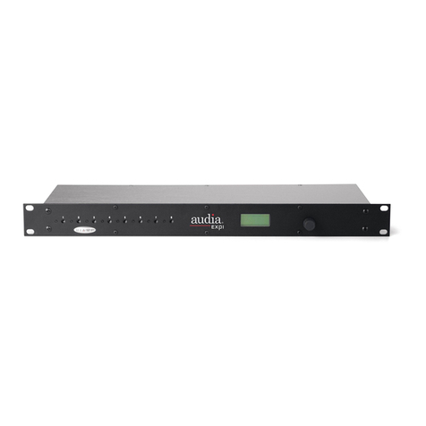
Biamp Audia EXPI User manual

Biamp

Biamp Audia EXPI User manual

Biamp AudiaEXPI-D User manual

Biamp

Biamp AudiaEXPI-D User manual

Biamp Vocia VO-4 User manual

Biamp

Biamp Vocia VO-4 User manual

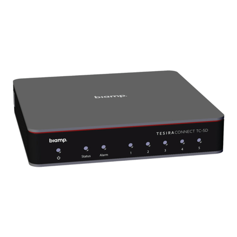
Biamp TesiraCONNECT TC-5D Original operating instructions

Biamp

Biamp TesiraCONNECT TC-5D Original operating instructions

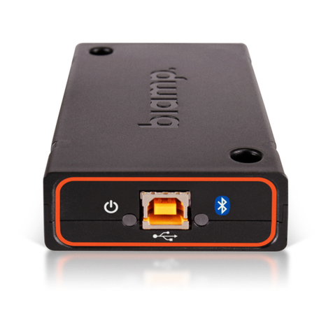
Biamp Tesira EX-UBT User manual

Biamp

Biamp Tesira EX-UBT User manual

Biamp Tesira EX-MOD User manual

Biamp

Biamp Tesira EX-MOD User manual

Biamp Audia EXPI User manual

Biamp

Biamp Audia EXPI User manual

Biamp Vocia VO-4e User manual

Biamp

Biamp Vocia VO-4e User manual

Biamp PARLE N 100 Assembly instructions

Biamp

Biamp PARLE N 100 Assembly instructions

Biamp Tesira EX-LOGIC User manual

Biamp

Biamp Tesira EX-LOGIC User manual

Biamp TesiraCONNECT Original operating instructions

Biamp

Biamp TesiraCONNECT Original operating instructions

Biamp Tesira EX-UBT User manual

Biamp

Biamp Tesira EX-UBT User manual

Popular Extender manuals by other brands

Avenview FO-DVI-DL-330X user guide

Avenview

Avenview FO-DVI-DL-330X user guide

zBoost YX520 Imternational user guide

zBoost

zBoost YX520 Imternational user guide

SC&T DKM01 manual

SC&T

SC&T DKM01 manual

zBoost ZB545 Setup overview

zBoost

zBoost ZB545 Setup overview

TIS TSV-EX22 manual

TIS

TIS TSV-EX22 manual

Gefen GEF-3GSDI-FO-141 user manual

Gefen

Gefen GEF-3GSDI-FO-141 user manual

Straightpoint SW-SB user manual

Straightpoint

Straightpoint SW-SB user manual

Gefen PCX150 user manual

Gefen

Gefen PCX150 user manual

NETGEAR EX6920 user manual

NETGEAR

NETGEAR EX6920 user manual

Motorola SIGNAL BOOSTER - WARRANTY Limited warranty

Motorola

Motorola SIGNAL BOOSTER - WARRANTY Limited warranty

SolidView PS-691 user manual

SolidView

SolidView PS-691 user manual

BIRD Signal Booster II+ Installation and operation manual

BIRD

BIRD Signal Booster II+ Installation and operation manual

Foresight CCTV Active Series manual

Foresight CCTV

Foresight CCTV Active Series manual

Hank Electronics Co., Ltd. HKW001EUS1 operating instructions

Hank Electronics Co., Ltd.

Hank Electronics Co., Ltd. HKW001EUS1 operating instructions

D-Link Covr Simple setup guide

D-Link

D-Link Covr Simple setup guide

TP-Link RE300 Quick installation guide

TP-Link

TP-Link RE300 Quick installation guide

Cisco SCE 2000 quick start guide

Cisco

Cisco SCE 2000 quick start guide

Renkforce RF-4600990 operating instructions

Renkforce

Renkforce RF-4600990 operating instructions

manuals.online logo
manuals.online logoBrands
  • About & Mission
  • Contact us
  • Privacy Policy
  • Terms and Conditions

Copyright 2025 Manuals.Online. All Rights Reserved.