Bianchi REPARTO CORSE WHEELS Operating instructions

REPARTO CORSE WHEELS
USER AND MAINTENANCE MANUAL
C8005102 | 2023


3
INDEX
ENGLISH 5
ITALIANO 15
DEUTSCH 25
FRANÇAIS 35
ESPAÑOL 45
日本語 55

4

5
REPARTO CORSE WHEELS
USER AND MAINTENANCE MANUAL
BUILDER/MANUFACTURER
Reparto Corse wheels (hereinafter referred to as ‘Wheel(s)’ or ‘Product’) are made/manufactured by:
F.I.V.E. BIANCHI S.p.A. - Via delle Battaglie, 5 -24047 Treviglio (BG) - Web: www.bianchi.com (hereinafter referred to as ‘Manufacturer’)
Precision, performance and style. Congratulations on pairing your bike with this spectacular wheelset. Disc brake-ready and with an aerodynamic
profile, it’s time to ride the perfect lines at the optimum speed.
GENERAL ASPECTS
It is imperative that all users carefully read, understand, and follow the instructions in this user and maintenance manual before using Reparto
Corse wheels. The user remains responsible for damage caused to persons and/or property and to the Wheels if they are used incorrectly or not in
accordance with the instructions below.
This manual is an integral part of the wheels and should be kept for any future reference.
RESPONSIBILITY
Failure to comply with the operating instructions and safety requirements contained in this user and maintenance manual shall exempt the
Manufacturer from any liability.
The Manufacturer is also indemnified from any liability, including but not limited to personal safety, in the event that the use and maintenance of the Wheels
are performed in a manner not in accordance with the instructions provided, and/or that the Wheels are used incorrectly or in such a way as to impair
their integrity and/or change their characteristics, and/or non-original spare parts are used, and/or the Wheels are not properly installed on the bicycle.
SPECIFIC SKILLS
This manual is intended for the Wheel user. It includes instructions regarding maintenance and care of the Wheels. Most of the Wheels’ maintenance
and repair require specific knowledge and proper equipment. If the user does not have the required specific skills and/or proper equipment, it is
recommended that the user seek professional personnel or a Bianchi dealer.
LEGEND
WARNING/SAFETY RULE
It indicates basic safety standards and rules. Failure to follow these rules may result in accidents, falls, injury to the user and to other people.
CAUTION/IMPORTANT
Signals important technical warnings to be strictly followed for the purpose of proper use of the Wheels.
TECHNICAL SPECIFICATIONS
Table 1.
FRONT REAR
AXLE Ø12 x 100 mm Ø12 x 142 mm
FREEWHEEL BODY
SHIMANO HG-11
SRAM XDR
CAMPAGNOLO N3W
ADHESIVE ANTI-VIBRATION VALVE Code DBU22081 *
VALVES H profile < 45 mm 45 mm < H profile < 60 mm H profile > 60 mm
Code C4805266 (L=60 mm) * Code C4805267 (L=80 mm) * Code C4805268 (L=100 mm) *
*Components only available in kit form
EN
6
QUALITY STANDARDS
The Wheels have been checked according to the Manufacturer’s quality standard and tested in accordance with the industry standard
UNI EN 4210-7.
DESIGNATED INTENDED USE ASTM
CAUTION/IMPORTANT
The wheels are designed for exclusive use:
a) on bicycles with disc brakes and without a motor.
b) in the following categories: 1 and/or 2 and in the less severe category as defined by the ASTM (American Society for Testing and
Materials) standards, which take into account the stresses that the wheels themselves may face and the vehicles on which they may
be used.
(hereinafter, use (a) and (b) jointly referred to as “Designated Use”).
* ASTM category
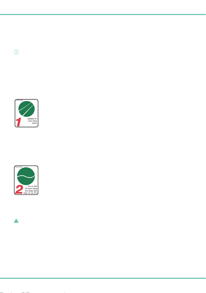
ASTM CATEGORY 1: Routes on paved roads. In short, this category includes all the
bikes and components, including wheels, designed for use on smooth surfaces, and where therefore
both tires remain in contact with the ground.
List of Reparto Corse wheels in the ASTM1 category
- RC 65R SPBTECH ETRTO 622 x 21C (Rear Code C4205982)
- RC 50R SPBTECH ETRTO 622 x 21C (Front Code C4105964)
- RC 50R ETRTO 622 x 21C (Front Code C4105984 / Rear Code C4206001)
- RC 33RCERAMITEC ETRTO 622 x 21C (Front Code C4105983 / Rear Code C4206121)
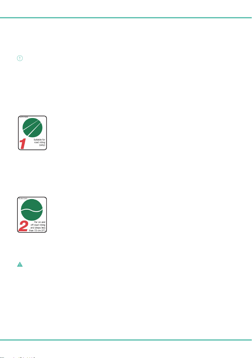
ASTM CATEGORY 2: Paved and off-road routes with drops of less than 15 cm.
This type of use includes bicycles and components that can be used in Category 1 or on dirt roads (gravel roads).
Whether on road or uneven terrain, loss of contact with the ground and the resulting jump and/or drop should not
exceed 15 cm in height.
It is therefore recommended that these wheels be used in the conditions for which they are intended or for less
severe conditions of use.
List of Reparto Corse wheels in the ASTM2 category
- RC 43CERAMITEC ETRTO 622 x 24C (Front Code C4106010 / Rear Code C4206137)
WARNING/SAFETY RULE
Any use of the Wheels other than Designated Use is prohibited.

7
SAFETY
WARNING/SAFETY RULE
All of the following directions are to be considered essential to ensure the safety of the user and of others.
1. The maximum allowable weight of the rider, their bicycle, and any accessories shall not exceed 120 kilograms.
2. Before each use, verify that the wheel is correctly installed by consulting the installation instructions provided by the bicycle or fork
manufacturer.
3. Before each use, verify that the tire pressure is correct and that there is no damage to the tire tread and/or sidewalls.
4. Check for damaged or loose spokes before each use.
5. Before each use, check the wheel centring by verifying that the wheel does not abnormally sway radially and/or laterally.
6. Before each use, check that the brake system is working properly.
7. Regularly check the wear of the brake pads and replace them if necessary.
8. Make sure the rotor does not touch the brake pads.
9. Do not exceed the maximum tire pressure indicated on the tire under any circumstances.
10. Do not exceed the maximum tire pressure tolerated by the rim and indicated on the rim itself under any circumstances.
11. The maximum allowable tire pressure is the lower number specified on the tire and specified on the rim.
12. The Wheels must be compatible with all bicycle parts.
13. The Wheels must not be modified or tampered with.
14. Check the Wheels for damage before and after each use.
15. If damage or signs of damage exist, the Wheels must not be used. If in doubt, contact your dealer.
16. Use only genuine Reparto Corse spare parts (check compatibility list in Tab.1).
BRAKES
Use the Wheels only on bicycles with a disc brake braking system.
WARNING/SAFETY RULE
DO NOT USE THE WHEELS WITH RIM BRAKE BRAKING SYSTEMS (CALLIPERS).
CAUTION/IMPORTANT
Danger of skin burns due to the high temperature of the brake rotor.
To avoid skin burns, it is important to allow the brake rotor to cool down before servicing the Wheels.
COMPONENTS AND TOOLS
CAUTION/IMPORTANT
Incorrect choice of components and/or tools can damage the Wheels.
DO NOT use metal tire levers. They can damage the rim, the tire, and even the inner tube.
TUBELESS READY SEALING TAPE
WARNING/SAFETY RULE
Worn or damaged Tubeless Ready sealing tape can cause a sudden loss of tire pressure.
CAUTION/IMPORTANT
Check the Tubeless Ready sealing tape at least every three months for wear.
Check the Tubeless Ready sealing tape after each tire change using a hard resin tire lever to verify its condition.
If there is damage or signs of damage and/or wear, the Wheels should not be used. If in doubt, contact your dealer or a professional
mechanic.

8
TUBELESS READY TAPE REPLACEMENT PROCEDURE
It is recommended that you strictly follow the instructions provided by the Tubeless Ready tire manufacturer as well as the following
general instructions if the Tubeless Ready sealing tape needs to be replaced:
1. Remove the tape previously affixed to the rim, using a tool (if necessary), such as a screwdriver, that allows the tape to be lifted and
removed without damaging the rim underneath.
2. Clean the inside of the rim (including the bed and walls) with a cloth soaked in isopropyl alcohol.
3. Apply the tubeless tape, spreading it anti-clockwise from the crankset side of the wheel (side opposite the brake rotor).
4. The tubeless tape should be stretched as it is applied. As a rule, it should not wrinkle or adhere to the rim bed, remaining centred/
symmetrical in relation to the width of the rim bed.
5. Apply the first strip of tubeless tape starting halfway between the second and third holes close to the valve bore, continue by
including the valve bore and then continue by making a complete loop until you reach the valve bore again.
6. After passing the valve hole for the second time, cut the tubeless tape at the second and third holes.
7. Using a cutter, cut an ‘X’ to open the valve bore on the tubeless tape.
8. Use the water hole on the side of the rim as a reference to align the cutter with the valve bore covered by the tubeless tape.
9. Proceed by cutting an X, with two separate movements, using a cutter with blade tip on the tape to make the first cut
10. Turning the cutter perpendicular to the previous cut, make the second cut. Make cuts carefully to avoid cutting through rim walls.
CAUTION/IMPORTANT
The entire surface of the tape must be fully bonded to the rim bed at the end of the process. Tape strips must not be raised or stuck
along the walls of the rim bed.
Cut the valve housing tape carefully to avoid cutting through rim walls.
If it is necessary to replace the sealing tape, use Reparto Corse replacement tape, together with the product in use specified in Table 2.
Table 2.
WHEEL TYPE ETRTO SIZE TAPE CODE
RC 65 SPBTECH ETRTO 622 x 21C C4605132 *
RC 50 SPBTECH ETRTO 622 x 21C C4605132 *
RC 50 ETRTO 622 x 21C C4605132 *
RC 33CERAMITEC ETRTO 622 x 21C C4605132 *
RC 43CERAMITEC ETRTO 622 x 24C C4605136 *
*Components only available in kit form
TUBELESS VALVE
The tubeless valve is supplied by the Manufacturer. When replacing the tubeless valve, it is recommended to use genuine Reparto Corse
spare parts (part number specified in Table 1).
CAUTION/IMPORTANT
Use only valves with a suitable length and diameter. See technical specification table (Table 1).
Do not modify the valve bore.
Periodically check the tubeless valve’s tightness, then check the entire system.
It is recommended that the valve be replaced at least once per year.
9
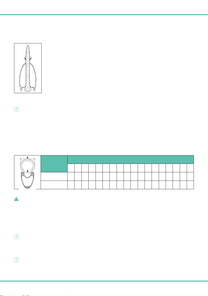
INSTALLING THE TUBELESS VALVE
Remove the lock nut (Fig. 1 - A) that’s screwed onto the exterior valve threads.
Insert the valve into the valve bore on the rim.
Screw the previously removed locknut (fig. 1 - A) back onto the valve, so that the valve is held in place relative to
the rim.
TIRES
CAUTION/IMPORTANT
RIM/TIRE COMPATIBILITY
Reparto Corse rims observe the dimensional requirements defined by ETRTO. Table 3 shows the rim/tire compatibility defined by the
European Tyre and Rim Technical Organization.
If the tire is too easy to fit on the rim, this indicates that the tire may be too big and therefore will not fit properly on the rim.
If it is difficult to mount the tire on the rime, this indicates that the rim may be too small.
Only use high-quality tires that require the use of tire levers.
Mounting the tire should require reasonable effort. Adding talcum powder to the tire will make it easier.
Table 3.
B = RIM WIDTH (mm)
A = TIRE SECTION WIDTH (mm)
23 25 28 30 32 34 36 38 41 43 47 50 52 53 56 60 64 66
21 ••••••••
24 •••••••••••
WARNING/SAFETY RULE
The use of a tire that does not adhere properly to the rim can lead to sudden tire failure, resulting in serious accidents.
TUBELESS READY TIRE COMPATIBILITY CHECK
The wheels are manufactured in accordance with ETRTO dimensional standards.
Tubeless Ready tires are recommended.
CAUTION/IMPORTANT
The functionality of the Tubeless Ready System is dependent on the tires and sealant. There is no warranty for the functionality of this
system. The Manufacturer is therefore held harmless from any liability arising and/or resulting from the functionality of the Tubeless
Ready System and its compatibility with the Wheels.
CAUTION/IMPORTANT
If tubeless ready tires are installed, it is necessary to use anti-puncture sealants.
Danger of rim damage if unsuitable sealant is used.
Never use sealant containing alkaline substances (ammonia, sodium hydroxide).

10
WARNING/SAFETY RULE
Always check the condition of the tire to ensure that the tire isn’t damaged. A damaged tire could suddenly burst.
TUBELESS READY TIRE MOUNTING PROCEDURE
It is recommended to strictly follow the instructions provided by the tubeless tire manufacturer, as well as the following general directions.
11. Make sure the Tubeless Ready tape and the Reparto Corse Tubeless valve are installed.
12. Check the rim and, more specifically, the tire seat for any foreign objects.
13. Follow the tire’s rotational direction.
14. Insert the first of the two tire beads into the rim groove.
15. Insert the second tire bead, starting from the valve bore area.
16. We recommend using soapy water, mounting fluid, or talcum powder to decrease friction between the tire and the rim during mounting.
17. Make sure the valve is fully open.
18. Inflate the tire without exceeding the maximum pressure indicated on the tire by using a compressor so that the tire bead sits on the edge of the rim.
19. Carefully check that the tire beads are evenly seated on the rim all the way around the circumference of the wheel.
20. Deflate the tire by pressing on the top of the valve and prepare tire sealant according to the manufacturer’s instructions.
21. Raise the wheel, holding it upright with the valve at its highest point.
22. If it is possible to insert the sealant with a syringe, remove the valve core using a suitable tool, insert the amount of sealant
recommended by the manufacturer, and reinstall the valve core.
23. If no syringe is available, release the bead on one side of the tire, pour in the sealant, adding the amount recommended by the sealant
manufacturer, and reinstall the bead in the center channel of the rim.
24. Re-inflate the tire without exceeding the maximum pressure indicated on the tire and carefully check that the tire beads are evenly
seated on the rim all the way around the circumference of the wheel.
25. Rotate and shake the wheel so that the sealant can seal the interior surface. Apply soap and water to the tire to check for bubbles,
which indicate an air leak. Position the wheel so that sealant flows into the leak and stops it.
TUBELESS READY TIRE DISMOUNTING PROCEDURE
It is recommended to strictly follow the instructions provided by the tubeless tire manufacturer, as well as the following general directions.
15. Deflate the tire.
16. Beginning on the side opposite the valve, push one side of the tire with your hands until the bead is disengaged from its seat and drops
into the rim groove. Continue around the entire circumference of the wheel.
17. Starting at the valve, pull the tire with your hands until it comes off the rim. Then continue around the entire circumference of the wheel.
18. Do the same on the other side of the tire.
19. Completely remove one side of the tire before proceeding to the other side.
20. Remove the tire.
TIRE MOUNTING PROCEDURE WITH INNER TUBE
1. Before installing the inner tube, make sure that the Manufacturer’s Tubeless Ready sealing tape is not worn or damaged. If this is the
case, you must first replace the sealing tape (see instructions for replacing sealing tape), and only after the sealing tape is replaced
can you proceed with installing the inner tube.
2. Install the inner tube and tire according to the manufacturer’s instructions and the general instructions given in the previous section
“TUBELESS READY TIRE MOUNTING PROCEDURE” steps 2 through 5.
3. After the inner tube and tire are mounted on the Wheel, insert the inner tube valve into the valve bore. Lift and flex the second tire
bead toward the first one for easier insertion without the risk of pinching the inner tube.
4. Insert the valve into the valve bore, and then release the second tire bead by lifting it over the newly inserted inner tube.
5. Mount the inner tube and tire according to the manufacturer’s instructions, or alternatively follow the steps in the previous section
“TUBELESS READY TIRES MOUNTING PROCEDURE” steps 5 through 9.

11
6. Once the tire is inflated to pressure, you can use the anti-vibration adhesive that’s supplied with the Wheel (part number specified in
Tab.1) on the tube valve.
7. Remove the coating from the adhesive.
8. Insert the valve into the adhesive’s center hole and lower the adhesive to the rim along the length of the valve.
9. Fix the adhesive in place, straddling the rim.
10. MOUNTING THE WHEEL ON THE FRAME
Refer to the mounting instructions provided by the bicycle, frame, or fork manufacturer
WARNING/SAFETY RULE
Do not exceed the maximum torque of 20 Nm.
Always check to make sure the wheels are locked securely in place by lifting the bike off the ground and applying downward pressure
to the wheels. The wheels must not move. If the wheels aren’t locked in place, make sure that the locking levers are well-tightened
and repeat the operation.
Errors in wheel installation or adjustment can result in an accident with serious damage and risk of injury.
SPROCKET PACK ASSEMBLY AND DISASSEMBLY
11S, 12S sprockets from SHIMANO (HG-11)
This wheel is also compatible with the SHIMANO HG-11 freewheel body. For installation and maintenance instructions, refer to the instruction
sheet provided by the sprocket pack manufacturer.
11S, 12S sprockets from SRAM CORPORATION (XDR)
This wheel is also compatible with the SRAM XDR freewheel body. For installation and maintenance instructions, refer to the instruction
sheet provided by the sprocket pack manufacturer.
11S, 12S, 13S sprockets from CAMPAGNOLO (N3W)
This wheel is also compatible with the CAMPAGNOLO N3W freewheel body. For installation and maintenance instructions, refer to the
instruction sheet provided by the sprocket pack manufacturer.
BRAKE ROTOR INSTALLATION
Refer to the manufacturer’s instructions for installing the Center Lock brake rotor.
CAUTION/IMPORTANT
It is not recommended to use 6-bolt brake rotors with the Center Lock adapter system.

12
CAUTION/IMPORTANT
VALID ONLY FOR SPBTECH REPARTO CORSE WHEELS
Rear hub is not compatible with Lock ring model type SM-RT81.
SM-RT81 SM-RT30 SM-HB20
SM-RT81 SM-RT30 SM-HB20
SM-RT81 SM-RT30 SM-HB20
SM-RT81 SM-RT30 SM-HB20
CLEANING THE WHEELS
Periodic cleaning of the Wheels should be carried out according to the conditions of the environment, climate, and the types of use to which
they are subjected. For example, using the Wheels in saline environments, such as coastal or seaside areas, require cleaning every time
they are used to prevent corrosion and avoid damage, malfunction, or accidents.
Use only non-aggressive products such as mild soap and water or specific bicycle cleaning products. The use of a soft, non-abrasive
sponge is recommended.
CAUTION/IMPORTANT
DO NOT use solvents, especially alcohol, acetone, gasoline, and diesel fuel, as they may damage the rim decals, which are made out
of material that’s particularly sensitive to solvents.
Rim decals are not replaceable.
NEVER wash the wheels with high-pressure water jets.
TRANSPORT
Proper transport will prevent damage to the Wheels. The following guidelines should be obeyed:
• Do not subject carbon wheels to pressure loads.
• Do not place objects on the Wheels.
• Transport the Wheels using the appropriate Reparto Corse bags;
TRANSPORTING OUTSIDE OF A VEHICLE
When transporting Wheels on a rear bike rack, make sure there is sufficient distance between the car’s exhaust pipe and the Wheels.
CAUTION/IMPORTANT
Transporting the Wheels on a rear bike rack may damage the Wheels due to high exhaust temperatures or impacts caused by external
objects.
Protect the wheel rims with foam-type padding before attaching and tightening the anchor straps.
TRANSPORTING INSIDE A VEHICLE
• When transporting the Wheels inside a vehicle, cover the Wheels to avoid direct sunlight.
• Reduce tire pressure if the vehicle’s interior temperature is elevated.

13
WHEEL STORAGE
Proper and careful wheel storage allows you to be able to use the Product for a long time. The following guidelines should be followed with
respect to this:
• Do not hang Wheels on hooks.
• Reduce tire pressure.
• Periodically clean the Wheels. Completely remove salt residue.
16. WHEEL MAINTENANCE AND INSPECTION
CAUTION/IMPORTANT
Wheel maintenance and inspection should be done at least as often as shown in the table.
Table 4.
Activity Every...
Hub maintenance (refer to service manual):
→ under normal use conditions
→ under severe use conditions (dust/rain/mud)
12 months
3 months
Replace tubeless tape 12 months
Replace tubeless valve 12 months
Check tubeless tape for wear
The tubeless tape should be replaced if there are visible:
→ scratches or scoring due to incorrect use of tire lever
→ severe inward bending of holes on rim top deck
→ bending and misalignment of the tape with respect to the inner rim channel
3 months
Check centring, camber, and tire wear 10 hours of service
Check brake rotor attachment using Center Lock adapter
→ if necessary, check the correct tightening torque of the system
Center Lock using dedicated key
10 hours of service
Make sure the brake rotor and Center Lock adapter are not damaged
→ Otherwise, before using the bike,
replace the disc and Center Lock adapter
Before each use
Check the tire pressure Before each use
Check for obvious damage to the wheel Before and after each use
Check wheel attachment to frame Before and after each use
Cleaning
Use a soft, non-abrasive sponge and a suitable cleaner (see wheel cleaning chapter).
After each use
WARNING/SAFETY RULE
Maintenance and/or inspection of the Wheels performed with less frequency than what is indicated in the table may result in accidents.
17. LEGAL WARRANTY
The Wheels are covered by the legal warranty for any lack of conformity of the Product existing at the time of delivery of the Product and
manifesting itself within two years from that time. In particular, the absence of defects in construction and the quality of the manufacturing
materials are guaranteed. This is subject to the conventionally mandatory provisions of the law in the consumer’s country of residence.
The legal warranty is effective only against the original purchaser and not against any subsequent purchasers who purchased the Product
from the original purchaser.
In order to enforce the legal warranty, the consumer must contact the seller from whom they purchased the Wheels.

14
CAUTION/IMPORTANT
This legal warranty does not apply in the event of neglect, tampering, or misuse of the Product, or in the event of damage caused to the
Product as a result of a fall, or in the event of failure to follow the use and maintenance instructions contained in this manual and/or failure
of the dealer or consumer to follow the assembly instructions.
The legal warranty may not be asserted for slight superficial aesthetic imperfections or in some details of the final finish of the Product as
these are to be considered normal and characteristic of the Product itself. In fact, the craftsmanship of the manufacturing process and the
actions carried out by hand make each Product unique. The craftsmanship of the components may also result in variations in the Product
of ±5% in weight from the nominal value. Such variations are to be considered absolutely normal and therefore cannot be considered
conformity defects.

15
RUOTE REPARTO CORSE
MANUALE D’USO E MANUTENZIONE
COSTRUTTORE/PRODUTTORE
Le ruote Reparto Corse (in seguito “Ruote/a” o “Prodotto”) sono realizzate/prodotte da: F.I.V.E. BIANCHI S.p.A. - Via delle Battaglie, 5 –24047 Treviglio
(BG) - Web: www.bianchi.com (in seguito “Produttore”).
Precisione, performance e stile. Congratulazioni per aver scelto per la tua bici una coppia di ruote di livello superiore. Pronte per l’utilizzo con freni a
disco, grazie al loro profilo aerodinamico sono pronte a farti viaggiare ad alte velocità.
ASPETTI GENERALI
È indispensabile che tutti gli utilizzatori prima dell’uso delle ruote Reparto Corse leggano, comprendano e seguano attentamente le istruzioni
riportate nel presente manuale d’ uso e manutenzione. L’utilizzatore rimane responsabile dei danni arrecati a persone e/o cose e alle Ruote, se esse
sono utilizzate in modo scorretto o non conforme alle istruzioni che seguono.
Questo manuale è parte integrante delle ruote e deve essere conservato per ogni futura consultazione.
RESPONSABILITÀ
Il mancato rispetto delle istruzioni operative e delle prescrizioni di sicurezza contenute nel presente manuale d’uso e manutenzione esime
il Produttore da qualsiasi responsabilità. Il Produttore è altresì manlevato da qualsiasi responsabilità, inclusa ma non limitata alla sicurezza
delle persone, nel caso in cui l’uso e la manutenzione delle Ruote siano eseguite in modo non conforme alle istruzioni fornite e/o le Ruote
siano utilizzate in modo scorretto o tale da pregiudicarne l’integrità e/o modificarne le caratteristiche e/o siano utilizzati ricambi non
originali e/o le stesse non siano assemblate correttamente sulla bicicletta.
COMPETENZE SPECIFICHE
Questo manuale si rivolge all’utilizzatore della Ruota. Include istruzioni riguardanti, la manutenzione e la cura delle Ruote. La maggiore parte delle
operazioni di manutenzione e riparazione delle Ruote richiedono conoscenze specifiche ed attrezzatura adeguata. Qualora l’utilizzatore non possieda
le competenze specifiche richieste e/o l’attrezzatura adeguata, si consiglia di rivolgersi a personale specializzato o ad un rivenditore Bianchi.
LEGENDA
PERICOLO/NORMA DI SICUREZZA
Segnala norme e regole fondamentali ai fini della sicurezza. La non osservanza di tali regole può provocare incidenti, cadute, lesioni
all’utilizzatore e ad altre persone.
AVVERTENZA/ IMPORTANTE
Segnala importanti avvertenze tecniche da seguire rigorosamente ai fini di un corretto utilizzo delle Ruote.
SPECIFICHE TECNICHE
Tab 1.
ANTERIORE POSTERIORE
PERNO Ø12 x 100 mm Ø12 x 142 mm
CORPETTO RUOTA LIBERA
SHIMANO HG-11
SRAM XDR
CAMPAGNOLO N3W
ADESIVO ANTIVIBRANTE VALVOLA Cod. DBU22081 *
VALVOLE H profilo < 45 mm 45 mm < H profilo < 60 mm H profilo > 60 mm
Cod. C4805266 (L=60 mm) * Cod. C4805267 (L=80 mm) * Cod. C4805268 (L=100 mm) *
*I componenti saranno disponibili solo in kit
IT
16
STANDARD DI QUALITA’
Le Ruote sono state controllate secondo lo standard qualitativo del Produttore e testate rispettando la norma di settore UNI EN 4210-7.
DESTINAZIONE DI UTILIZZO DESIGNATA ASTM
AVVERTENZA/ IMPORTANTE
Le Ruote sono state progettate per l’utilizzo esclusivo:
a) su biciclette con freno a disco e sprovviste di motore
b) nelle seguenti categorie: 1 e/o 2 e nella categoria meno gravosa, come definita dalle norme dell’ASTM (American Society for Testing
and Materials) norme che tengono in considerazione le sollecitazioni che le ruote stesse possono affrontare e dei mezzi sui quali
possono essere utilizzate.
(in seguito ci si riferisce congiuntamente ad a) e b) come (“Destinazione di Utilizzo Designata”).
* Categoria ASTM
CATEGORIA 1 ASTM: Percorsi su strade asfaltate. In parole povere, questa categoria include tutte le
biciclette e i componenti, ruote incluse, pensati per l’utilizzo su superfici lisce, e in cui pertanto
entrambi gli pneumatici rimangono a contatto con il terreno.
Elenco ruote Reparto Corse classificate in categoria ASTM1
- RC 65R SPBTECH ETRTO 622 x 21C (Posteriore Cod. C4205982)
- RC 50R SPBTECH ETRTO 622 x 21C (Anteriore Cod. C4105964)
- RC 50R ETRTO 622 x 21C (Anteriore Cod. C4105984 / Posteriore Cod. C4206001)
- RC 33RCERAMITEC ETRTO 622 x 21C (Anteriore Cod. C4105983 / Posteriore Cod. C4206121)
CATEGORIA 2 ASTM: Percorsi asfaltati e fuoristrada con salti inferiori a 15 cm.
A questa tipologia d’uso appartengono le bici e i suoi componenti utilizzabili nella categoria 1 o strade sterrate
(strade bianche). Sia su fondi stradali che su fondi irregolari, la perdita di contatto con il fondo e il conseguente salto
e/o dislivello non deve superare i 15 cm di altezza.
Si raccomanda pertanto l’utilizzo di queste ruote in condizioni di utilizzo per cui sono pensate o per condizioni di
utilizzo meno gravose.
Elenco ruote Reparto Corse classificate in categoria ASTM2
- RC 43CERAMITEC ETRTO 622 x 24C (Anteriore Cod. C4106010 / Posteriore Cod. C4206137)
PERICOLO/NORMA DI SICUREZZA
Qualsiasi utilizzo delle Ruote diverso dalla destinazione di utilizzo designata è proibito.

17
SICUREZZA
PERICOLO/NORMA DI SICUREZZA
Tutte le seguenti indicazioni sono da ritenersi fondamentali per assicurare la sicurezza dell’utilizzatore e di terzi.
1. Il peso massimo consentito: del ciclista, della sua bicicletta e degli eventuali accessori non dovrà superare i 120Kg.
2. Prima di ogni utilizzo verificare il corretto fissaggio della Ruota consultando le istruzioni di montaggio fornite dal costruttore della
bicicletta o della forcella.
3. Prima di ogni utilizzo verificare che la pressione degli pneumatici sia corretta e che non vi sia alcun danno a battistrada e fianchi pneumatico.
4. Prima di ogni utilizzo verificare che non vi sia alcun raggio danneggiato o allentato.
5. Prima di ogni utilizzo verificare la centratura della ruota; verificare che essa non ondeggi radialmente e lateralmente in modo anomalo.
6. Prima di ogni utilizzo verificare il corretto funzionamento dell’impianto frenante.
7. Assicurarsi regolarmente dello stato di usura delle pastiglie dei freni e in caso sostituirle.
8. Assicurarsi che il disco non tocchi le pastiglie freno.
9. La pressione massima di gonfiaggio dello pneumatico, indicata sullo pneumatico stesso non deve essere superata per nessun motivo.
10. La pressione massima di gonfiaggio dello pneumatico tollerata dal cerchio e indicata sul cerchio stesso non deve essere superata per
nessun motivo.
11. La pressione massima di gonfiaggio consentita è quella che risulta essere la minore tra quella specificata sullo pneumatico e quella
specificata sul cerchio.
12. Le Ruote devono essere compatibili con tutte le parti della bicicletta.
13. Le Ruote non devono essere modificate o manomesse.
14. Prima e dopo ogni utilizzo controllare che la ruota non presenti danneggiamenti.
15. Qualora sussistano danneggiamenti o segnali di danneggiamenti, le Ruote non devono essere utilizzate. In caso di dubbi rivolgersi al
proprio rivenditore.
16. Utilizzare solo ricambi originali Reparto Corse (controllare lista compatibilità Tab.1).
FRENI
Utilizzare le Ruote solo su biciclette con impianto frenante a disco.
PERICOLO/NORMA DI SICUREZZA
NON UTILIZZARE LE RUOTE CON IMPIANTI FRENANTI A CERCHIO (CALIPER).
AVVERTENZA/ IMPORTANTE
L’elevata temperatura del disco del freno può causare ustioni.
È importante, per evitare ustioni, fare raffreddare il disco del freno prima di qualsiasi intervento sulla Ruota.
COMPONENTI E ATTREZZI
AVVERTENZA/ IMPORTANTE
La scelta errata di componenti e/o attrezzi può causare un danneggiamento della Ruota.
NON utilizzare leve smonta gomme in metallo. Potrebbero danneggiare la superficie del cerchio, gli pneumatici o anche la camera d’aria.
NASTRO SIGILLANTE TUBELESS READY
PERICOLO/NORMA DI SICUREZZA
Il nastro sigillante Tubeless Ready usurato o danneggiato può causare un’improvvisa perdita di pressione dello pneumatico.
AVVERTENZA/ IMPORTANTE
Controllare il nastro sigillante Tubeless Ready almeno ogni tre mesi per verificarne lo stato di usura.
Controllare il nastro sigillante Tubeless Ready dopo ogni sostituzione dello pneumatico effettuata mediante l’impiego di leve smonta
gomme in resina dura per verificarne le condizioni.
Qualora sussistano danneggiamenti o segnali di danneggiamenti e/o usura, le Ruote non devono essere utilizzate. In caso di dubbi
rivolgersi al proprio rivenditore o a personale specializzato.

18
PROCEDURA DI SOSTITUZIONE NASTRO TUBELESS READY
Si raccomanda di attenersi scrupolosamente alle istruzioni fornite dal produttore dello pneumatico Tubeless ready e alle seguenti
indicazioni generali nel caso in cui sia necessario sostituire il nastro sigillante Tubeless Ready:
1. Rimuovere il nastro precedentemente montato sul cerchio, nel caso si renda necessario utilizzando un attrezzo come cacciavite che
permetta di sollevare e sfilare il nastro senza rovinare il cerchio sottostante.
2. Pulire l’interno del cerchio con panno impregnato di alcool isopropilico, passando letto e pareti dell’interno cerchio.
3. Applicare il nastro tubeless stendendolo in senso antiorario rispetto al lato guarnitura della ruota (lato opposto al disco freno).
4. Il nastro tubeless va teso mentre applicato, come linee guida non deve fare grinze ed aderire al letto del cerchio, rimanendo centrato/
simmetrico rispetto alla larghezza del letto del cerchio.
5. Applicare il primo lembo di nastro tubeless partendo alla metà tra secondo e terzo foro prossimi al foro valvola, proseguire comprendo
il foro valvola e poi proseguire facendo un giro completo fino ad arrivare nuovamente al foro valvola.
6. Dopo aver superato per la seconda volta il foro valvola, tagliare il nastro tubeless quando all’altezza tra secondo e terzo foro.
7. Eseguire un taglio ad “X” per aprire foro valvola sul nastro tubeless tramite taglierino.
8. Prendere come riferimento foro acqua sul lato del cerchio per allineare taglierino al foro valvola coperto dal nastro tubeless.
9. Procedere tagliando ad X con due movimenti distinti, taglierino con punta lama su nastro effettua primo taglio
10. Ruotando il taglierino perpendicolare al taglio precedente effettuare il secondo taglio. Effettuare tagli con attenzione per evitare di
incidere pareti del cerchio.
AVVERTENZA/ IMPORTANTE
Tutta la superficie del nastro deve risultare completamente incollata al letto del cerchio al termine della procedura di montaggio.
Lembi di nastro non devono risultare sollevati o incollati lungo le pareti del letto del cerchio.
Effettuare il taglio del nastro per alloggiamento valvola con attenzione al fine di evitare di incidere pareti del cerchio.
In caso sia necessario sostituire il nastro sigillante, utilizzare il nastro ricambio Reparto Corse, abbinato al prodotto in utilizzo specificato in Tab. 2.
Tab 2.
TIPO RUOTA DIMENSIONE ETRTO CODICE NASTRO
RC 65 SPBTECH ETRTO 622 x 21C C4605132 *
RC 50 SPBTECH ETRTO 622 x 21C C4605132 *
RC 50 ETRTO 622 x 21C C4605132 *
RC 33CERAMITEC ETRTO 622 x 21C C4605132 *
RC 43CERAMITEC ETRTO 622 x 24C C4605136 *
*I componenti saranno disponibili solo in kit
VALVOLA TUBELESS
La valvola tubeless viene fornita dal Produttore. In caso di sostituzione della valvola tubeless, si raccomanda di utilizzare ricambi originali
Reparto Corse (codice ricambio specificato in Tab 1).
AVVERTENZA/ IMPORTANTE
Utilizzare esclusivamente valvole con un diametro adatto e una lunghezza adeguata, come da tabella specifiche tecniche (Tab 1).
Non modificare il foro della valvola.
Controllare periodicamente la tenuta della valvola tubeless e dell’intero sistema.
È consigliata la sostituzione della valvola almeno una volta l’anno.
19
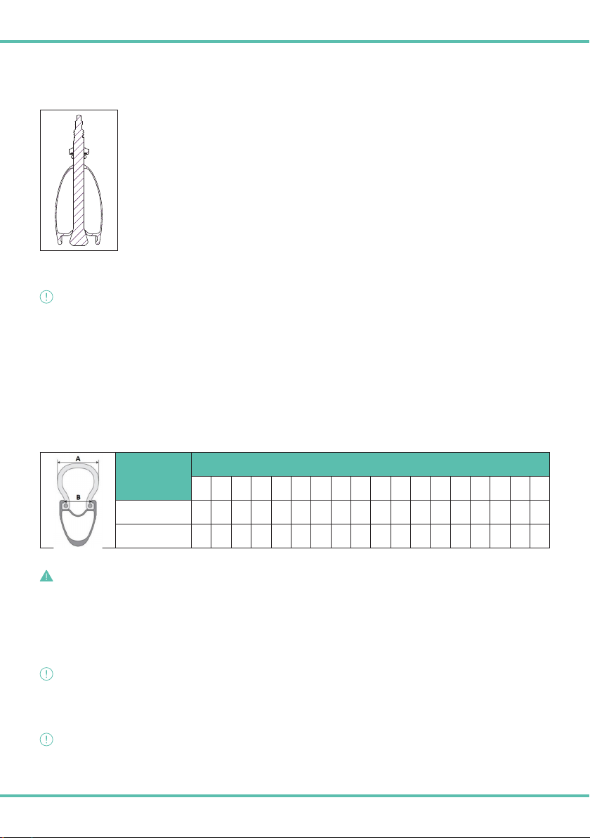
MONTAGGIO DELLA VALVOLA TUBELESS
Svitare dalla valvola il controdado (fig. 1 - A), avvitato lungo la filettatura principale della valvola. Inserire la valvola nel foro valvola sul cerchio.
Avvitare nuovamente sulla valvola il controdado (fig. 1 - A) precedentemente svitato, in modo da fermare in
posizione corretta la valvola rispetto al cerchio.
PNEUMATICI
AVVERTENZA/ IMPORTANTE
COMPATIBILITA’ CERCHIO/PNEUMATICO
I cerchi Reparto Corse seguono le prescrizioni dimensionali definite da ETRTO, la tabella 3 definisce le compatibilità cerchio/
pneumatico definite dall’European Tyre and Rim Technical Organization.
Nel caso in cui il montaggio dello pneumatico su cerchio fosse troppo semplice, lo pneumatico potrebbe essere troppo grande e quindi
non aderire correttamente al cerchio.
Nel caso in cui il montaggio dello pneumatico su cerchio fosse troppo difficile, questo potrebbe essere troppo piccolo.
Usate esclusivamente copertoncini di alta qualità che richiedano l’utilizzo di leve per copertoncini.
Il montaggio del pneumatico deve richiedere uno sforzo ragionevole, l’aggiunta di talco sullo pneumatico agevolerà l’operazione di
installazione dello stesso.
Tab 3.
B = LARGHEZZA DEL
CERCHIO (mm)
A = LARGHEZZA SEZIONE PNEUMATICO (mm)
23 25 28 30 32 34 36 38 41 43 47 50 52 53 56 60 64 66
21 ••••••••
24 •••••••••••
PERICOLO/NORMA DI SICUREZZA
L’uso di uno pneumatico che non aderisce correttamente al cerchio può provocare l’improvvisa rottura dello pneumatico può essere
causa di incidenti gravi.
VERIFICA DELLA COMPATIBILITA’ DELLO PNEUMATICO TUBELESS READY
Le Ruote sono realizzate nel rispetto degli standard dimensionali ETRTO. Si consiglia l’impiego di pneumatici Tubeless Ready.
AVVERTENZA/ IMPORTANTE
La funzionalità del sistema tubeless ready dipende dagli pneumatici e dal liquido sigillante utilizzato, per questo motivo non viene
fornita alcuna garanzia sulla funzionalità di tale sistema. Il Produttore pertanto è manlevato da qualsiasi responsabilità, derivante e/o
conseguente alla funzionalità del sistema tubeless ready e della compatibilità dello stesso con la Ruota.
AVVERTENZA/ IMPORTANTE
Nel caso vengano montati pneumatici tubeless ready devono essere utilizzati idonei sigillanti antiforatura.
Un liquido sigillante non idoneo può comportare il danneggiamento del cerchio.
Non utilizzare mai del liquido sigillante contenente sostanze alcaline (ammoniaca – idrossido di sodio)

20
PERICOLO/NORMA DI SICUREZZA
Controllare sempre lo stato dello pneumatico al fine di verificare che lo stesso non sia danneggiato. Uno pneumatico danneggiato
potrebbe scoppiare improvvisamente.
PROCEDURA DI MONTAGGIO PNEUMATICI TUBELESS READY
Si raccomanda di attenersi scrupolosamente alle istruzioni fornite dal produttore dello pneumatico tubeless ready e alle seguenti
indicazioni generali.
11. Assicurarsi che siano montati il nastro Tubeless Ready e la valvola Tubeless Reparto Corse.
12. Verificare che nel cerchio, e più specificamente nella sede alloggiamento dello pneumatico, non siano presenti corpi estranei.
13. Rispettare il senso di rotazione dello pneumatico.
14. Inserire il primo dei due talloni dello pneumatico nella spalla laterale del cerchio.
15. Montare il secondo tallone dello pneumatico, partendo dalla zona del foro valvola.
16. Consigliamo di utilizzare acqua saponata o liquido di montaggio o talco per diminuire l’attrito tra lo pneumatico e il cerchio in fase di montaggio.
17. Verificare che la valvola sia completamente aperta.
18. Gonfiare lo pneumatico senza superare la pressione massima indicata sullo pneumatico, utilizzando un compressore, in modo che il
tallone dello pneumatico si trovi sul bordo del cerchio.
19. Verificare attentamente che i talloni dello pneumatico siano correttamente posizionati sul cerchio in modo uniforme lungo tutta la
circonferenza della ruota.
20. Sgonfiare lo pneumatico premendo sulla parte superiore della valvola e preparare il liquido sigillante per pneumatici secondo le
istruzioni del produttore.
21. Sollevare la ruota, tenendola in posizione verticale con la valvola nel punto più alto.
22. Se è possibile inserire il liquido con una siringa: rimuovere la parte centrale della valvola utilizzando un attrezzo idoneo, inserire la
quantità di liquido consigliata dal produttore e reinstallare la parte centrale della valvola.
23. Se non si dispone di siringa, sganciare i talloni su un lato dello pneumatico, versare il liquido inserendo la quantità suggerita dal
produttore del liquido e riposizionare il tallone nel canale centrale del cerchio.
24. Rigonfiare lo pneumatico senza superare la pressione massima indicata sullo pneumatico e controllare attentamente che i talloni
dello pneumatico siano correttamente posizionati sul cerchio in modo uniforme lungo tutta la circonferenza della ruota.
25. Ruotare e scuotere la ruota in modo che il liquido possa sigillare tutta la sua superficie interna. Applicare acqua e sapone su zona
accoppiamento cerchio pneumatico e verificare la presenza di eventuali bolle, che indicherebbero perdite d’aria. Posizionare la ruota
in modo che il liquido fluisca nell’area della perdita d’aria, in modo che il liquido possa bloccarla.
PROCEDURA DI SMONTAGGIO PNEUMATICI TUBELESS READY
Si raccomanda di attenersi scrupolosamente alle istruzioni fornite dal produttore dello pneumatico tubeless ready e alle seguenti indicazioni generali.
15. Sgonfiare lo pneumatico
16. Iniziare dal lato opposto alla valvola, spingere con le mani un lato dello pneumatico fino a sganciare il tallone dalla sua sede, farlo
scendere nella gola del cerchio. Proseguire per tutta la circonferenza della ruota.
17. Partire dalla zona valvola, tirare lo pneumatico con le mani, fino a farlo uscire dal cerchio. Proseguire poi per tutta la circonferenza della ruota.
18. Fare le stesse operazioni anche sull’altro lato dello pneumatico.
19. Smontare completamente un lato dello pneumatico prima di procedere con l’altro lato
20. Rimuovere lo pneumatico.
PROCEDURA MONTAGGIO PNEUMATICI CON CAMERA D’ARIA
1. Prima dell’assemblaggio della camera d’aria assicurarsi che il nastro sigillante Tubeless Ready del Produttore, montato di serie non
sia usurato o danneggiato. In tal caso occorre prima effettuare l’operazione di sostituzione del nastro sigillante (si veda istruzione
operativa di sostituzione nastro) e solamente ad operazione conclusa si potrà procedere con l’assemblaggio della camera d’aria.
2. Montare la camera d’aria e lo pneumatico in base alle indicazioni del costruttore e le indicazioni generali indicate alla precedente
sezione “PROCEDURA DI MONTAGGIO PNEUMATICI TUBELESS READY” punti dal 2 e 5.
3. Successivamente al montaggio della camera d’aria e dello pneumatico sulla Ruota, inserire la valvola della camera d’aria nel foro
Table of contents
Languages:
Other Bianchi Bicycle Accessories manuals


