Bianchi SPECIALISSIMA RC Configuration guide

C8005092-001 | 12 June 2023
USER MANUAL SUPPLEMENT
SPECIALISSIMA RC, PRO, COMP

2

3
INDEX
ENGLISH
ITALIANO
DEUTSCH
FRANÇAIS
ESPAÑOL
日本語
4
10
16
22
28
34

4
DECLARATION OF CONFORMITY
The manufacturer F.I.V.E. Bianchi S.p.A. located at Via delle Battaglie, 5 - 24047 Treviglio (BG), Italy, hereby declares that its products
conform with standard ISO4210. The products also conform with the provisions of Art. 50 of the Italian Highway Code (Italian Legislative
Decree no. 285 of 30 April 1992, as amended, and as amended by Art. 24/1 of Law no. 14 of 3 February 2003), as defined by Art. 2,
paragraph 1, letter n) of the Agreement.
The complete list of product codes and the relative compliance information can be consulted under the “Declaration of Conformity” link
at https://www.bianchi.com/manuals/.
GENERAL SAFETY WARNINGS
Please pay close attention to the following symbols.
DANGER!
indicates a potential danger which may cause serious injury or death if not avoided.
WARNING!
indicates practices and conduct to be adopted for safe product use.
INFORMATION!
Indicates additional information on how to use the product.
WARNING!
Please note that failure to comply with the warnings and provisions contained in this data sheet exempts the manufacturer of
any liability.
INTENDED USE
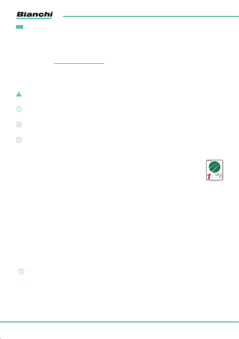
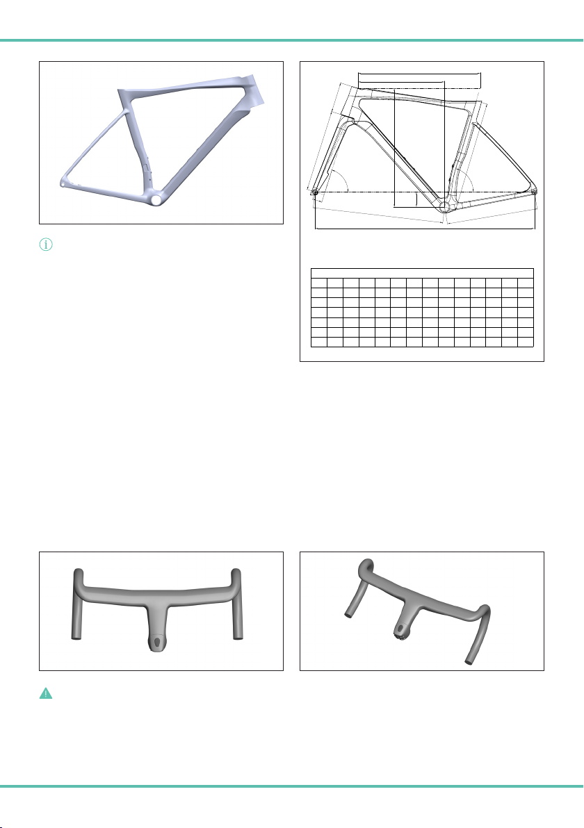
ASTM CATEGORY 1
Designed for use on paved surfaces such as asphalt roads and cycleways.
The tyres remain in constant contact with the ground.
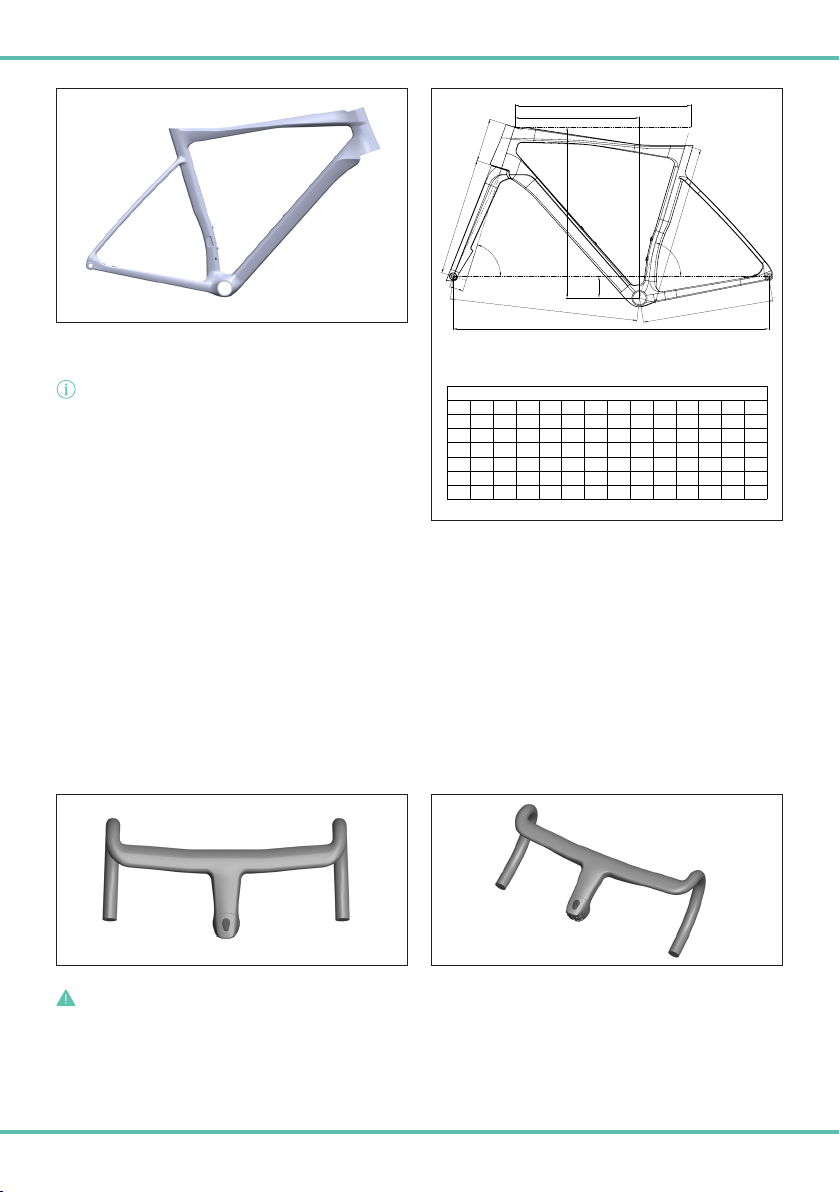
FRAME AND FORK
The frame and fork of the RC, PRO and COMP models are 100% carbon fibre and designed to the specifications of Bianchi engineers to
optimise the sports performance and aesthetics, rigidity and lightness of the Specialissima frame.
Internal cable housing and casing.
Standard Press-Fit 86.5 x 41mm bottom bracket.
The head tube is designed to house two 1”1/2 bearings.
The frame and fork are equipped with M12 thru-axles to attach the wheels.
The frame is compatible with electronic shifting systems only.
Maximum tyre width 32mm. *
The frame is compatible with bottle cages mounted to the seat post and the down tube.
The frame is compatible with brazed-on derailleurs only.
The RC frame weighs 780g ± 5% (medium, 55).
The PRO frame weighs 830g ± 5% (medium, 55). * equipped with Bianchi CV system technology
The COMP frame weighs 900g ± 5% (medium, 55).
The Specialissima RC, PRO and COMP frames conform to UCI regulations.
* WARNING!
The measurement refers to the actual size and not to the image on the cover.
EN
5
SPECIALISSIMA RC AND PRO INTEGRATED HANDLEBAR
The integrated handlebar is a component designed specifically for frames in the Specialissima range to offer optimum integration
between frame, head set and handlebar.
The Specialissima frame uses the ICR head set system manufactured by Acros to route the cables within the handlebar and frame. The
handlebar is designed to integrate seamlessly with the head set.
Handlebar assembly, maintenance and disassembly must be carried out by a specialist retailer ONLY.
NEVER carry out work on the handlebar. These operations require specific technical knowledge, tools and expertise and should ONLY be
carried out by a specialist retailer.
Adjusting the height of the handlebar to suit personal requirements requires expertise, appropriate tools and practical ability. As such,
all adjustments should be carried out by a specialist retailer.
The handlebar stem is attached to the fork by two screws located on the side of the handlebar and by a tapered nut; the screws are
M5x22 mm in length. The torque of the screws is 5-6 Nm.
INFORMATION!
New and innovative components and features are being
developed all the time.
To check compatibility with drive units other than those
originally installed on the Bianchi frame or to receive
information and instructions on specific components that
may be required to install a product or to upgrade one, please
contact a specialist Bianchi retailer.
A
B1
C
D
E
F
G
G1
H
I
X
Y
WB
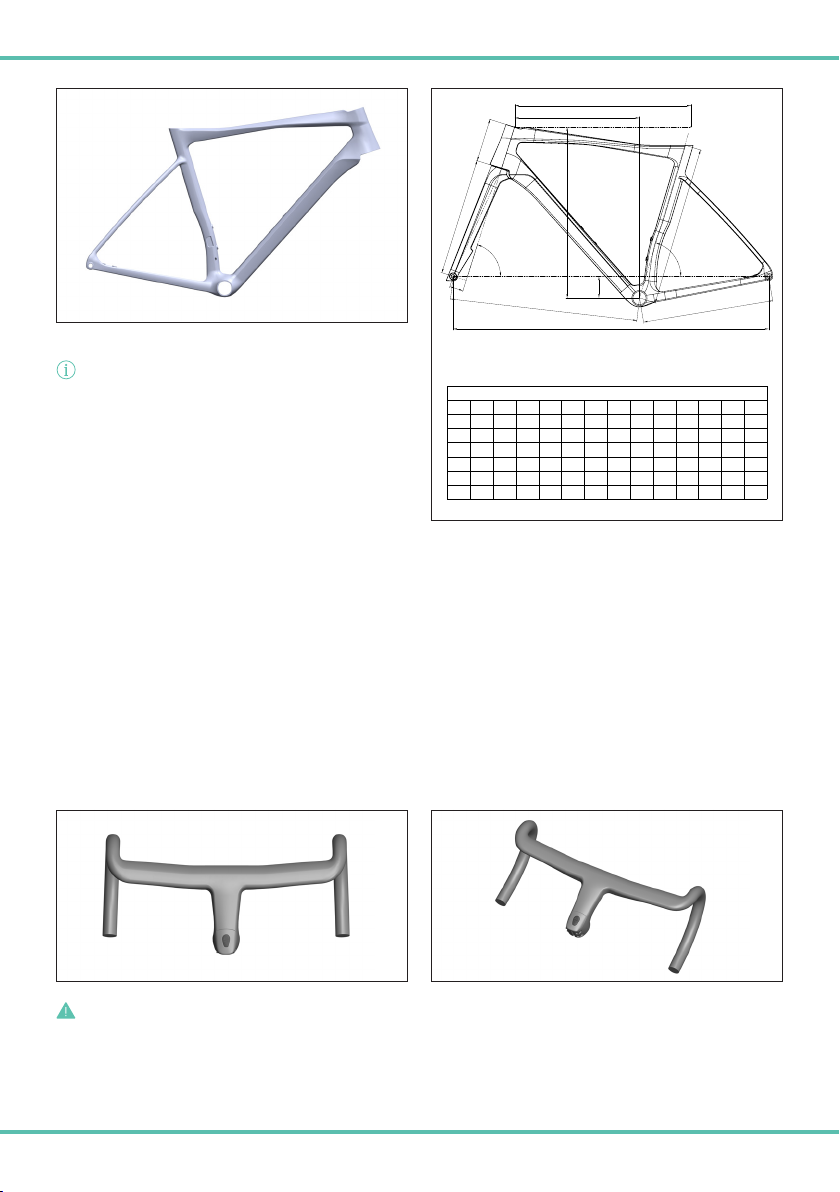
Specialissima (all)
SIZE AB1 CD E F GG1 H I X Y WB
470 420 514 410 58 100 579 74.5° 70.5° 43 368 379 486 982
500 450 524 410 58 105 581 74.5° 71.5° 43 368 386 494 983
530 480 535 410 68 120 582 74° 72° 43 368 387 520 984
550 500 550 410 68 135 588 73.5° 72.5° 43 368 391 536 988
570 520 560 412 68 150 593 73.5° 73° 43 368 397 552 996
590 540 575 412 68 170 603 73° 73° 43 368 400 571 1005
DANGER!
Always comply with the torque values specified on the stem. Incorrect tightening may cause the component to malfunction or
break, causing the rider to lose control and fall.
Never use this product with incomplete or incorrect assembly. This endangers not only the rider but also other road users.
6
WARNING!
Turn the handlebar left and right. Do not use the bike if there is any evidence of abnormal steering (play in the steering or uneven
resistance) or if any cracks or signs of damage are evident.
In the event of an accident or fall, the handlebar will almost certainly be involved and will be subjected to high levels of stress and impact.
In the event of any deep scratches or cracks, replace the components.
WARNING!!
If the handlebar is damaged, stop using the Specialissima RC and/or PRO bike
immediately. Do not use the Specialissima RC and/or PRO bike until a specialist
retailer has conducted a full inspection and, if necessary, the handlebar has been
replaced.
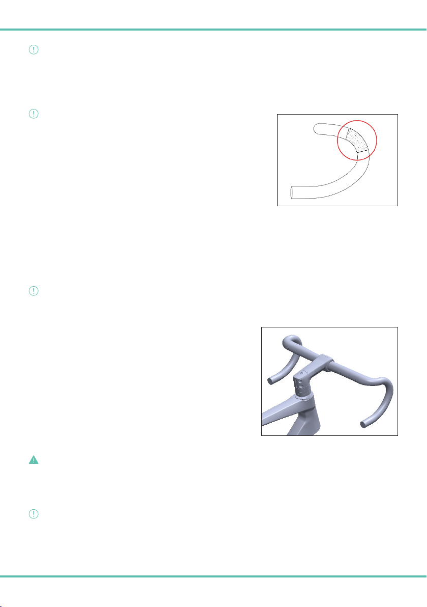
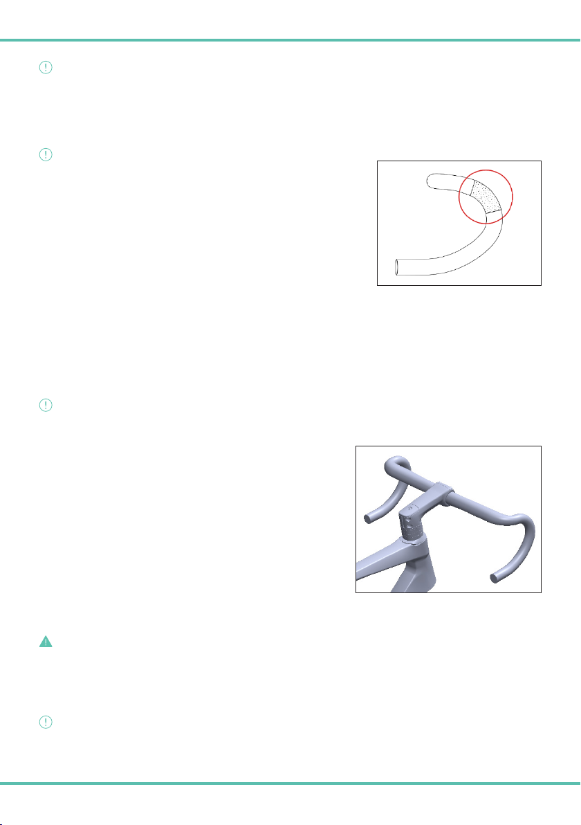
The gear/brake control levers are mounted on the handlebar using a clamp integrated
into the lever.
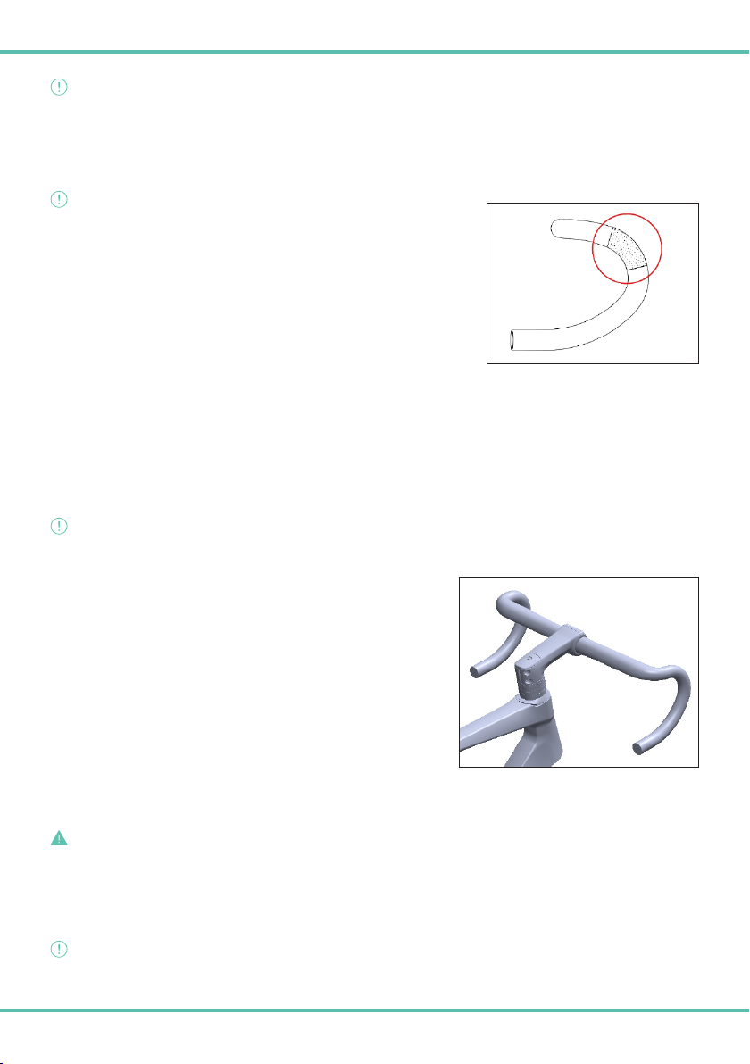
Pay close attention to the recommended positioning of the levers and respect the limits
indicated by the high grip zone (image 1A).
Consult the lever product handbook for the correct torque. To preserve the integrity of
the handlebar bend, do not exceed the maximum torque of 10 Nm.
BIKE COMPUTER MOUNT FOR SPECIALISSIMA RC AND PRO INTEGRATED HANDLEBAR
The integrated handlebar provided with the Specialissima RC and PRO models is compatible with bike computer mounts
that are attached to the handlebar using two M5 screws.
Tighten the screws to the recommended torque of 2/3 Nm, as indicated on the handlebar.
Always use the safety strap supplied with the bike computer to fasten it to the handlebar.
WARNING!!
Check that the mount is installed correctly before using the bike computer.
SPECIALISSIMA COMP HANDLEBAR STEM AND BEND
The handlebar kit provided with the Specialissima Comp frame is composed
of a stem and bend designed specifically for this frame and uses Velomann
components.
The Specialissima Comp frame uses the ICR head set system manufactured
by Acros to route the cables within the handlebar and frame. The handlebar is
designed to integrate seamlessly with the head set.
During assembly, the cables enter the handlebar bend near the levers and exit
under the stem, and then enter the frame through the spacers and head set.
The height of this type of handlebar stem is adjustable by a specialist retailer.
Due to the importance and complexity of this component, please consult your
retailer for stem adjustment and to fully understand the mechanisms and
adjustment methods.
DANGER!
Always comply with the torque values specified on the stem. Incorrect tightening may cause the component to malfunction or
break, causing the rider to lose control and fall.
Never use this product with incomplete or incorrect assembly. This endangers not only the rider but also other road users.
WARNING!!
Turn the handlebar left and right. Do not use the bike if there is any evidence of abnormal steering (play in the steering or uneven
resistance) or if any cracks or signs of damage are evident.
image 1A

7
In the event of an accident or fall, the handlebar will almost certainly be involved and
will be subjected to high levels of stress and impact. In the event of any deep scratches
or cracks, replace the components.
WARNING!!
If the handlebar is damaged, stop using the Specialissima Comp bike immediately.
Do not use the Specialissima Comp bike until a specialist retailer has conducted a
full inspection and, if necessary, the handlebar has been replaced.
The gear/brake control levers are mounted on the handlebar using a clamp integrated
into the lever.
Pay close attention to the recommended positioning of the levers and respect the
positioning of the high grip zone (image 1A). Consult the lever product handbook for
the correct torque. To preserve the integrity of the handlebar bend, do not exceed the
maximum torque of 10 Nm.
THRU-AXLE
WARNING!!
Use caution and observe the following warnings.
Unlike quick-release systems, the thru-axles provided with this model are screwed directly onto the frame and fork dropouts using an M12
screw. Comply with the torques indicated on the thru-axles.
Female threads are housed in the frame and fork; the thru-axle with the male thread has a specific length to enable safe assembly of the
wheels. (images 1B and 1C)
The use of a thru-axle other than the one provided may result in the incorrect assembly of the wheel and may compromise the integrity
of the frame and fork.
image 1A
WARNING!!
Always use the thru-axles provided with the model. The use of thru-axles other than those specified may cause the frame and/or
fork to break.
DANGER!
Incorrectly mounted wheels may result in falls and serious accidents. If in doubt, contact your specialist retailer.
DANGER!
Always comply with the torque levels specified on the thru-axles. Never exceed the maximum torque value indicated. Incorrect
tightening may damage the frame and fork.
Image 1CImage 1B
8
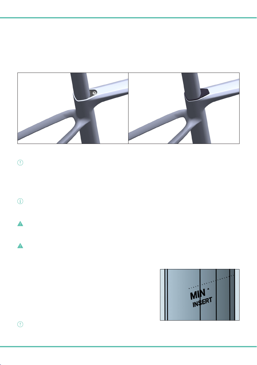
SEAT POST CLAMP/EXPANDER
The seat post clamp/expander provided is designed specifically for use with the Specialissima RC, PRO and COMP frames. Without this
component, it is not possible to lock the seat post in the desired position. (image 1D).
Pay close attention to the warnings given below. Failure to comply with the warnings and provisions contained in this data sheet exempts
the manufacturer from any liability.
To change the saddle height, lift the rubber cover on the frame to access the M5 screw on the clamp/expander; loosen this M5 screw and
adjust the height of the seat post.
Image 1D
WARNING!!
Do not extract, move or adjust the seat post (e.g., to adjust the saddle height) without having loosened the screws on the clamp/
expander!
Once the saddle is adjusted to the desired height, tighten the M5 screws and respect the recommended torque value of the clamp/
expander (6 Nm). Next, reposition the rubber cover in its original position.
INFORMATION!
For optimum grip and to eliminate slippage between the seat post and the frame, place a layer of gripper paste on the part of the
expander that is in contact with the seat post. (the gripper paste is included with the product).
DANGER!
The clamp is equipped with M5x35 mm screws; please only use the specified screw. Using a different screw can compromise the
tightness of the seat post clamp/expander and cause the seat post to drop suddenly, resulting in possible falls.
DANGER!
Always comply with the torque levels specified on the seat post clamp/expander. Failure to comply with the recommended torque
levels may lead to malfunction and cause the rider to fall.
SEAT POST
The carbon fibre D Shape seat post is specifically designed for the Specialissima
RC, PRO and COMP frame to ensure optimum integration between seat post and
frame. Each frame size is supplied with a seat post of the correct length and design
to protect the integrity of the frame.
Always observe the maximum and minimum insertion limits.
280 mm seat post > 47 cm frame
300 mm seat post > 50 cm / 53 cm frame
350 mm seat post > 55 cm / 57 cm / 59 cm frame
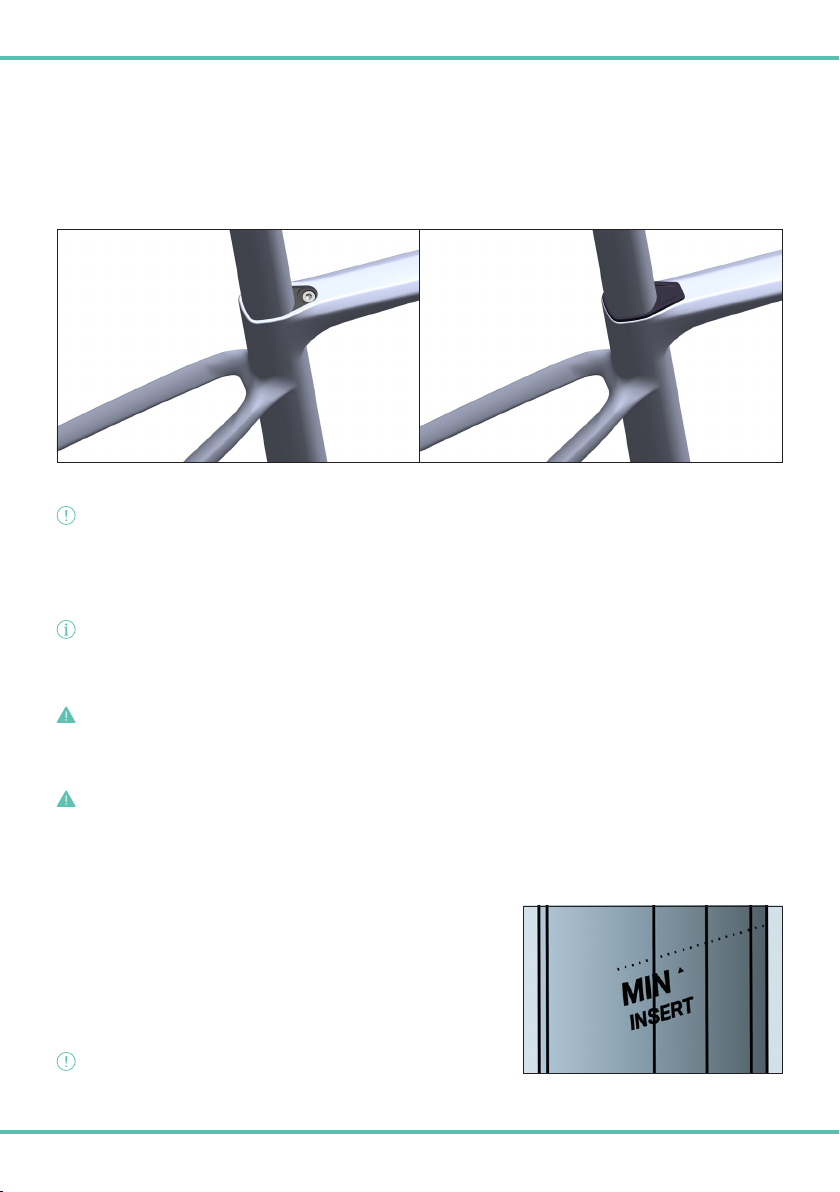
WARNING!!
When removing the seat post never exceed the safety limit indicated on the
component. (image 1E)
Image 1E
9
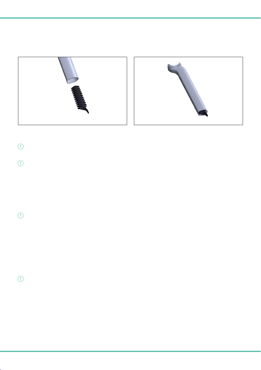
ELECTRONIC SHIFTER BATTERY
If using the Shimano Di2 electronic shifting system, the battery is integrated into the seat post using a specific rubber interlocking
system (Image 1F and 1G). Always take care when removing the seat post to avoid damaging the battery or the transmission system
cables.
Image 1GImage 1F
WARNING!!
Be careful to avoid damaging the cables when extracting the seat post from the frame as the cables may be too short to allow this.
WARNING!!
Check that the battery is securely attached inside the seat tube. Incorrect assembly may cause the battery to fall and become
damaged.
HOW TO USE STABILISERS
Bianchi bike frames are almost always compatible with stabilisers.
Stabilisers must be positioned on the frame at the attachment points of the rear wheel hub only. All adjustments made to the bike are
at the owner’s own risk. Bianchi does not provide any guarantee or assume any responsibility in the case of product damage.
WARNING!!
Before purchasing or using stabilisers, always check that the bike and the stabilisers are fully compatible. Bianchi does not provide
any guarantee or assume any responsibility in the case of product damage.
ADDITIONAL TECHNICAL INFORMATION
Not all components available on the market are compatible with the Specialissima frame.
Not all devices available on the market, such as child seats, stabilisers and bike cargo trailers, are compatible with the Specialissima
frame.
Only the components specified on the product have been tested by Bianchi. Please check design and compatibility before purchasing
new components and devices.
WARNING!!
Before purchasing and assembling products and/or devices, always check that the bike and the components are fully compatible.
Bianchi does not provide any guarantee or assume any responsibility in the case of product damage.
10
DICHIARAZIONE DI CONFORMITÀ
Il produttore F.I.V.E. Bianchi S.p.A. sito in Via delle Battaglie, 5 - 24047 Treviglio (BG), dichiara che i suoi prodotti sono conformi alle corrispondenti
normativa ISO4210. I prodotti rispondono inoltre a quanto disposto dall’art. 50 del Codice della strada (decreto legislativo 30 aprile 1992 n. 285
e successive modificazioni, così come innovato dall’art. 24/1 della legge 3 febbraio 2003 n. 14) così come definiti all’art. 2, comma 1, lettera n
dell’Accordo.
Al seguente indirizzo web https://www.bianchi.com/manuals/ alla voce dichiarazione di conformità è possibile consultare l’elenco completo dei
codici prodotto e le relative compatibilità.
AVVERTENZE DI SICUREZZA GENERALI
Prestare particolare attenzione ai seguenti simboli.
PERICOLO!
segnala un possibile pericolo, che se non evitato può comportare la morte o gravi lesioni.
ATTENZIONE!
segnala norme e comportamenti da apprendere per conoscere e utilizzare il prodotto in sicurezza.
INFORMAZIONE/NOTA!
segnala informazioni aggiuntive utili all’uso del prodotto.
ATTENZIONE!
Si precisa che il mancato rispetto delle avvertenze e delle prescrizioni contenute nel presente foglietto illustrativo esime il produttore
da qualsiasi responsabilità.
DESTINAZIONE D’USO
ASTM CATEGORIA 1
Destinate ad essere utilizzate su superfici pavimentate artificialmente quali strade asfaltate e piste ciclabili.
Le ruote sono costantemente a contatto con il suolo.
TELAIO E FORCELLA
Telaio e forcella RC, PRO e COMP sono realizzati interamente in fibra di carbonio, disegnati e progettati secondo le specifiche dei tecnici Bianchi,
per conferire massima sportività, rigidezza e leggerezza al telaio Specialissima.
L’alloggiamento dei cavi e guaine è completamente interno al telaio.
La scatola movimento centrale adotta lo standard Press-Fit 86,5x41mm.
Il tubo sterzo è realizzato per alloggiare cuscinetti entrambi da 1”1/2.
Telaio e forcella adottano perni passanti da M12 per il fissaggio ruote.
Il telaio è compatibile unicamente con trasmissioni di tipo elettronico.
La sezione massima assemblabile degli pneumatici è 32mm. *
Il telaio è predisposto per l’assemblaggio di porta borraccia al tubo sella e al tubo obliquo.
Il telaio è compatibile solo con deragliatori di tipologia a saldare, senza fascetta (brazed-on).
Il peso del telaio RC nella misura media (55) è 780 gr ± 5%.
Il peso del telaio PRO nella misura media (55) è 830 gr ± 5%. * dotato di Bianchi CV system technology
Il peso del telaio COMP nella misura media (55) è 900 gr ± 5%.
I telai Specialissima RC, PRO e COMP sono omologati secondo le norme UCI.
* ATTENZIONE!
La misura si riferisce ad una dimensione reale e non a quanto indicato sulla copertura.
IT
11
MANUBRIO INTEGRATO SPECIALISSIMA RC E PRO
Il manubrio integrato è un componente realizzato per i telai della serie Specialissima, disegnato per una perfetta integrazione tra telaio, serio
sterzo e manubrio.
Il telaio Specialissima utilizza il sistema serie sterzo ICR di Acros per per l’integrazione totale dei cavi all’interno del manubrio e del telaio. Il
manubrio ha un design che permette una perfetta integrazione con la serie sterzo.
Gli interventi di assemblaggio, manutenzione o smontaggio del manubrio, eventualmente necessari, devono essere eseguiti SOLO dal rivenditore
specializzato.
NON eseguire mai interventi sul manubrio. Tali interventi richiedono conoscenze tecniche specifiche, attrezzi speciali e competenze ben precise
e possono essere svolti SOLO dal rivenditore specializzato.
Regolare l’altezza manubrio in base alle proprie esigenze richiede esperienza, attrezzi adatti e abilità manuale. Pertanto, è opportuno lasciare che
tutti i lavori di regolazione vengano realizzati dal rivenditore specializzato.
L’attacco manubrio si blocca alla forcella tramite due viti poste lateralmente al manubrio e da un dado di forma rastremata; la viteria ha lunghezza
di M5x22 mm. La coppia di chiusura delle viti è 5-6 Nm.
INFORMAZIONE/NOTA!
Sempre più frequentemente componenti e caratteristiche
totalmente nuove e innovative vengono ideate.
Per conoscere la compatibilità con le linee di componenti-
trasmissioni (drive-unit) diverse dsa quelle assemblate in origine
sul telaio Bianchi o per ricevere informazioni e indicazioni di
eventuali componenti specifici necessari per il montaggio del
prodotto o per il suo upgrade, si prega di contattare il rivenditore
specializzato Bianchi.
A
B1
C
D
E
F
G
G1
H
I
X
Y
WB
Specialissima (all)
SIZE AB1 CD E F GG1 H I X Y WB
470 420 514 410 58 100 579 74.5° 70.5° 43 368 379 486 982
500 450 524 410 58 105 581 74.5° 71.5° 43 368 386 494 983
530 480 535 410 68 120 582 74° 72° 43 368 387 520 984
550 500 550 410 68 135 588 73.5° 72.5° 43 368 391 536 988
570 520 560 412 68 150 593 73.5° 73° 43 368 397 552 996
590 540 575 412 68 170 603 73° 73° 43 368 400 571 1005
PERICOLO!
Attenersi alle coppie di serraggio specificate sull’attacco manubrio. Serraggi non correttamente eseguiti possono causare il
malfunzionamento o la rottura del componente con conseguente perdita del controllo del veicolo e cadute!
Non utilizzare mai il prodotto qualora i lavori di assemblaggio siano incompleti o svolti in modo scorretto. In questo modo, infatti, si mette in
pericolo se stessi e gli altri mezzi di circolazione.
12
ATTENZIONE!
Ruotare il manubrio verso sinistra e verso destra, non utilizzare la bicicletta se si nota un comportamento anomalo dello sterzo (gioco nello
sterzo o resistenza non uniforme) o se sono evidenti delle cricche e crepe.
In caso di caduta accidentale o incidente il manubrio sarà quasi certamente coinvolto. Verrà sottoposto a forte sollecitazione e impatti. La
presenza di graffi profondi e incrinature indica che le parti devono essere sostituite.
ATTENZIONE!
Qualora il manubrio risulti danneggiato l’utilizzo della bicicletta Specialissima RC e/o
PRO dovrà essere interrotto immediatamente. Tornare ad utilizzare la Specialissima
RC e/o PRO solo dopo che il rivenditore specializzato l’avrà sottoposta ad accurata
ispezione e, nel caso, sostituito il manubrio se danneggiato.
Le leve comando cambio/freno si fissano alla piega manubrio mediante fascetta integrata
alla leva comando.
Prestare molta attenzione al corretto posizionamento delle leve, rispettare la posizione di
fissaggio entro i limiti indicati dalla zona ad alto grip (immagine 1A).
Consultare lo specifico manuale del produttore delle leve comando cambio/freno per
conoscere la coppia di serraggio da applicare. Per preservare l’integrità della piega manubrio
non superare la coppia massima di 10 Nm.
SUPPORTO CICLO COMPUTER PER MANUBRIO INTEGRATO DI SPECIALISSIMA RC E PRO
Il manubrio integrato in dotazione a Specialissima RC e PRO è predisposto al montaggio di supporti per ciclo computer.
È compatibile con i supporti ciclo computer che si fissano alla piega manubrio tramite due viti M5.
Serrate le viti con una coppia di serraggio consigliata di 2/3Nm, come riportato sul manubrio.
Si ricorda di utilizzare il laccetto di sicurezza fornito in dotazione al ciclo computer (legare il ciclo computer al manubrio).
ATTENZIONE!
Verificare che il supporto sia installato correttamente prima di utilizzare il ciclo computer.
ATTACCO E PIEGA MANUBRIO SPECIALISSIMA COMP
Il kit manubrio in dotazione al telaio Specialissima Comp è composto da un attacco e
da una piega manubrio appositamente disegnati per questo telaio, i componenti sono
marchiati Velomann.
Il telaio Specialissima Comp utilizza il sistema serie sterzo ICR di Acros per
l’integrazione totale dei cavi all’interno del manubrio e del telaio. Il manubrio ha un
design che permette una perfetta integrazione con la serie sterzo.
Nel montaggio i cavi entreranno nella piega manubrio in prossimità delle leve ed
usciranno sotto l’attacco manubrio, dopodiché entreranno nel telaio passando
attraverso gli spessori (spacers) e la serie sterzo.
La regolazione in altezza di questa tipologia di attacco manubrio può essere
eseguita, in origine, dal rivenditore specializzato. In considerazione della rilevanza e
complessità di questa specifica componentistica, invitiamo sempre a consultare il
rivenditore di fiducia per la regolazione dell’attacco manubrio e per comprendere a fondo i meccanismi e le metodologie di regolazione.
PERICOLO!
Attenersi alle coppie di serraggio specificate sull’attacco manubrio. Serraggi non correttamente eseguiti possono causare il
malfunzionamento o la rottura del componente con conseguente perdita del controllo del veicolo e cadute!
Non utilizzare mai il prodotto qualora i lavori di assemblaggio siano incompleti o svolti in modo scorretto. In questo modo, infatti, si mette in
pericolo se stessi e gli altri mezzi di circolazione.
ATTENZIONE!
Ruotare il manubrio verso sinistra e verso destra, non utilizzare la bicicletta se si nota un comportamento anomalo dello sterzo (gioco nello
sterzo o resistenza non uniforme) o se sono evidenti delle cricche e crepe.
immagine 1A

13
In caso di caduta o incidente il manubrio sarà quasi certamente coinvolto. Verrà sottoposto
a forte sollecitazione e impatti. La presenza di graffi profondi e incrinature indica che le parti
devono essere sostituite.
ATTENZIONE!
Qualora il manubrio risulti danneggiato l’utilizzo della bicicletta Specialissima Comp
dovrà essere interrotto immediatamente. Tornare ad utilizzare la Specialissima Comp
solo dopo che il rivenditore specializzato l’avrà sottoposta ad accurata ispezione e, nel
caso, sostituito il manubrio se danneggiato.
Le leve comando cambio/freno si fissano alla piega manubrio mediante fascetta integrata
alla leva comando.
Prestare molta attenzione al corretto posizionamento delle leve, rispettare la posizione di
fissaggio, zona ad alto grip (immagine 1A). Consultare lo specifico manuale del produttore
delle leve comando cambio/freno per conoscere la coppia di serraggio da applicare. Per
preservare l’integrità della piega manubrio non superare la coppia massima di 10 Nm.
PERNI PASSANTI “THRU-AXLE”
ATTENZIONE!
Si prega di fare molta attenzione e di rispettare le avvertenze che seguono.
I perni passanti forniti in dotazione, diversamente dai bloccaggi rapidi “quick release”, si avvitano direttamente sui forcellini del telaio e della
forcella, attraverso una filettatura M12. Attenersi alle coppie di chiusura indicate sui perni.
Nel telaio e nella forcella sono alloggiati i filetti femmina, ne consegue che il perno “thru-axle” con filetto maschio ha una lunghezza specifica per
poter assemblare le ruote in sicurezza. (immagini 1B e 1C)
L’utilizzo di un perno diverso, da quello in dotazione, può implicare un assemblaggio scorretto della ruota e compromettere l’integrità del telaio
e forcella.
immagine 1A
immagine 1Cimmagine 1B
ATTENZIONE!
Attenersi al rispetto e all’utilizzo dei perni passanti che trovate in dotazione al prodotto. L’utilizzo di perni passanti differenti da quelli
specificati può provocare la rottura del telaio e/o forcella.
PERICOLO!
Le ruote montate scorrettamente possono causare cadute e gravi incidenti. In caso di dubbi contattare il proprio rivenditore specializzato
PERICOLO!
Attenersi alla coppia di serraggio specificata sui perni passanti. Non superare mai la coppia massima di serraggio indicata. Serraggi non
correttamente eseguiti possono danneggiare il telaio e la forcella.

14
BLOCCHETTO CHIUSURA REGGISELLA/EXPANDER
Il blocchetto di chiusura/expander in dotazione è un componente specifico per il telaio Specialissima RC, PRO e COMP. Senza di esso non è
possibile bloccare il cannotto reggisella nella posizione desiderata. (immagine 1D).
Seguire attentamente le avvertenze sotto riportate. Il mancato rispetto delle avvertenze e delle prescrizioni contenute nel presente foglietto
illustrativo esime il produttore da qualsiasi responsabilità.
Per cambiare l’altezza sella è necessario sollevare la cover in gomma presente sul telaio per raggiungere la vite M5 del blocchetto di chisura/
expander; allentare tale vite M5 e procedere alla regolazione in altezza del cannotto sella.
immagine 1D
ATTENZIONE!
Non estrarre, muovere o regolare il cannotto reggisella (ad esempio per regolare l’altezza della sella) senza avere allentato la vite di
serraggio del blocchetto di chiusura/expander!
Una volta impostata l’altezza sella desiderata serrare la vite M5 rispettando la coppia di chiusura raccomandata del blocchetto di chiusura/
expander di 6Nm. In seguito, riabbassare la cover in gomma nella posizione iniziale.
INFORMAZIONE/NOTA!
Per garantire un maggiore grip ed un migliore fissaggio del tubo reggisella nel telaio, si consiglia di porre un velo di pasta grippante sulla
parte dell’espander a contatto con il reggisella. (la pasta grippante è in dotazione al prodotto).
PERICOLO!
Il blocchetto di chiusura è dotato di vite M5x35 mm, attenersi all’uso unicamente della vite specificata. L’utilizzo di una vite diversa può
compromettere la tenuta stessa del blocchetto di chiusura reggisella/expander con conseguente abbassamento improvviso del cannotto
reggisella e possibili cadute.
PERICOLO!
Attenersi alla coppia di serraggio specificata sul blocchetto chiusura/expander. Serraggi non correttamente eseguiti possono causare il
malfunzionamento del componente e di conseguenza cadute!
CANNOTTO REGGISELLA
Il cannotto reggisella in dotazione è un componente in carbonio e specifico del telaio
Specialissima RC, PRO e COMP per la perfetta integrazione, e denominato D shape.
Ogni taglia di telaio è fornita con un cannotto reggisella della lunghezza corretta ed
opportuna per la salvaguardia del telaio.
Rispettare le regole minime e massime di inserimento.
Cannotto reggisella 280 mm > telaio misura 47 cm
Cannotto reggisella 300 mm > telaio misura 50 cm / 53 cm
Cannotto reggisella 350 mm > telaio misura 55 cm / 57 cm / 59 cm
ATTENZIONE!
Nell’estrarre il cannotto reggisella non superare il limite di sicurezza contrassegnato sul cannotto stesso. (immagine 1E)
immagine 1E

15
BATTERIA TRASMISSIONE ELETTRONICA
In caso di trasmissioni elettroniche Shimano Di2 la batteria è alloggiata nel cannotto reggisella tramite un apposito sistema di fissaggio ad
incastro in gomma (Immagine 1F e 1G). Per evitare di danneggiare la batteria o i cavi che la collegano alla trasmissione fare attenzione quando
viene estratto il canotto reggisella.
immagine 1Gimmagine 1F
ATTENZIONE!
Prestare attenzione a non danneggiare i cavi durante l’estrazione del cannotto reggisella dal telaio, poiché i cavi potrebbero essere troppo
corti per effettuare questa operazione.
ATTENZIONE!
Assicurarsi che la batteria risulti saldamente bloccata all’interno del tubo cannotto sella. Un assemblaggio non correttamente eseguito può
causare la caduta della batteria e il suo danneggiamento.
INFORMAZIONE SULL’USO DEI RULLI
I telai delle biciclette Bianchi sono quasi sempre adattabili per l’utilizzo con rulli d’allenamento.
Il rullo deve essere posizionato sul telaio solo nei punti di fissaggio del mozzo della ruota posteriore. Tutte le regolazioni eseguite sulla bicicletta
sono interamente a proprio rischio, Bianchi non fornisce alcuna garanzia e non si assume alcuna responsabilità in caso di danno al prodotto.
ATTENZIONE!
Prima dell’acquisto o dell’uso del rullo d’allenamento è obbligatorio controllare e accertarsi che bicicletta e rullo siano perfettamente
compatibili. Bianchi non fornisce alcuna garanzia e non si assume alcuna responsabilità in caso di danno al prodotto.
INFORMAZIONI TECNICHE AGGIUNTIVE
Non tutti i componenti presenti nel mercato sono compatibili con il telaio Specialissima.
Non tutti i dispositivi, come seggiolini porta bimbo, rulli e carrelli per bici/trailer, presenti nel mercato sono compatibili con il telaio Specialissima.
Solo i componenti specificati sul prodotto sono stati testati da Bianchi. Prima dell’acquisto di nuovi componenti e dispositivi controllate sempre
i disegni e le tolleranze.
ATTENZIONE!
Prima dell’acquisto e assemblaggio di componenti e/o dispositivi è obbligatorio controllare e accertarsi che bicicletta e componente siano
perfettamente compatibili. Bianchi non fornisce alcuna garanzia e non si assume alcuna responsabilità in caso di danno al prodotto.

16
KONFORMITÄTSERKLÄRUNG
Der Hersteller F.I.V.E. Bianchi S.p.A. mit Sitz in Via delle Battaglie, 5 - 24047 Treviglio (BG), erklärt, dass seine Produkte der entsprechenden
Norm ISO4210 entsprechen. Die Produkte entsprechen auch den Bestimmungen von Artikel 50 der italienischen Straßenverkehrsordnung
(Gesetzesverordnung Nr. 285 vom 30. April 1992 und nachfolgende Änderungen, geändert durch Artikel 24/1 des Gesetzes Nr. 14 vom 3.
Februar 2003), wie in Artikel 2 Absatz 1 Buchstabe n des Vertrags definiert.
Auf der Website https://www.bianchi.com/manuals/ finden Sie unter dem Link Konformitätserklärung die vollständige Liste der
Artikelnummern mit Angabe der jeweils angewandten Normen/Rechtsvorschriften.
ALLGEMEINE SICHERHEITSHINWEISE
Bitte achten Sie besonders auf die folgenden Symbole.
GEFAHR!
weist auf eine mögliche Gefahr hin, die, wenn sie nicht vermieden wird, zum Tod oder zu schweren Verletzungen führen kann.
ACHTUNG!
weist auf Regeln und Verhaltensweisen hin, die zu erlernen sind, um das Produkt kennenzulernen und sicher zu verwenden.
INFORMATION/HINWEIS!
weist auf zusätzliche Informationen hin, die für die Verwendung des Produkts nützlich sind.
ACHTUNG!
Es wird darauf hingewiesen, dass die Nichtbeachtung der in dieser Gebrauchsinformation enthaltenen Warnhinweise und
Vorschriften den Hersteller von jeglicher Haftung befreit.
VERWENDUNGSZWECK
ASTM KATEGORIE 1
Zur Verwendung auf künstlich befestigten Flächen wie asphaltierten Straßen und Radwegen.
Die Räder sind ständig in Kontakt mit dem Boden.
RAHMEN UND GABEL
Rahmen und Gabel der Modelle RC, PRO und COMP sind komplett aus Kohlefaser gefertigt und nach den Spezifikationen der Bianchi
Techniker entworfen und konstruiert, um dem Specialissima Rahmen höchste Sportlichkeit, Steifheit und Leichtgewichtigkeit zu verleihen.
Die Kabel und Mäntel sind vollständig im Inneren des Rahmens untergebracht.
Das Tretlagergehäuse entspricht dem Press-Fit Standard 86,5x41mm.
Das Steuerrohr ist für die Aufnahme von 1“1/2-Lagern ausgelegt.
Rahmen und Gabel verfügen über M12-Steckachsen für die Radbefestigung.
Der Rahmen ist ausschließlich mit elektronischen Übertragungsmethoden kompatibel.
Der größte montierbare Reifenquerschnitt beträgt 32mm. *
Am Sitzrohr und am Unterrohr des Rahmens können Flaschenhalter montiert werden.
Der Rahmen ist nur mit Umwerfern zum Anlöten ohne Schelle (brazed-on) kompatibel.
Das Gewicht des RC Rahmens beträgt bei der mittleren Größe (55) 780g ± 5%.
Das Gewicht des PRO Rahmens beträgt bei der mittleren Größe (55) 830g ± 5%. * mit Bianchi CV System Technology
Das Gewicht des COMP Rahmens beträgt bei der mittleren Größe (55) 900g ± 5%.
Die Rahmen Specialissima RC, PRO und COMP sind gemäß UCI-Normen zugelassen.
* ACHTUNG!
Die Maße beziehen sich auf die tatsächliche Größe und nicht auf die Angabe auf dem Reifen.
DE
17
INTEGRIERTER LENKER SPECIALISSIMA RC UND PRO
Der integrierte Lenker ist ein Bauteil, das für die Rahmen der Serie Specialissima entwickelt wurde und für eine perfekte Integration von
Rahmen, Steuersatz und Lenker ausgelegt ist.
Der Specialissima Rahmen verwendet das Steuersatz-System ICR von Acros für die vollständige Integration der Kabel in das Innere des
Lenkers und des Rahmens. Die Gestaltung des Lenkers ermöglicht eine perfekte Integration in den Steuersatz.
Eventuell notwendige Arbeiten zur Montage, Wartung oder Demontage des Lenkers dürfen NUR vom Fachhändler ausgeführt werden.
NIEMALS Arbeiten am Lenker ausführen. Diese Arbeiten erfordern spezielle technische Kenntnisse, Spezialwerkzeug und bestimmte
Kompetenzen und können NUR vom Fachhändler durchgeführt werden.
Die Anpassung der Lenkerhöhe an die eigenen Bedürfnisse erfordert Erfahrung, geeignetes Werkzeug und handwerkliches Geschick.
Daher sollten alle Einstellarbeiten dem Fachhändler überlassen werden.
Der Vorbau wird mit zwei Schrauben an der Seite des Lenkers und einer konischen Mutter an der Gabel befestigt; die Schrauben haben
eine Länge von M5x22 mm. Das Anzugsdrehmoment der Schrauben beträgt 5-6Nm.
INFORMATION/HINWEIS!
Immer häufiger werden völlig neue und innovative
Komponenten und Merkmale entwickelt.
Um sich über die Kompatibilität mit anderen als
den ursprünglich am Bianchi Rahmen montierten
Antriebskomponenten (Drive-Unit) zu informieren, oder
um Informationen und Angaben zu den für die Montage
oder Aufrüstung des Produkts erforderlichen spezifischen
Komponenten zu erhalten, wenden Sie sich bitte an Ihren
Bianchi Fachhändler.
A
B1
C
D
E
F
G
G1
H
I
X
Y
WB
Specialissima (all)
SIZE AB1 CD E F GG1 H I X Y WB
470 420 514 410 58 100 579 74.5° 70.5° 43 368 379 486 982
500 450 524 410 58 105 581 74.5° 71.5° 43 368 386 494 983
530 480 535 410 68 120 582 74° 72° 43 368 387 520 984
550 500 550 410 68 135 588 73.5° 72.5° 43 368 391 536 988
570 520 560 412 68 150 593 73.5° 73° 43 368 397 552 996
590 540 575 412 68 170 603 73° 73° 43 368 400 571 1005
GEFAHR!
Beachten Sie die auf dem Vorbau angegebenen Anzugsmomente. Ein nicht korrekt ausgeführter Anzug kann zu Fehlfunktionen oder
zum Bruch des Bauteils führen, was zum Verlust der Kontrolle über das Fahrrad und zu Stürzen führen kann!
Benutzen Sie das Produkt niemals, wenn die Montagearbeiten noch nicht vollständig oder nicht korrekt ausgeführt wurden. Damit
gefährden Sie sich und andere Verkehrsteilnehmer.
18
ACHTUNG!
Drehen Sie den Lenker nach links und rechts, benutzen Sie das Fahrrad nicht, wenn Sie ein abnormales Lenkverhalten feststellen
(Spiel in der Lenkung oder ungleichmäßiger Widerstand) oder wenn Risse und Sprünge zu sehen sind.
Im Falle eines Sturzes oder Unfalls wird der Lenker mit ziemlicher Sicherheit beteiligt sein. Er wird starken Belastungen und
Aufprallbeanspruchungen ausgesetzt sein. Tiefe Kratzer und Risse deuten darauf hin, dass die Teile ersetzt werden müssen.
ACHTUNG!
Sollte der Lenker beschädigt sein, darf das Specialissima RC bzw. PRO Fahrrad ab
sofort nicht mehr benutzt werden. Benutzen Sie das Specialissima RC bzw. PRO
erst wieder, nachdem der Fachhändler es gründlich überprüft und gegebenenfalls
den beschädigten Lenker ersetzt hat.
Die Schalt-/Bremshebel werden mit einer in den Schalthebel integrierten Schelle am
Lenkerbügel befestigt.
Achten Sie auf die korrekte Positionierung der Hebel und vermeiden Sie eine Befestigung
außerhalb des Bereichs mit hohem Grip (Bild 1A).
Das anzuwendende Anzugsmoment entnehmen Sie bitte dem Handbuch des Herstellers
der Schalt-/Bremshebel. Um den Lenkerbügel nicht zu beschädigen, darf das maximale
Anzugsmoment von 10 Nm nicht überschritten werden.
FAHRRADCOMPUTER-HALTERUNG FÜR INTEGRIERTEN LENKER VON SPECIALISSIMA RC UND PRO
Am mit Specialissima RC und PRO mitgelieferten integrierten Lenker können Halterungen für Fahrradcomputer montiert werden.
Er ist kompatibel mit Fahrradcomputer-Halterungen, die mit zwei M5-Schrauben am Lenkerbügel befestigt werden.
Ziehen Sie die Schrauben mit einem empfohlenen Drehmoment von 2/3 Nm an, wie auf dem Lenker angegeben.
Denken Sie daran, das mit dem Fahrradcomputer mitgelieferte Sicherungsband zu verwenden (Fahrradcomputer an den Lenker binden).
ACHTUNG!
Vergewissern Sie sich, dass die Halterung korrekt installiert ist, bevor Sie den Fahrradcomputer benutzen.
SPECIALISSIMA COMP VORBAU UND LENKERBÜGEL
Der mit dem Rahmen Specialissima Comp mitgelieferte Lenker-Satz besteht aus
einem Vorbau und einem Lenkerbügel, die speziell für diesen Rahmen entworfen
wurden. Die Komponenten sind Markenprodukte von Velomann.
Der Specialissima Comp Rahmen verwendet das Steuersatz-System ICR von Acros
für die vollständige Integration der Kabel in das Innere des Lenkers und des Rahmens.
Die Gestaltung des Lenkers ermöglicht eine perfekte Integration in den Steuersatz.
Bei der Montage werden die Kabel in der Nähe der Hebel in den Lenkerbügel
eingeführt und unter dem Vorbau wieder herausgeführt, bevor sie durch die
Abstandhalter (Spacer) und den Steuersatz in den Rahmen geführt werden.
Die Höheneinstellung dieses Vorbautyps kann zunächst von Ihrem Fachhändler
vorgenommen werden. In Anbetracht der Bedeutung und Komplexität dieses
spezifischen Bauteils empfehlen wir Ihnen immer, sich an Ihren Fachhändler zu
wenden, um die Einstellung des Vorbaus vornehmen zu lassen und die Mechanismen und Methoden der Einstellung genau zu verstehen.
GEFAHR!
Beachten Sie die auf dem Vorbau angegebenen Anzugsmomente. Ein nicht korrekt ausgeführter Anzug kann zu Fehlfunktionen oder
zum Bruch des Bauteils führen, was zum Verlust der Kontrolle über das Fahrrad und zu Stürzen führen kann!
Benutzen Sie das Produkt niemals, wenn die Montagearbeiten noch nicht vollständig oder nicht korrekt ausgeführt wurden. Damit
gefährden Sie sich und andere Verkehrsteilnehmer.
ACHTUNG!
Drehen Sie den Lenker nach links und rechts, benutzen Sie das Fahrrad nicht, wenn Sie ein abnormales Lenkverhalten feststellen
(Spiel in der Lenkung oder ungleichmäßiger Widerstand) oder wenn Risse und Sprünge zu sehen sind.
Bild 1A

19
Im Falle eines Sturzes oder Unfalls wird der Lenker mit ziemlicher Sicherheit beteiligt sein. Er wird starken Belastungen und
Aufprallbeanspruchungen ausgesetzt sein. Tiefe Kratzer und Risse deuten darauf hin, dass die Teile ersetzt werden müssen.
ACHTUNG!
Sollte der Lenker beschädigt sein, darf das Specialissima Comp Fahrrad ab
sofort nicht mehr benutzt werden. Benutzen Sie das Specialissima Comp erst
wieder, nachdem der Fachhändler es gründlich überprüft und gegebenenfalls den
beschädigten Lenker ersetzt hat.
Die Schalt-/Bremshebel werden mit einer in den Schalthebel integrierten Schelle am
Lenkerbügel befestigt.
Achten Sie auf die korrekte Positionierung der Hebel und befestigen Sie diese nur im
Bereich mit hohem Grip (Bild 1A). Das anzuwendende Anzugsmoment entnehmen Sie bitte
dem Handbuch des Herstellers der Schalt-/Bremshebel. Um den Lenkerbügel nicht zu
beschädigen, darf das maximale Anzugsmoment von 10 Nm nicht überschritten werden.
THRU-AXLE-STECKACHSEN
ACHTUNG!
Bitte gehen Sie sehr sorgfältig vor und beachten Sie die folgenden Warnhinweise.
Die mitgelieferten Steckachsen werden im Gegensatz zu Schnellspannern über ein M12-Gewinde direkt an die Ausfallenden von Rahmen
und Gabel geschraubt. Beachten Sie die auf den Achsen angegebenen Anzugsmomente.
In Rahmen und Gabel sind Innengewinde untergebracht. Daraus folgt, dass die Steckachse mit Außengewinde eine bestimmte Länge
haben muss, um die Räder sicher montieren zu können. (Bild 1B und 1C)
Die Verwendung einer anderen als der mitgelieferten Achse kann zu einer fehlerhaften Montage des Rades und zur Beschädigung von
Rahmen und Gabel führen.
Bild 1A
Bild 1CBild 1B
ACHTUNG!
Verwenden Sie die mitgelieferten Steckachsen und beachten Sie die entsprechenden Vorschriften. Die Verwendung von anderen als
den angegebenen Steckachsen kann zum Bruch des Rahmens und/oder der Gabel führen.
GEFAHR!
Nicht ordnungsgemäß montierte Räder können zu Stürzen und schweren Unfällen führen. Wenden Sie sich bei Fragen an Ihren
Fachhändler.
GEFAHR!
Halten Sie das auf den Steckachsen angegebene Anzugsdrehmoment ein. Überschreiten Sie niemals das angegebene maximale
Anzugsdrehmoment. Durch einen nicht korrekt ausgeführten Anzug können Rahmen und Gabel beschädigt werden.
20
KLEMMBLOCK FÜR SATTELSTÜTZE/EXPANDER
Der mitgelieferte Klemmblock/Expander ist ein spezifisches Bauteil für den Specialissima RC, PRO und COMP Rahmen. Ohne dieses ist es
nicht möglich, die Sattelstütze in der gewünschten Position zu arretieren. (Bild 1D).
Beachten Sie die nachstehenden Warnhinweise sorgfältig. Die Nichtbeachtung der Warnhinweise und der in dieser Gebrauchsinformation
enthaltenen Vorschriften befreit den Hersteller von jeglicher Haftung.
Um die Sattelhöhe zu verändern, muss die Gummiabdeckung am Rahmen hochgezogen werden, um an die M5-Schraube am Klemmblock/
Expander zu kommen; lösen Sie diese M5-Schraube und stellen Sie die Höhe der Sattelstütze ein.
Bild 1D
ACHTUNG!
Entfernen, verschieben oder verstellen Sie die Sattelstütze (z. B. zum Einstellen der Sattelhöhe) nicht, ohne die Klemmschraube des
Klemmblocks/Expanders gelöst zu haben!
Nachdem Sie die gewünschte Sattelhöhe eingestellt haben, ziehen Sie die M5-Schraube unter Einhaltung des für den Klemmblock/Expander
empfohlenen Anzugsdrehmoments von 6 Nm fest. Bringen Sie anschließend die Gummiabdeckung wieder in ihre ursprüngliche Position.
INFORMATION/HINWEIS!
Um einen besseren Halt und eine bessere Fixierung der Sattelstütze im Rahmen zu gewährleisten, empfiehlt es sich, den Teil des
Expanders, der mit der Sattelstütze in Berührung kommt, mit etwas Montagepaste zu bestreichen, um die Haftung zu erhöhen. (die
Montagepaste ist im Lieferumfang des Produkts enthalten).
GEFAHR!
Der Klemmblock ist mit einer M5x35 mm Schraube ausgestattet, bitte verwenden Sie nur die angegebene Schraube. Die Verwendung
einer anderen Schraube kann den Halt des Sattelstützenklemmblocks/Expanders beeinträchtigen, was zum plötzlichen Absenken
der Sattelstütze und gegebenenfalls zu Stürzen führen kann.
GEFAHR!
Halten Sie das auf dem Klemmblock/Expander angegebene Anzugsdrehmoment ein. Ein nicht korrekt ausgeführter Anzug kann zu
Fehlfunktionen des Bauteils und in der Folge zu Stürzen führen!
SATTELSTÜTZE
Die mitgelieferte Sattelstütze ist eine Carbonkomponente und spezifisch für
den Specialissima RC, PRO und COMP Rahmen, um eine perfekte Integration zu
gewährleisten, und wird als D-Shape bezeichnet. Jede Rahmengröße wird zum
Schutz des Rahmens mit einer Sattelstütze in der richtigen und angemessenen
Länge geliefert.
Beachten Sie die Mindest- und Höchstwerte für die Einführungstiefe.
Sattelstütze 280mm > Rahmengröße 47cm
Sattelstütze 300mm > Rahmengröße 50cm / 53cm
Sattelstütze 350mm > Rahmengröße 55cm / 57cm / 59cm
ACHTUNG!
Die Sattelstütze nicht weiter als bis zur an der Sattelstütze markierten
Sicherheitslinie herausziehen. (Bild 1E)Bild 1E
This manual suits for next models
2
Table of contents
Languages:
Other Bianchi Bicycle Accessories manuals


