Bicker UPS-1000-B1 User manual

User Manual UPS-1000-B1
Bicker Elektronik GmbH
Ludwig-Auer-Straße 23 |86609 Donauwörth · Germany
Line-Interactive UPS
English

UPS-1000-B1
Revision 1 2
Date Change
21.12.2021
Revision 0-1
Initial version
27.01. 202 2
Revision 1
Release version
Revision Directory
Legend of used symbols
Symbol Description
Attention! Important hazard warning.
Do not dispose of in the domestic waste.
Warning of electrical voltage.

UPS-1000-B1
Revision 1 3

UPS-1000-B1
Revision 1 4
A Technical Data
UPS-1000-B1
600 W / 1000 VA
Line Interactive Design mit Sinus-
Ausgangsspannung
AVR function (Buck / Boost)
Microprocessor-based controlling
Battery backup time monitoring
Operating temperature up to +60 °C
Reboot function
Load sensor
RS232 and USB interface for communication
with software UPSilon 2000
Hawker/Cyclon batteries
INPUT DATA
Input voltage 230 V AC
Input frequency 47 Hz ~ 65 Hz, 50/60 Hz, auto detection
Efficiency App. 97 %, mains operation
Overcurrent protection AC fuse 6.3 AT
Input voltage range -20 % ~ +24 %
AVR range (2 Bucks, 2 Boosts) Extended Buck: +15 % of selected nominal voltage
Buck mode: +8 % of selected nominal voltage
Boost mode: -8 % of selected nominal voltage
Extended Boost: -12.5 % of selected nominal voltage
Overvoltage protection 220 Joules

UPS-1000-B1
Revision 1 5
OUTPUT DATA
Output power at nominal inputs 600 W / 1000 VA max. at +40 °C
Derating +40…+60 °C, 10 W / K
Output voltage 230 V AC
Voltage wave form Sine
Crest factor 3:1
Output frequency (synchronised to mains) Auto select for 50/60 Hz
47 Hz ~ 55 Hz for 50 Hz nominal;
56 Hz ~ 65 Hz for 60 Hz nominal
Transfer time Blackout 3 ms typical, Brownout 1 ms,
battery mode to normal mode: 1 ms typical
Overload protection Overload alarm level 100 % ~ 120 %,
Overload shutdown level 120 % ~ 190 %
BATTERY
Type of battery 1x BP-2480 (Cyclon), 24 V/ 8 Ah, 12 cells
Voltage 24 V DC
Typical backup time at half power 500 VA / 300 W: ca. 14 Min. bei +20 °C
Typical backup time at full power 1000 VA / 600 W: ca. 4.5 Min. bei +20 °C
Charging method Smart puls charging with 2 charging modes:
Quick charging,
Trickle charging, at 90 % battery capacity
Charging time App. 5 hours for 90 %, at 230 V AC and +25 °C
Charge current 2.5 A max.
Average charging voltage Quick charging mode: 28.1 V max.
Trickle charging mode: 26.2 V…28.1 V
Protection Thermal protection, overcurrent protection and
overcharging voltage protection

UPS-1000-B1
Revision 1 6
COMMUNICATION & MANAGEMENT
Interface RS232, USB: UPSilon2000 compatible
Display LCD
Acoustic alarm Alarm in UPS operation:
Battery low
Alarm because of abnormal operation:
Overload, short circuit oder over heat
EBT system
(Estimation of Backup Time)
Display via LCD-Display
Fan control Normal mode: Fan turns slowly
USB mode: Fan turns quickly
ENVIRONMENT & SAFETY
Operating temperature 0…+60 °C, derating from +40 °C (10 W/K)
Temperature transport/storage -15…+60 °C
Humidity 5…95 %, non-condensing
Acoustic noise ≤40 dBA (at 1 m distance from chassis surface)
Safety EN62040-1
EMC EN62040-2
DIMENSION AND WEIGHT
Dimensions W / H / D 18 x 22 x 46 cm
Dimensions W / H / D shipping unit 30 x 33 x 55 cm
Weight 15 kg
Packing One carton for each unit, 16–30 units per pallet

UPS-1000-B1
Revision 1 7
A Technical Data .................................................................................................... 4
B Introduction and description ............................................................................ 8
B1 Description of the product and its functions........................................................................................8
B2 Intended use .............................................................................................................................................................9
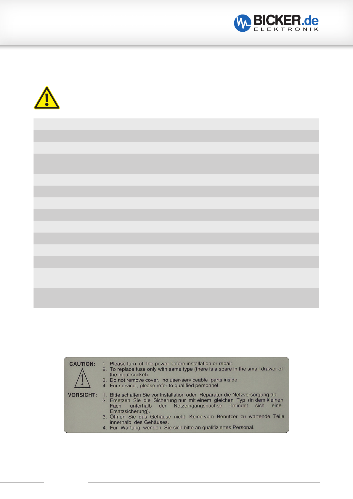
C Safety instructions ........................................................................................... 10
D Drawing............................................................................................................. 12
E Name / Address / Support E-Mail / Phone number of the manufacturer .... 12
F General Data ..................................................................................................... 13
F1 Assembly and installation advice............................................................................................................... 13
F2 Convection and installation position....................................................................................................... 13
F3 Description of connectors.............................................................................................................................. 14
F4 Connecting diagram .......................................................................................................................................... 15
G Operating .......................................................................................................... 16
G1 UPS on......................................................................................................................................................................... 16
G2 UPS off......................................................................................................................................................................... 16
G3 Cold start.................................................................................................................................................................... 16
G4 „oFF“ mode............................................................................................................................................................... 16
G5 SELF test button (1)............................................................................................................................................. 16
G6 ALARM RESET.......................................................................................................................................................... 17
G7 ALARM battery low.............................................................................................................................................. 17
G8 Battery charging.................................................................................................................................................... 17
G9 Settings....................................................................................................................................................................... 17
G10 LCD display............................................................................................................................................................... 17
G11 Change output frequency only for cold start (without mains)!.............................................. 17
G12 Change output voltage (in UPS mode).................................................................................................. 18
G13 Auto start of the UPS as soon as mains is present.......................................................................... 18
G14 Load sensor/green mode................................................................................................................................ 19
G15 LCD display and operating elements...................................................................................................... 20
G16 UPS back .................................................................................................................................................................... 21
H Optical and acoustic indicators....................................................................... 22
H1 Display in normal mode................................................................................................................................... 24
H2 Display in battery mode................................................................................................................................... 26
H3 Acoustic alarm........................................................................................................................................................ 27
H4 SELF TEST................................................................................................................................................................... 27
H5 Timer function........................................................................................................................................................ 27
H6 Reset the UPS.......................................................................................................................................................... 27
I Troubleshooting............................................................................................... 28
J Maintenance ..................................................................................................... 29
J1 Change of battery................................................................................................................................................ 30
J2 Disposal ...................................................................................................................................................................... 31
J3 Disclaimer.................................................................................................................................................................. 31

UPS-1000-B1
Revision 1 8
B Introduction and description
Read carefully before initial operation !
This manual shall help the user to get familiar with the product and its components and features. It shall
provide information as accurately and completely as possible.
The manual as well as all documents has to be read and followed strictly before installation. Otherwise in
certain situations warranty and guarantee can be cancelled partly or completely. Any liability on the part of
Bicker Elektronik is excluded for possible existing errors as well as non-compliance with the instructions for
use and installation.
B1 Description of the product and its functions
The UPS-1000-B1 is a uninterruptible Power Supply (UPS) with Line Interactive Design. In contrast to a con-
ventional off-line UPS, it has a sine voltage output. The UPS can be operated with a BP-2480 battery pack up
to +60 °C operating temperature.
The primary use of the UPS is to supply the connected application during power failures and /or voltage fluc-
tuations. The application which should be protected is connected to the output of the UPS.
In the event of a voltage drop or a voltage fluctuation of the input voltage (below undervoltage limit), the UPS
is switched to battery mode (also backup mode). In this state, the application at the UPS output is supplied via
the inside energy storage device. The backup time (also buffer time) depends on the available energy of the
installed battery pack, the level of the connected load current and the software settings of the UPS.
In the event of a power failure and the set backup time in UPSilon2000 has expired, the operating system of
the PC is shut down and the UPS is switched off.
In the event of a power failure and the return of the input voltage during the shutdown of the operating
system, the operating system is shut down by the UPS management software UPSilon2000. The UPS then
switches off the output for a short time. After a few seconds, this reboot function automatically switches back
to mains operation. The downstream PC can then automatically start here (BIOS setting PC). In addition, the
energy storages are recharged.

UPS-1000-B1
Revision 1 9
B2 Intended use
• The UPS is designed for the 230 V mains.
• The UPS-1000-B1 may only be installed in an upright position.
• Never install the UPS near liquids or in an excessively humid environment.
• Do not expose the UPS to direct sunlight or a heat source.
• After the initial installation to the AC mains, the battery starts to charge.
• It takes about 8 hours to fully charge.
• To minimize battery damage, the UPS has to be charged before storage and recharged every 6 months.
• The UPS must not be used as an inverter for any purpose other than that for which it was intended.
• The UPS is not designed for medical or life support systems.
• No laser printer or tube monitor may be connected to the UPS.
• It must be ensured that no foreign matter enters the UPS and that the fan outlet is always free.
• It must be ensured that the UPS-1000-B1 may only be loaded with maximum load. This value can be found
in the technical data in chapter A.

UPS-1000-B1
Revision 1 10
C Safety instructions
WARNING!
Disregarding of following issues can result in electric shock, fire, serious injury or death.
1. Care must be taken to ensure proper and professional wiring.
2. The device must not be exposed to fire and temperatures outside the specification.
3. The UPS is designed for the 230 V mains.
4. The device must not be operated in a damp environment or in an environment in which condensation
or condensation is to be expected.
5. The device must not be opened, short-circuited, reversed, overheated or otherwise modified.
6. Modifications or attempts to repair the device are to be omitted.
7. Effects of foreign objects on the device must be avoided (e.g. metal parts).
8. Do not put obviously damaged devices into operation (e.g. dents, burn marks, rough contamination).
9. Ventilation openings have to be kept free.
10. Device must not be dropped.
11. All parts of the device and accessories must not be eaten or swallowed.
12. The UPS may only be installed in an upright position.
13.
The UPS is supplied with voltage from both the 230 V power grid and the internal energy storage
device (battery). The latter is still live even after disconnecting the input source.
14. The UPS may only be loaded with 600 W / 1000 A max. according to the data sheet.
Note derating (page 13)!

UPS-1000-B1
Revision 1 11
1. Improper use and opening of the device will void the warranty/guarantee.
2. The device may only be used as intended.
3. The national accident prevention and safety regulations must be observed.
4. The assembly of the device and the electrical installation have to be state of the art.
5. The electrical, thermal and mechanical limit values have to be observed.
6. The UPS wiring specifications - as described in this manual - have to be followed.
7. After the initial installation to the AC power supply, the battery begins to charge.
It takes about 8 hours to fully charge.
8. To minimize battery damage, the UPS has to be charged before storage and recharged every 6 months.
9. The UPS must not be used as an inverter for any purpose other than that for which it was intended.
10. The UPS is not designed for medical or life support systems.
11. No laser printer or tube monitor may be connected to the UPS.
12. Safe handling of batteries, see page 29.
ATTENTION!

UPS-1000-B1
Revision 1 12
D Drawing
Unless otherwise stated,
Tolerance according to:
DIN ISO 2768 T1 - m
DIN ISO 2768 T2 - K
E Name / Address / Support E-Mail / Phone number of the manufacturer
Bicker Elektronik GmbH · Ludwig-Auer-Straße 23 · 86609 Donauwörth · Germany
18 cm
22 cm
46 cm

UPS-1000-B1
Revision 1 13
F General Data
F1 Assembly and installation advice
Installation and operation of this device is only allowed to be executed by a qualified
electrician! The application has to be separated from any power during the mounting process.
Wires have to be connected safely and must not have contact with sharp edges. Before com-
missioning, check all the connections for correctness!
Please check the shipping box for any transport damage immediately upon receipt. If you have any problems,
please contact your forwarding agent or parcel service. Please always send the UPS in the original box .
Plug the enclosed power cord into the UPS (2) and into a 3-pin
socket (with PE). Connect the load (e.g. PC) to the mains output of
the UPS (3). Plug the enclosed USB or green RS232 cable to USB and
PC and install UPSilon2000 on the PC.
The 3-pole mains connection of the UPS-1000-B1 has to be con-
nected to a 3-pole circuit (with PE / earth) protected with 16 A. The
sum of the leakage currents (UPS and connected devices) must not
exceed 3.5 mA. The UPS-1000-B1 can be live even in the event of
a power failure!
F2 Convection and installation position
• The UPS-1000-B1 may only be installed in an upright position.
• It must be ensured that the UPS-1000-B1 may bot be loaded beyond maximum load.
• This value can be found in the technical data in chapter A.
• Also mind the derating. This is to be calculated as follows:
600 W load at +40 °C. The permitted load to be connected is reduced by 10 W for every 1 K increase in
temperature. Thus, at +60 ° C, a maximum load of 400 W is permitted at the UPS output.
• It has to be ensured that no foreign matter enters the UPS and that the fan outlet is always free.
The following distances to neighboring devices are recommended:
Front: 50 mm
Back: 50 mm
Fan (right): 50 mm

UPS-1000-B1
Revision 1 14
F3 Description of connectors
The UPS offers two interfaces:
RS-232 or USB for the UPS management software UPSilon2000.
Only one can be used!
RS-232
PIN FUNCTION OPEN COLLECTOR Rx/Tx RS232
1 NC
2AC Power Failure (Open Collector)
Output
3 NC
4Connection/GND to 2 and 5
5Battery low (Open Collector)
Output
6Shutdown Signal (Input) RS232 Tx out
7Connection/GND to 6 Connection/GND to 6
and 9
8 NC
9 NC RS232 Rx in
The definition and setup for RS232 is shown as follows:
Baud rate: 2400 bps
Data length: 8 Bit
Stop Bit: 1 Bit
Parity: None
Open Collector
2, 5 Collector
4 GND
35 V, 10 mA (max)
no inductive load

UPS-1000-B1
Revision 1 15
F4 Connecting diagram
230 V
mains input
Interface USB or RS232
UPS output
RS232 or USB
RS232 USB
PC

UPS-1000-B1
Revision 1 16
G Operation
G1 UPS on
The UPS-1000-B1 is connected to the mains. The internal battery is being charged.
The internal battery is being charged. The battery level is displayed.
5
2.1 LCD-Anzeige und Bedienelemente
POWER ON/OFF Ein/Aus Taster
SELF TEST Selbsttest
ALARM RESET Alarm aus
LCD-Anzeige.
SELECT Auswahltasten für Modi und Einstellungen
1
2
3
If the automatic switch-on function is activated, the UPS switches on and activates the mains output sockets.
The current input voltage can be seen in the display. If the automatic switch-on function is deactivated, the
Power ON / OFF button (1) must be pressed to switch on.
G2 UPS off
If the Power ON / OFF button (1) is pressed for 4 seconds, the UPS switches off the mains output sockets and
the UPS switches off after approx. 10 seconds. „oFF“ appears in the display. The battery is charged even when
the UPS is switched off.
G3 Cold start
The UPS can be switched on without a mains input. To do this, the Power ON / OFF button (1) has to be pressed
for one second. „oFF“ appears in the display. Then press the Power ON / OFF button (1) again!
G4 „oFF“ mode
In „oFF“ mode, the UPS switches off within 10 seconds in the event of a power failure.
In „oFF“ mode, the UPS switches itself off within 10 seconds when the mains cable is disconnected.
G5 SELF test button (1)
For a battery load test, the mains lead can be disconnected for a mains failure simulation. However, if the SELF
test button (1) is pressed instead of unplugging the mains lead, the UPS switches off the mains internally for
10 seconds for a load test.
The application or e.g. a 100 W incandescent lamp can be used as load. To cancel the self-test, the SELF test
button (1) can be pressed for 2 seconds.

UPS-1000-B1
Revision 1 17
G6 ALARM RESET
In the event of a power failure, the buzzer beeps twice every 8 seconds. The alarm can be switched off and on
again by pressing the alarm reset button (1). The loudspeaker symbol appears in the LCD display. With a 0 W
load, the alarm reset button (1) has no function.
G7 ALARM battery low
If the battery voltage is too low (in UPS mode), the buzzer gives several warnings.
The deep discharge protection then switches off the UPS.
Note:
In mains operation the function of button (1) is >> SELF test (G5)
In UPS operation the function of button (1) is >> ALARM RESET (G6)
G8 Battery charging
The UPS offers two charging modes for the batteries. A quick charging and a trickle charging. Quick charging
provides a higher charging current when the battery is empty and reduces the charging current when the
battery voltage increases. Trickle charging starts automatically, after the battery is 90 % charged.
G9 Settings
There are two ways to change the setting on the UPS. Via software in the factory or settings via the LCD display.
G10 LCD display
Press the two selection buttons and at the same time for 3 seconds until the LCD display starts to flash.
You can continue through the menu if you press both buttons again at the same time.
G11
Change output frequency of the UPS only for cold start (without mains)!
When the frequency value is flashing, press any selection button or for 1 second to chance the frequency
settings! The settings keep changing every 2 seconds, if you press the button.
Press again the two selection buttons at the same time for the next setting. If you do not press it again, the LCD
display will stop flashing after 30 seconds and the setting will be completed.
10
4.10 Einstellungen
Es gibt zwei Möglichkeiten um die Einstellung an der USV zu ändern. Per Software in der Fabrik
bzw. Einstellungen über das LCD Display.
4.11.1 LCD Display
Drücken Sie die beiden Auswahltasten △und ▽gleichzeitig für 3 Sekunden, bis die
LCD-Anzeige zu blinken beginnt. Durch das Menü gelangen Sie weiter, wenn abermals wieder
beide Tasten gleichzeitig gedrückt werden.
4.11.2 Ausgangsfrequenz der USV nur für „Kaltstart“ (ohne Netz) ändern!
Wenn der Frequenzwert blinkt, drücken Sie eine beliebige Auswahltaste △bzw. ▽für 1
Sekunde, um die Frequenzeinstellung zu ändern! Die Einstellung wird sich alle 2 Sekunden
ändern, wenn man die Taste betätigt.
Drücken Sie wieder die zwei Auswahltasten gleichzeitig zur nächsten Einstellung. Ohne weitere
Betätigung wird das LCD Display nach 30 Sekunden aufhören zu blinken und die Einstellung
beenden.
4.11.3 Ändern der Ausgangsspannung im USV Betrieb.
Wenn der Ausgangsspannung Wert blinkt, drücken Sie eine beliebige Auswahltaste △bzw. ▽
für 1 Sekunde, um die Ausgangsspannung zu ändern! Die Einstellung wird sich alle 2 Sekunden
ändern, wenn man die Taste betätigt.
Zum nächsten Menüpunkt gelangen Sie durch gleichzeitiges Drücken der beiden Auswahltasten
△und ▽.Ohne weitere Betätigung wird das LCD Display nach 30 Sekunden aufhören zu blinken
und die Einstellung beenden.

UPS-1000-B1
Revision 1 18
G12 Change output voltage (in UPS mode)
When the output voltage value is flashing, press any selection button or for 1 second, to change the out-
put voltage! The settings keep changing every 2 seconds, if you press the button.
10
4.10 Einstellungen
Es gibt zwei Möglichkeiten um die Einstellung an der USV zu ändern. Per Software in der Fabrik
bzw. Einstellungen über das LCD Display.
4.11.1 LCD Display
Drücken Sie die beiden Auswahltasten △und ▽gleichzeitig für 3 Sekunden, bis die
LCD-Anzeige zu blinken beginnt. Durch das Menü gelangen Sie weiter, wenn abermals wieder
beide Tasten gleichzeitig gedrückt werden.
4.11.2 Ausgangsfrequenz der USV nur für „Kaltstart“ (ohne Netz) ändern!
Wenn der Frequenzwert blinkt, drücken Sie eine beliebige Auswahltaste △bzw. ▽für 1
Sekunde, um die Frequenzeinstellung zu ändern! Die Einstellung wird sich alle 2 Sekunden
ändern, wenn man die Taste betätigt.
Drücken Sie wieder die zwei Auswahltasten gleichzeitig zur nächsten Einstellung. Ohne weitere
Betätigung wird das LCD Display nach 30 Sekunden aufhören zu blinken und die Einstellung
beenden.
4.11.3 Ändern der Ausgangsspannung im USV Betrieb.
Wenn der Ausgangsspannung Wert blinkt, drücken Sie eine beliebige Auswahltaste △bzw. ▽
für 1 Sekunde, um die Ausgangsspannung zu ändern! Die Einstellung wird sich alle 2 Sekunden
ändern, wenn man die Taste betätigt.
Zum nächsten Menüpunkt gelangen Sie durch gleichzeitiges Drücken der beiden Auswahltasten
△und ▽.Ohne weitere Betätigung wird das LCD Display nach 30 Sekunden aufhören zu blinken
und die Einstellung beenden.
To get to the next menue item, press both selection buttons and at the same time. If you do not press it
again, the LCD display will stop flashing after 30 seconds and the setting will be completed.
G13 Auto recovery of UPS as soon as mains is present
If the automatical on/off function flashes, press any selection button or for 1 second, to change switch on/
off! The settings keep changing every 2 seconds, if you press the button.
off >> No auto recovery as soon as mains is present
On >> Auto recovery as soon as mains is present
On. S >> Auto recovery in “safety mode” as soon as mains is present
If the battery is still discharged from the previous UPS operation, the output of the UPS is only switched on after
the battery has been charged (at least 30 %).
To get to the next menue item, press both selection buttons and . If you do not press it again, the LCD
display will stop flashing after 30 seconds and the setting will be completed.
11
4.11.4 Automatische Einschaltung der USV sobald Netz anliegt
Wenn die automatische Ein bzw. Aus Funktion blinkt, drücken Sie eine beliebige Auswahltaste △
bzw. ▽für 1 Sekunde, um die Ein/Ausschaltung zu ändern! Die Einstellung wird sich alle 2
Sekunden ändern, wenn man die Taste betätigt.
off Keine automatische Einschaltung sobald das Netz anliegt
On Automatische Einschaltung sobald das Netz anliegt
On. S Automatische Einschaltung im “Sicherheitsmodus” sobald das Netz anliegt
Falls die Batterie noch vom vorherigen USV Betrieb entladen sein sollte wird der Ausgang der USV
erst nach Ladung der Batterie (ca. 30%) zugeschgaltet.
Zum nächsten Menüpunkt gelangen Sie durch gleichzeitiges Drücken der beiden Auswahltasten
△und ▽.Ohne weitere Betätigung wird das LCD Display nach 30 Sekunden aufhören zu blinken
und die Einstellung beenden.

UPS-1000-B1
Revision 1 19
G14 Load sensor / Green Mode
Scenario: The PC is shut down manually using the mouse (with , on / off, shutdown), followed by
a „power failure“ by e.g. the EVU. A standard UPS without a load sensor would switch to battery operation and
buffer the standby mode of the switched-off PC until the battery is discharged. By switching on and adjusting
the load sensor / green mode on the UPSI-1000-B1, the connected load can be thrown off if it falls below the
limit.
When Gn.x (x: number) flashes, press any selection button or for 1 second to change the load sensor! The
settings keep changing every 2 seconds, if you press the button.
Gn.0: Load sensor is deactivated.
Gn.1…9: Load sensor / green mode is deactivated and can 1…9 % of the nominal load of the UPS (600 W).
To get to the next menue item, press both selection buttons and . If you do not press it again, the LCD
display will stop flashing after 30 seconds and the setting will be completed.
12
4.11.5 Lastsensor/Green Modus
Szenario:
Ein PC wird manuell per Maus (Windows: Start/Beenden/Herunterfahren) heruntergefahren. Dann
gäbe es einen Stromausfall durch das EVU oder es könnte auch ein vorgeschalteter Netzschalter
einer Maschine ab geschalten werden! In diesem Fall würde die USV in den Batteriebetrieb
schalten und die Stand By Schaltung des PC’s oder das angeschlossene Netzteils puffern bis die
Batterie entladen ist. Durch Einschalten und Justierung des Lastsensors/Green Modus kann die
angeschlossene Last bei Unterschreiten abgeworfen werden.
Wenn Gn.x (x Zahl) blinkt, drücken Sie eine beliebige Auswahltaste △bzw. ▽für 1 Sekunde,
um den Lastsensor zu ändern! Die Einstellung wird sich alle 2 Sekunden ändern, wenn man die
Taste betätigt.
Gn.0 Der Lastsensor ist deaktiviert.
Gn.1….9 Der Lastsensor/Green Modus ist deaktiviert und kann von 1…9% der nominalen
Leistung der USV (600W).
Zum nächsten Menupunkt gelangen Sie durch gleichzeitiges Drücken der beiden Auswahltasten
△und ▽.Ohne weitere Betätigung wird das LCD Display nach 30 Sekunden aufhören zu blinken
und die Einstellung beenden.

UPS-1000-B1
Revision 1 20
G15 LCD display and operating elements
5
2.1 LCD-Anzeige und Bedienelemente
POWER ON/OFF Ein/Aus Taster
SELF TEST Selbsttest
ALARM RESET
Alarm aus
LCD-Anzeige.
SELECT Auswahltasten für Modi und Einstellungen
1
2
3
POWER ON/OFF >> On/Off button
SELF-TEST >> Self test
ALARM RESET >> Alarm off
LCD display
SELECT >> Selection button for modes and settings
Table of contents
Other Bicker UPS manuals

Bicker
Bicker UPSI-1208DP Series User manual

Bicker
Bicker UPSI-2403 User manual

Bicker
Bicker UPSI-1208DPx User manual

Bicker
Bicker IUPS-401-B8 User manual

Bicker
Bicker IUPS-401-B1 User manual

Bicker
Bicker UPSI-2406DP Series User manual

Bicker
Bicker UPSI-IP-3 Series User manual

Bicker
Bicker UPSI-1208D User manual