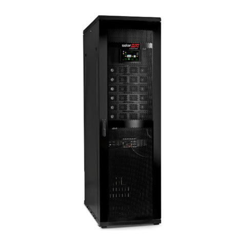
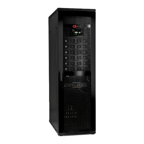
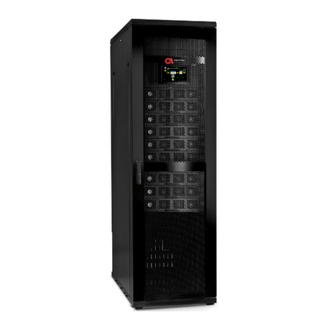
SolarEdge Gamatronic B300 User manual

GAMATRONIC
THREE PHASE MODULAR UPS
FOR THE 400V GRID
B300
INSTALLATION GUIDE
Revision 3.0, January 2020 (Doc. 2MUM-B300I)
This installation
guide is for product
101SKD60

iii
UPS for 400 Vac Grid, Installation Guide, doc. rel. 3.0
STANDARDS AND CONVENTIONS
This user manual contains diagrams which include images of the display screen of the UPS. Unless
otherwise indicated, the readings shown in the screen images are only illustrative, and are not
intended to match the readings on a specific system in any particular environment.
Operation and control of the UPS is accomplished through a touch-sensitive LCD display screen. In
this manual, when explaining how to navigate the control software via the touch-sensitive screen,
the terms "tap", "press", "choose", and "select" may be used interchangeably to indicate selection
of a screen option.
Most of the electrical abbreviations in this document are according to IEEE 280 Standard Letter
Symbols for Quantities Used in Electrical Science and Electrical Engineering.

iv
Three Phase Modular UPS, Installation Guide, rel.2.0
TABLE OF CONTENTS
1. UNPACKING INSTRUCTIONS............................................................................................................................. 1
2. SAFETY PRECAUTIONS...................................................................................................................................... 4
DO’S..............................................................................................................................................................................4
DON’TS...........................................................................................................................................................................5
3. SYSTEM STRUCTURE AND INSTALLATION......................................................................................................... 7
3.1. IMPORTANT INSTALLATION INFORMATION............................................................................................... 11
3.2. INSTALLATION CHECKLIST .......................................................................................................................... 12
3.3. INSTALLATION PROCEDURE ....................................................................................................................... 23
3.3.1. Visual Inspection ..................................................................................................................................23
3.3.2. Site Preparation –Physical...................................................................................................................23
3.3.3. Site Preparation –Electrical .................................................................................................................25
3.3.4. Cabling .................................................................................................................................................26
3.3.4.1. The Ground Line ............................................................................................................................................... 26
3.3.4.2. The Neutral Line ............................................................................................................................................... 27
3.3.4.3. Ac input and output connections ..................................................................................................................... 27
3.3.4.4. Connecting the UPS to the electrical panel ...................................................................................................... 31
3.3.4.5. Assembling and connecting external batteries ................................................................................................ 33
3.3.5. Powering up the system .......................................................................................................................37
3.3.5.1. Before starting up the UPS ............................................................................................................................... 37
3.3.6. Initial Configuration .............................................................................................................................38
3.3.6.1. System Startup Wizard..................................................................................................................................... 38
3.3.6.2. Continuing first time startup process............................................................................................................... 42
3.3.6.3. Assigning IP Address to the UPS ....................................................................................................................... 49
3.4. TESTING ..................................................................................................................................................... 52
3.4.1. Test: Self-loading/PQ mode..................................................................................................................52
3.4.2. Test: Under load ...................................................................................................................................55
3.4.3. Test: Battery and blackout mode .........................................................................................................56
3.4.4. Test: ATS...............................................................................................................................................56
3.4.5. Test: ECO Mode ....................................................................................................................................58
3.4.6. Test: IP Communication with Controller...............................................................................................61
4. AUXILIARY CONNECTIONS.............................................................................................................................. 63
4.1. INPUT AND OUTPUT DRY CONTACTS ......................................................................................................... 68
4.2. EMERGENCY POWER OFF –EPO (MANUAL) ............................................................................................... 69
4.2.1. Restarting the UPS after EPO ...............................................................................................................69
4.3. SURGE PROTECTOR MALFUNCTION ALARM............................................................................................... 70
4.4. LVD BATTERY PROTECTOR ......................................................................................................................... 71
5. CIRCUIT BREAKER SELECTIVITY....................................................................................................................... 72
6. PARALLEL OPERATION ................................................................................................................................... 74
6.1. THEORY...................................................................................................................................................... 74
6.1.1. Decentralized static switch method .....................................................................................................74
6.1.2. Parallel communication........................................................................................................................75

UPS for 400 Vac Grid, Installation Guide, doc. rel. 2.0
v
6.1.2.1. EPO and parallel operation .............................................................................................................................. 77
6.1.2.2. Common vs. Decentralized battery .................................................................................................................. 77
6.2. INSTRUCTIONS FOR PARALLEL CONFIGURATION ....................................................................................... 77
6.2.1. Maintenance bypass for parallel systems ............................................................................................85
7. PROCEDURE: MAINTENANCE BYPASS MODE ................................................................................................. 86
7.1. CIRCUIT BREAKER LAYOUT......................................................................................................................... 87
7.2. TRANSFERRING THE UPS TO MAINTENANCE BYPASS MODE FROM NORMAL MODE ................................. 88
7.3. TRANSFERRING THE UPS BACK TO NORMAL MODE FROM MAINTENANCE BYPASS MODE........................ 90
8. USING THE UPS WITH A GENERATOR ............................................................................................................. 91
8.1. THE AUTOMATIC TRANSFER SWITCH (ATS) ............................................................................................................91
9. SERVICE AND REPAIRS ................................................................................................................................... 93

vi
UPS for 400 Vac Grid, Installation Guide, doc. rel. 3.0
LIST OF FIGURES
FIGURE 1: INSPECT THE SHIPPING CRATE FOR SIGNS OF DAMAGE ....................................................................................................1
FIGURE 2: SHOCKWATCH AND TILTWATCH DEVICES ....................................................................................................................2
FIGURE 3: REMOVE THE ROOF AND SUPPORT BEAM (USE ELECTRIC SCREWDRIVER) .............................................................................3
FIGURE 4: REMOVE THE WALLS OF THE CRATE ............................................................................................................................3
FIGURE 5: MAJOR UPS COMPONENTS (FRONT VIEW)..................................................................................................................7
FIGURE 6: MAIN TERMINALS VIEWED FROM THE UPS REAR ..........................................................................................................9
FIGURE 7: DIMENSIONS OF THE GAMATRONIC UPS ..................................................................................................................24
FIGURE 8: RECOMMENDED CLEARANCES AROUND THE UPS........................................................................................................25
FIGURE 9: RECOMMENDED SYSTEM CONNECTIONS ....................................................................................................................28
FIGURE 10: RECOMMENDED CONNECTIONS WITH INPUT ISOLATION TRANSFORMER.........................................................................29
FIGURE 11: TERMINAL CONNECTIONS .....................................................................................................................................30
FIGURE 12: CONNECTING A SINGLE BATTERY SET ......................................................................................................................34
FIGURE 13: CONNECTING MULTIPLE BATTERY SETS,USING CBS...................................................................................................35
FIGURE 14: INITIAL CONFIGURATION WIZARD:START SCREEN......................................................................................................38
FIGURE 15: INITIAL CONFIGURATION WIZARD:PASSWORD ENTRY ................................................................................................39
FIGURE 16: INITIAL CONFIGURATION WIZARD:BATTERY CAPACITY IN AH.......................................................................................39
FIGURE 17: INITIAL CONFIGURATION WIZARD:SET TIME ZONE .....................................................................................................40
FIGURE 18: EXIT CONFIGURATION WIZARD ..............................................................................................................................41
FIGURE 19: FLAT CABLES ......................................................................................................................................................42
FIGURE 20: STATIC SWITCH ...................................................................................................................................................42
FIGURE 21: MODULES ON SCREEN .........................................................................................................................................43
FIGURE 22: MODULES OFF SCREEN ........................................................................................................................................43
FIGURE 23: MODULES ON SCREEN .........................................................................................................................................44
FIGURE 24: CONFIRM DISCONNECTING THE LOAD .....................................................................................................................45
FIGURE 25: CONFIRM SWITCH ON ALL MODULES......................................................................................................................45
FIGURE 26: THE ALARMS ICON INDICATES ALARM CONDITIONS....................................................................................................46
FIGURE 27: NEXT SCHEDULED TEST SCREEN ..............................................................................................................................46
FIGURE 28: BATTERY TEST IN PROGRESS SCREEN .......................................................................................................................47
FIGURE 29: CONFIRM TRANSFER LOAD TO BYPASS ....................................................................................................................47
FIGURE 30: CONFIRM TRANSFER LOAD TO INVERTER DIALOG.......................................................................................................48
FIGURE 31: SET LAST MAINTENANCE DATE SCREEN ...................................................................................................................48
FIGURE 32: CONFIRM SAVE USER SETTINGS .............................................................................................................................49
FIGURE 33: IP ADDRESS CONFIGURATION................................................................................................................................50
FIGURE 34: IP ADDRESS CONFIGURATION ................................................................................................................................51
FIGURE 35: ENABLE SELF-LOADING/PQ MODE .........................................................................................................................53
FIGURE 36: SELF-LOADING/PQ MODE SETUP............................................................................................................................53
FIGURE 37: SELF-LOADING/PQ MODE ....................................................................................................................................54
FIGURE 38: REACTIVE LOAD TESTING.......................................................................................................................................54
FIGURE 39: DISABLE PQ MODE..............................................................................................................................................55
FIGURE 40: GENERATOR MODE..............................................................................................................................................57
FIGURE 41: CHANGING THE AUXILIARY CONTACT TO NORMALLY CLOSED.........................................................................................58
FIGURE 42: ECO MODE SCREEN -ENABLED CHECKBOX ..............................................................................................................59
FIGURE 43: TURNING ON ECO MODE.....................................................................................................................................60
FIGURE 44: STATUS SCREEN,UPS ON AND ECO MODE ON.......................................................................................................60
FIGURE 45: WEB VIEW ........................................................................................................................................................62
FIGURE 46: LOCATION OF CONNECTOR GROUPS 1AND 2ON THE FRONT OF THE UPS .....................................................................63

UPS for 400 Vac Grid, Installation Guide, doc. rel. 2.0
vii
FIGURE 47: CLOSE-UP OF CONNECTOR GROUP 1......................................................................................................................64
FIGURE 48: CONNECTOR GROUP 2.........................................................................................................................................65
FIGURE 49: FOUR PIN CONNECTORS .......................................................................................................................................68
FIGURE 50: LVD WIRING DIAGRAM ........................................................................................................................................71
FIGURE 51: AUPS'S BYPASS CIRCUIT .....................................................................................................................................72
FIGURE 52: THE STATIC SWITCH IN CONTEXT (STAND-ALONE SYSTEM)...........................................................................................74
FIGURE 53: PARALLEL COMM.CONNECTIONS (SEE TABLE 9) .......................................................................................................75
FIGURE 54: LOCATION OF THE PARALLEL COMM.CONNECTIONS AT INSIDE-REAR OF THE SYSTEM ........................................................76
FIGURE 55: COMMON DC PARALLEL COMMUNICATION CABLE....................................................................................................79
FIGURE 56: DECENTRALIZED DC PARALLEL COMMUNICATION CABLE.............................................................................................79
FIGURE 57: THE SYSTEM MENU SCREEN .................................................................................................................................80
FIGURE 58: THE CROWN ICON INDICATES THE MASTER UPS .......................................................................................................81
FIGURE 59: AC OUTPUT VOLTAGE DISPLAY FOR A SINGLE MODULE................................................................................................81
FIGURE 60: CONNECTION DIAGRAM FOR 2PARALLEL UNITS ........................................................................................................83
FIGURE 61: CONNECTION DIAGRAM FOR 4UNITS IN PARALLEL ....................................................................................................84
FIGURE 62: ELECTRICAL SETUP...............................................................................................................................................87
FIGURE 63: POSITION OF THE CBS IN NORMAL MODE.................................................................................................................90
FIGURE 64: TIMING VARIABLES WHEN USING A GENERATOR AND AN ATS ......................................................................................91
FIGURE 65: EXAMPLE OF AN ATS CONTROL PANEL.....................................................................................................................92

viii
UPS for 400 Vac Grid, Installation Guide, doc. rel. 3.0
LIST OF TABLES
TABLE 1: KEY TO FIGURE 5......................................................................................................................................................8
TABLE 2: KEY TO FIGURE 6......................................................................................................................................................9
TABLE 3: RECOMMENDED CLEARANCES...................................................................................................................................25
TABLE 4: RECOMMENDED CIRCUIT BREAKERS FOR THE CURRENT RATING FOR 30-300KVA 400V UPS .................................................32
TABLE 5: BATTERY CURRENT RATINGS FOR SEMICONDUCTOR FUSES AND CIRCUIT BREAKERS ...............................................................34
TABLE 6: BATTERY LIFETIME VS ENVIRONMENTAL TEMP.(ILLUSTRATIVE,AS PER EUROBAT)................................................................36
TABLE 7: KEY TO FIGURE 47 .................................................................................................................................................64
TABLE 8: DESCRIPTION OF CONNECTOR GROUP 2(KEY TO FIGURE 48).........................................................................................65
TABLE 9: CABLE SETS FOR PARALLEL COMMUNICATION BETWEEN UPSS.........................................................................................78
TABLE 10: RATING OF CB12 (FOR MAINTENANCE BYPASS OPTION) ..............................................................................................85
TABLE 11: NORMAL MODE OPERATING POSITION OF THE CIRCUIT BREAKERS ...................................................................................88
TABLE 12: POSITION OF THE CBS IN MAINTENANCE BYPASS MODE................................................................................................89
TABLE 13: MAINTENANCE BYPASS OPERATING POSITION OF THE CIRCUIT BREAKERS..........................................................................90

UPS for 400 Vac Grid, Installation Guide, doc. rel. 3.0
1
1. Unpacking Instructions
1. Inspect the shipping crate for any signs of damage that may have occurred while in
transit.
Figure 1: Inspect the shipping crate for signs of damage
2. Inspect the ShockWatch and TiltWatch devices, which are adhered to the outside of the
wooden packing crate. Verify that their indicators are not red.
A red indicator is a sign of rough handling (ShockWatch) or tip-over (TiltWatch).
Notify the carrier and Gamatronic Support immediately if rough handling of the
UPS is suspected or if any damage is found or suspected.
3. Retain the shipping crate and packaging materials for future use.

2
UPS for 400 Vac Grid, Installation Guide, doc. rel. 3.0
- OR -
Figure 2: ShockWatch and TiltWatch devices
These devices indicate if the package was subject to shock or tip-over.
4. Using a forklift, move the shipping crate close to the place in which the UPS will be
installed.
5. Cut and remove any straps that are on the shipping crate.
6. Stand on a secure ladder and use an electric screwdriver to remove the screws that are
holding the roof of the shipping crate in place. Then remove the roof.

UPS for 400 Vac Grid, Installation Guide, doc. rel. 3.0
3
Figure 3: Remove the roof and support beam (use electric screwdriver)
7. Remove the screws that are holding the walls and support beams of the crate in place.
Then carefully remove the walls themselves leaving the UPS standing on its wooden
shipping pallet.
Figure 4: Remove the walls of the crate
8. Cut and remove any straps that are securing the UPS to the shipping pallet.
9. Remove the plastic wrapping and all other packaging material from the UPS.
Be careful to avoid scratching the finish of the Modular UPS.
10. Lift the UPS from the shipping pallet and move it to the location where it will be
installed.

4
UPS for 400 Vac Grid, Installation Guide, doc. rel. 3.0
2. Safety Precautions
The UPS system is designed for a wide range of environments. Nevertheless, the modular UPS
should be handled with care, according to the following guidelines.
Do’s
Read this manual and the User Guide carefully before starting installation and operation of the
UPS.
Review the safety precautions described below to avoid injury to users and damage to the
equipment.
This UPS is intended for installation in a temperature-controlled, indoor area that is free from
conductive contaminants.
All power connections must be completed by a licensed electrician who is experienced in
wiring this type of equipment, and who is familiar with the local electrical codes and
regulations. Improper wiring may cause damage to the equipment, injury to personnel, or
even death.
Ensure all power is disconnected before performing installation or maintenance.
See Table 3 and Figure 7 for recommended clearances.
The UPS must be well grounded to the building’s grounding system with a conductor that has
a current carrying capacity that matches the rating of the UPS, according to local codes.
Battery installation, battery maintenance, and battery replacement shall be performed only by
authorized service personnel.
Pay attention to all DANGER, CAUTION, and WARNING notices affixed to the inside and
outside of the UPS.
Keep the surroundings clean, uncluttered and free from excess moisture.
Keep the operating environment within the parameters stated in this document.
Allow only qualified technicians to service the UPS. There are no user-serviceable components.
Do not try to repair it yourself!
Use the UPS only for its intended purpose.
The batteries should preferably be installed next to the UPS, or as close to it as is practically
possible.

UPS for 400 Vac Grid, Installation Guide, doc. rel. 3.0
5
If you remove a power module from the UPS while the module is operating, wait five minutes
before reinserting the module. This allows the module’s capacitors time to discharge.
FAST FUSES (SEMICONDUCTOR FUSES) must be used between the battery and the UPS –for
example, the Ferraz Shawmut A70QS fuse.
WARNING - RISK OF LETHAL ELECTRIC SHOCK:
WARNING! HIGH TOUCH CURRENT!
EARTH CONNECTION ESSENTIAL BEFORE CONNECTING SUPPLY.
WARNING - RISK OF LETHAL ELECTRIC SHOCK:
The battery cabinet contains a series of batteries that provides high
voltage and energy in the UPS body even when the UPS is not
connected to the ac input.
Take appropriate precautions during installation, inspection and
servicing.
Don’ts
Do not open the cover of the UPS or the battery cabinets under any circumstances. All UPS
panels and doors should be closed.
Do not insert any objects through the ventilation holes.
Do not put objects on the UPS.
Do not move the UPS while it is operating.
Do not use the UPS outdoors.
Do not turn the UPS upside down or lying down during transportation.
Do not connect or disconnect any AC or DC cables to the battery cabinet or UPS unless ALL
the battery circuit and AC circuit breakers are turned OFF.
Do not turn ON the battery circuit breaker when the battery cabinet is disconnected from the
UPS.
Do not install the UPS next to gas or electrical heaters. A restricted location is recommended
in order to prevent access by unauthorized personnel.

6
UPS for 400 Vac Grid, Installation Guide, doc. rel. 3.0
If you remove a power module from the UPS while the module is operating, do not reinsert
the module immediately. Wait five minutes.
WARNING - RISK OF LETHAL ELECTRIC SHOCK:
This UPS receives power from more than one source!
Disconnection of all ac sources and dc sources is
required to de-energize this unit before servicing.
WARNING - RISK OF LETHAL ELECTRIC SHOCK:
Do not touch uninsulated battery terminals.

UPS for 400 Vac Grid, Installation Guide, doc. rel. 3.0
7
3. System Structure and Installation
The UPS is composed of:
Up to 10 power modules, each providing 30 kVA/30 kW
Static switch module
System controller
Maximum output capacity of the UPS is 300 kVA/300 kW.
Figure 5: Major UPS components (front view)

8
UPS for 400 Vac Grid, Installation Guide, doc. rel. 3.0
Table 1: Key to Figure 5
Item
Description
A
The system controller and the LCD screen combined.
B
The UPS cabinet’s front door
C
Power modules. Each supplies 30 kVA / 30 kW.
D
Removable static switch and 5 dry contacts. “Connector group 1”.
E
Dry contacts and communication connections. “Connector group 2”.
F
Main ac and dc connections
G
BYPASS INPUT terminals (L1, L2, L3, reading from back to front)
H
AC INPUT terminals (L1, L2, L3, reading from back to front)
I
AC OUTPUT terminal connections (L1, L2, L3, reading from back to front)
J
BATTERY connections (positive, midpoint {neutral}, negative reading from back to
front)
N
Neutral bus bar (same as Midpoint) (behind terminal J- not seen in picture)
Protective earth (ground) bus bar

UPS for 400 Vac Grid, Installation Guide, doc. rel. 3.0
9
Figure 6: Main terminals viewed from the UPS rear
Table 2: Key to Figure 6
Item
Description
1
Bypass Input (L1)
2
Bypass Input (L2)
3
Bypass Input (L3)
4
Ac Input (L1)
5
Ac Input (L2)
6
Ac Input (L3)
7
Ac Output (L1)
8
Ac Output (L2)
9
Ac Output (L3)
10
Positive battery terminal (+)
11
Battery midpoint and Neutral bus bar.
12
Negative battery terminal (–)
Protective earth (ground) bus bar

10
UPS for 400 Vac Grid, Installation Guide, doc. rel. 3.0
ALL POWER CONNECTIONS MUST BE COMPLETED BY A LICENSED
ELECTRICIAN WHO IS EXPERIENCED IN WIRING THIS TYPE OF EQUIPMENT,
AND WHO IS FAMILIAR WITH THE LOCAL ELECTRICAL CODES AND
REGULATIONS.
IMPROPER WIRING MAY CAUSE INJURY TO PERSONNEL AND/OR DAMAGE
TO THE EQUIPMENT.
IN THE EVENT THAT THE UPS HAS BEEN DISCONNECTED FROM THE AC
MAINS FOR FOUR MONTHS OR LONGER FOLLOWING ITS DELIVERY TO
THE CUSTOMER SITE,THE UPS MUST BE CONNECTED TO THE AC MAINS
AND OPERATED WITH NO LOAD FOR A PERIOD OF FOUR HOURS,BEFORE
APPLYING A LOAD.

UPS for 400 Vac Grid, Installation Guide, doc. rel. 3.0
11
3.1. Important Installation Information
The Gamatronic UPS must be connected a “4-wire + Ground” configuration (i.e., 3 phases +
Neutral + Ground). The voltage displayed on the status screen is the Phase-to-Neutral voltage.
The Neutral line MUST be connected to the UPS on the input and output stages of the UPS. The
UPS will support phase-to-phase loads and phase-to-Neutral loads. The Neutral line must always
remain connected when the UPS is operating. All input, output and dc cables must be armored,
and the armored layer must be connected to the UPS ground connection terminals only.

12
UPS for 400 Vac Grid, Installation Guide, doc. rel. 3.0
3.2. Installation Checklist
Complete the following checklist as you perform the installation, initialization, configuration, and
testing procedures. Refer to the appropriate sections (specified in the Reference column) for
detailed information about each checklist item. The detailed explanation of each section can be
found in Section 3.3 and Section 0.
When the checklist is complete, e-mail it to your vendor and to Gamatronic
Support@gamatronic.com.
INSTALLATION CHECKLIST FOR THE GAMATRONIC MODULAR UPS .
Customer
Address
Site
Phone
E-mail
Serial numbers: System _________________Static Switch ____________________
Modules 1___________ 2___________ 3___________4___________ 5___________ 6___________
7___________8___________ 9___________ 10___________
Technician Name
Date
Signature
√
Activity
Requirement
Reference
Visual Inspection
1. Verify the physical integrity of the
system.
No physical damage.
3.3.1
In case of physical damage, photograph the damage and describe it here:
_____________________________________________________________________________________
Table of contents
Other SolarEdge UPS manuals

