Bicker UPSI-1208DPx User manual

User Manual UPSI-1208DPx
Bicker Elektronik GmbH
Ludwig-Auer-Straße 23 |86609 Donauwörth·Germany
English
UPS SYSTEM
DIN-RAIL

UPSI-1208DPx
Revision 2-0 2
Revision Directory
Date Change
31.03.2020
Revision 0-1
Initial version
10.06.2020
Revision 1
Release version
03.07.2020
Revision 1-1
Chapter B2 extended,
Chapter B3 Environmental condition extended,
Chapter C1 Input data Internal input fuse changed
Chapter C1 Environmental conditions extended.
16.07.2020
Revision 1-2
PELV indication removed
09.11.2020
Revision 1-3
Chapter B3 Intended use more detailed specified
Chapter C1 Environmental conditions more detailed specified
(Indoor/Outdoor)
Page 2, Warning „Read User Manual“ at explanation „Legend of used
symbols“ supplemented
25.11.2020
Revision 1-4
Model UPSI-1208DP3 integrated
20.10.2021
Revision 1-5
Basic revision of individual chapters, updated backup time diagrams, B
rebuilt, E14 software removed, F9 rebuilt, F12 status LED rebuilt, new image
in F5, E5 images removed, F13 Shutdown diagramm added
25.04.2022
Revision 2-0
Brief specifications divided (DP2, DP3), technical data updated,
pictures updated, F12 Dynamic Powerboost added
Legend of used symbols
Symbol Description
Attention! Important hazard warning.
Do not dispose of in the domestic waste.
Warning of electrical voltage.
UPSI-1208DPx
Revision 2-0 3
Input voltage 12 V DC (11.5…16 V)
Input current 9 A max.
Output voltage Normal mode: VIN– 0.6 V DC max. (depending on load)
Battery mode: 12 V DC
Output current 8 A nominal
Capacitive load 3000 µF (in normal mode, at start, 0A load)
Charging method CC/ CV/CP
Protection Input: Reverse polarity protection
Output: Overcurrent protection, Short circuit protection
Interface USB, RS232, HID UPS
Battery technology EDLC 5.73 kJ (3.88 kJ useful) / 1.59 Wh (1.08 Wh useful)
Ambient temperature Operating Storage / Transport
-20…+65°C -30…+65°C
Operating altitude ≤4000 m
Max. permitted humidity ≤95 % (at +25°C, no dew)
Dimensions W/ H / D 63 x 120 x 100 mm
(without front connectors and DIN-Rail mounting bracket)
Weight 0.6 kg
Technical Data
UPSI-1208DP2
12 V DC / 8 A
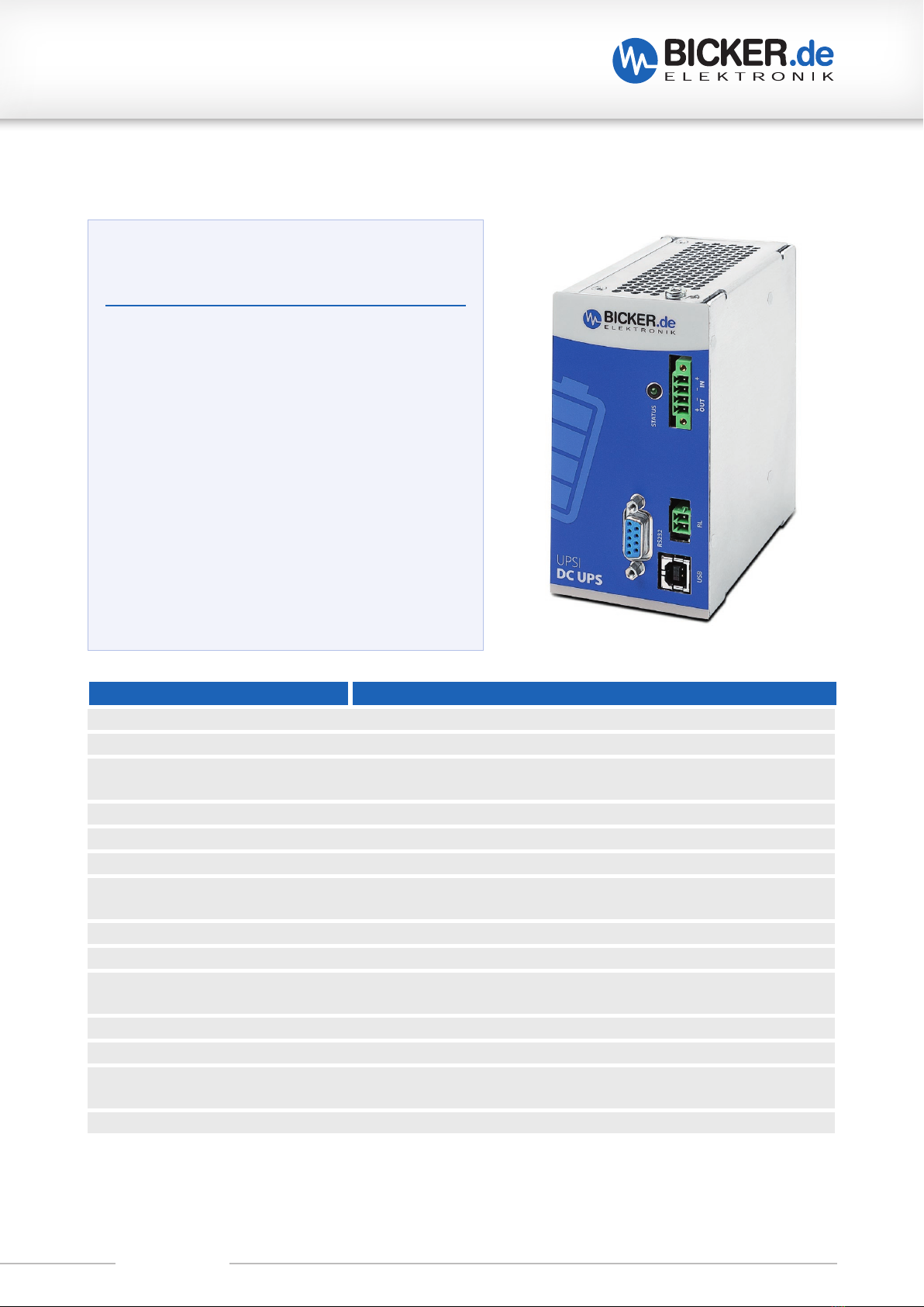
A Brief specification
12 V DC UPS (DIN rail version)
Integrated Supercaps
Up to 500 000 cycles
Capacity: 5.73 kJ
Intelligent input current detection
Regulated output voltage in battery mode
Minimum load detection
Power-fail timer function
Relay dry contact on power fail
Reboot function
Fuel gauge
Shutdown via external signal

UPSI-1208DPx
Revision 2-0 4
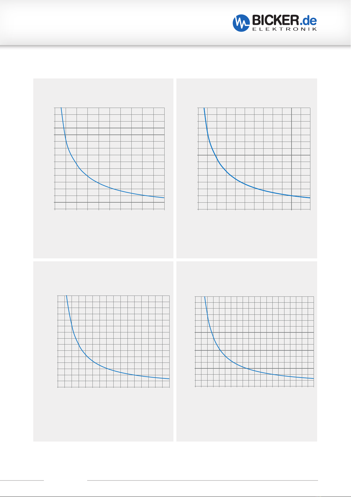
*Backup time depends on battery capacitance, load and temperature. At very high or low temperatures a reduction of backup time occurs.
Unless otherwise specified, the values apply to measurements at +25 °C
Backup time* UPSI-1208DP2 – Battery type: EDLC (Supercaps)
IOUT [A] POUT [W]
0
2
4
6
8
10
12
14
16
18
20
22
24
26
28
30
0,00,1 0,20,3 0,40,5 0,60,7 0,80,9 1,0
Backupzeit [min] UPSI-1208DP2 0...1A
Backupme[min]
IOUT[A]
0
20
40
60
80
100
120
140
160
180
200
220
240
260
280
300
0,0
1,0
2,0
3,0
4,0
5,0
6,0
7,0
8,0
Backupzeit [sec] UPSI-1208DP2 0...8A
Backupme[sec]
IOUT[A]
IOUT [A]
Backup time [min]
Backup time [sec]
POUT [W]
Backup time [min]
0
2
4
6
8
10
12
14
16
18
20
22
24
26
28
30
012345678
91
0
Backupzeit [min] UPSI-1208DP2 0...10W
Backupme[min]
POUT[W]
0
20
40
60
80
100
120
140
160
180
200
220
240
260
280
300
0
10
20
30
40
50
60
70
80
90
100
Backupzeit [sec] UPSI-1208DP2 0...100W
Backupme[sec]
POUT[W]
0
2
4
6
8
10
12
14
16
18
20
22
24
26
28
30
0,00,1 0,20,3 0,40,5 0,60,7 0,80,9 1,0
Backupzeit [min] UPSI-1208DP2 0...1A
Backupme[min]
IOUT[A]
0
20
40
60
80
100
120
140
160
180
200
220
240
260
280
300
0,0
1,0
2,0
3,0
4,0
5,0
6,0
7,0
8,0
Backupzeit [sec] UPSI-1208DP2 0...8A
Backupme[sec]
IOUT[A]
0
2
4
6
8
10
12
14
16
18
20
22
24
26
28
30
012345678910
Backupzeit [min] UPSI-1208DP2 0...10W
Backupme[min]
POUT[W]
0
20
40
60
80
100
120
140
160
180
200
220
240
260
280
300
0
10
20
30
40
50
60
70
80
90
100
Backupzeit [sec] UPSI-1208DP2 0...100W
Backupme[sec]
POUT[W]
Backup time [sec]
IOUT [A] POUT [W]

UPSI-1208DPx
Revision 2-0 5
Input voltage 12 V DC (11.5…16 V)
Input current 9 A max.
Output voltage Normal mode: VIN– 0.6 V DC max. (depending on load)
Battery mode: 12 V DC
Output current 8 A nominal
Capacitive load 3000 µF (in normal mode, at start, 0A load)
Charging method CC/ CV/CP
Protection Input: Reverse polarity protection
Output: Overcurrent protection, Short circuit protection
Interface USB, RS232, HID UPS
Battery technology LiFePO4 2.5 Ah / 25 Wh
Ambient temperature Operating Storage / Transport
-20…+50°C -30…+55°C, recommended state of charge 80%
Temperature derating See derating curve on page after next
Operating altitude ≤4000 m
Max. permitted humidity ≤95 % (at +25°C, no dew)
Dimensions W/ H / D 63 x 120 x 100 mm
(without front connectors and DIN-Rail mounting bracket)
Weight 0.6 kg
Technical Data
UPSI-1208DP3
12 V DC / 8 A
A Brief specification
12 V DC UPS (DIN rail version)
LiFePO4 battery
Up to 6 000 cycles
Capacity: 25 Wh
Intelligent input current detection
Regulated output voltage in battery mode
Minimum load detection
Power-fail timer function
Relay dry contact on power fail
Reboot function
Fuel gauge
Shutdown via external signal
UPSI-1208DPx
Revision 2-0 6
10
15
20
25
30
35
40
45
50
55
60
65
70
75
80
85
90
95
100
0
10
20
30
80
120
130
140
90
100
110
40
50
60
70
Backup time* UPSI-1208DP3 – Battery type: LiFePO4
*Backup time depends on battery capacitance, load and temperature. At very high or low temperatures a reduction of backup time occurs.
Unless otherwise specified, the values apply to measurements at +25 °C
Backupzeit [h] LFP-1025S 0...1A
Backupme[h]
IOUT[A]
0
1
2
3
4
5
6
7
8
9
10
11
12
13
14
15
0,00,1 0,20,3 0,40,5 0,60,7 0,80,9 1,0
Iout [A]
Backup time [h]
0
10
20
30
40
50
60
70
80
90
100
110
120
130
140
150
0,0
0,5
1,0
1,5
2,0
2,5
3,0
3,5
4,0
4,5
5,0
5,5
6,0
6,5
7,0
7,5
8,0
Backupzeit [min] LFP-1025S 0...8A
Backupme[min]
IOUT[A]
Iout [A]
Backup time [min]
0
10
20
30
40
50
60
70
80
90
100
110
120
130
140
150
0
5
10
15
20
25
30
35
40
45
50
55
60
65
70
75
80
85
90
95
100
Backupzeit [min] LFP-1025S 0...100W
Backupme[min]
POUT[W]
Pout [W]
Backup time [min]
Backupme[h]
POUT[W]
0
1
2
3
4
5
6
7
8
9
10
11
12
13
14
15
0123456789101112
Backupzeit [h] LFP-1025S 0...12W
Pout [W]
Backup time [h]

UPSI-1208DPx
Revision 2-0 7
Derating UPSI-1208DP3
-20…0 °C: At sub-zero temperatures, the charging time increases according to the physical properties of the cells (increased internal resistance).
0
1
2
3
4
5
-20 -10 0 10 20 30 40 50 60 70
Ambient temperature [°C]
IOUT [A]
6
7
8
Iout [A]
Ambient temperature [°C]

UPSI-1208DPx
Revision 2-0 8
A Brief specification UPSI-1208DP2 / UPSI-1208DP3 ............................................ 3
B Introduction and description ............................................................................... 9
B1 Description of the product and its functions ............................................................................................9
B2 Intended use ..............................................................................................................................................................10
B3 UPS Gen2Configuration Software ................................................................................................................10
C Safety instructions .............................................................................................. 11
D Technical Data ..................................................................................................... 12
D1 General Technical Data......................................................................................................................................... 12
D2 Drawing........................................................................................................................................................................... 20
E Name / Address / Support E-Mail / Phone number of the manufacturer ....... 20
F General Data ........................................................................................................ 21
F1 Assembly and installation advice................................................................................................................... 21
F2 Convection and installation position...........................................................................................................21
F3 Description of connectors................................................................................................................................... 23
F4 Dimensioning the upstream power supply.............................................................................................25
F5 Connecting diagram...............................................................................................................................................26
F6 Initial operation.......................................................................................................................................................... 27
F7 Overview connector / Counterpart with description / Scope of delivery............................ 27
F8 Charging time............................................................................................................................................................. 27
F9 Reverse polarity / Overcurrent / Short circuit......................................................................................... 28
F10 Backup time in battery mode........................................................................................................................... 28
F11 Behaviour in case of exceeding maximum backup time................................................................ 28
F12 Dynamic Powerboost............................................................................................................................................. 29
F13 Status LED......................................................................................................................................................................31
F14 Shutdown diagram.................................................................................................................................................. 32
F15 Recommendations for a long UPS service life.........................................................................................33
F16 Maintenance................................................................................................................................................................ 33
F17 Disposal...........................................................................................................................................................................33
F18 Disclaimer ...................................................................................................................................................................... 33
F19 Preventive measures and rules when operating the UPS system.............................................34

UPSI-1208DPx
Revision 2-0 9
B Introduction and description
Read carefully before initial operation !
This manual shall help the user to get familiar with the product and its components and features. It shall pro-
vide information as accurately and completely as possible.
The manual as well as all documents has to be read and followed strictly before installation. Otherwise in cer-
tain situations warranty and guarantee can be cancelled partly or completely. Any liability on the part of Bicker
Elektronik is excluded for possible existing errors as well as non-compliance with the instructions for use and
installation.
B1 Description of the product and its functions
The UPSI-1208DP2 and UPSI-1208DP3 (hereinafter also called UPS) are DC/DC UPS systems with numerous
digital features and high performance. The UPS combines the UPSI-1208 with an integrated energy storage:
The UPSI-1208DP2 uses an energy storage with supercap (also EDLCs) technology. The UPSI-1208DP3 uses an
energy storage with LiFePO4 technology. The primary use of the UPS is to secure the supply during power
failures and/or voltage fluctuations. The application which should be protected is connected to the output of
the UPS.
The UPS requires a rated dimensioned power supply of 12VDC at the input. After the input voltage is applied,
the UPS works in normal mode automatically. The input voltage is passed through to the output and the
integrated energy storage device is charged simultaneously. The charging current depends dynamically on
the load current at the UPS output. The green status LED lights up continuously when the UPS is in this state.
In the event of a voltage drop or a voltage fluctuation of the input voltage (below undervoltage limit),
the UPS is switched to battery mode (also backup mode). In this state, the application at the UPS output
is supplied via the energy storage device. The backup time (also buffer time) depends on the used ener-
gy storage, the value of the output current and the software settings of the UPS. An important feature
is that the output voltage in battery mode is always regulated to 12VDC and does not decrease as the
voltage of the energy storage device drops. If the UPS operates in battery mode, the status LED is slowly fla-
shing (1 Hz flashing). When the UPSI-1208DP3 (with LiFePO4 battery) is used and it is discharged completely in
battery mode, the recharging has to happen as soon as possible.
When the input voltage returns, the UPS is automatically switched back to normal mode and charging of the
energy storage device is continued.
The UPS can also be used for user-initiated shutdowns of the supply voltage or cycles. Application examples
are the replacement of larger batteries in vehicles in which the electronics should continue to be supplied, the
opening and closing of safety valves after a malfunction or the shutdown of a system
UPSI-1208DPx
Revision 2-0 10
B2 Intended use
This device is designed to be installed into a suitable enclosure which protects against electrical, water and fire
hazards and can then be used indoors and outdoors. It is primary built for being mounted on a DIN Rail and
is intended for professional use in applications such as industrial control, communication and measurement
technology. It must not be used in devices or equipment where a malfunction will cause serious injury or
endanger human life.
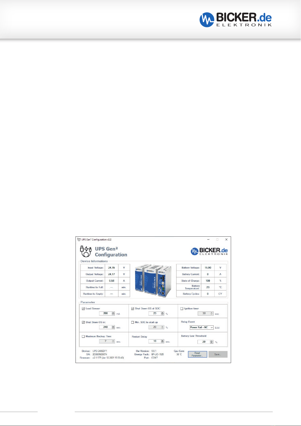
B3 UPS Gen2Configuration Software
UPS Gen Configuration Software is required for setting parameters and programming new firmware for all
UPSI Gen devices under Microsoft® Windows. The software tool also shows the operating status of the UPS
and its energy storage devices and can be connected to the device via USB:
The model has the native UPS device group integrated via USB / HID-UPS (HID Power Class). Most operating
systems (OS) recognize the UPSI models via Plug & Play without additional driver and can be used with the
operating system‘s own energy settings.
The UPS Gen2software tool offers additional setting options such as time-bound shutdown and other impor-
tant features.
The Software can be downloaded here
The User Manual for the Software can be downloaded here

UPSI-1208DPx
Revision 2-0 11
C Safety instructions
WARNING!
Disregarding of following issues can result in electric shock, fire, serious injury or death.
1. Care must be taken to ensure proper and professional wiring.
2. The device pack must not be exposed to fire and temperatures outside the specification.
3. The device must not be immersed in water or exposed to splash water.
4. The device must not be operated in a humid environment or in an environment where dew and
condensation are to be expected.
5. The device must not be opened, short-circuited, reversed, overheated or otherwise soldered/welded.
6. Changes or attempts to repair the device are to be omitted.
7. Effects of foreign objects on the device must be avoided (e.g. metal parts).
8. Do not put obviously damaged devices into operation (e.g. dents, burn marks, rough contamination).
9. Keep ventilation openings clear.
10. Device must not be dropped.
11. All parts of the device and accessories must not be eaten or swallowed.
12. A current limited source is to be used. The required current values for the UPS are described
in this manual.
13. The UPS is supplied with voltage from both the input source and the energy storage. The latter is still
energized even after the input source has been disconnected.
1. Improper use and opening of the device will void the warranty.
2. The device may only be used as intended.
3. The national accident prevention and safety regulations must be observed.
4. The assembly of the device and the electrical installation have to be state of the art.
5. The electrical, thermal and mechanical limit values have to be observed.
6. The UPS wiring specifications - as described in this manual - have to be followed.
ATTENTION!

UPSI-1208DPx
Revision 2-0 12
D Technical Data
D1 General Technical Data
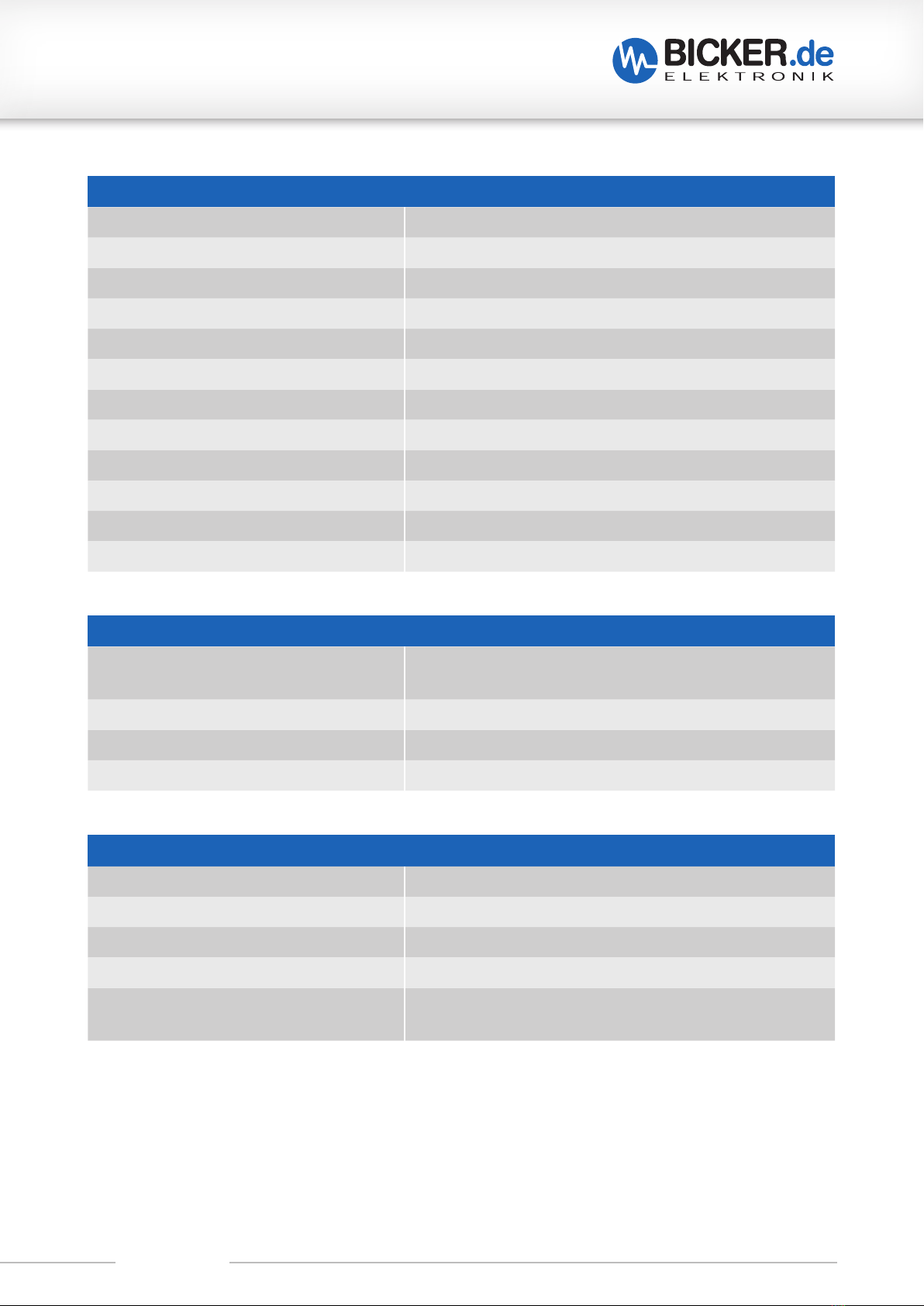
INPUT DATA
Unless otherwise stated, all specifications apply to 25°C ambient temperature,
12 V DC input voltage and nominal output current (IN).
UPSI-1208DP2 / UPSI-1208DP3
Input voltage 12 VDC
Input voltage range 11.5 VDC…16 VDC
Electric strength max. 18 VDC
Fixed connect threshold
Undervoltage
Voltage drop Input/Output
11.5 VDC
0.6 VDC max. (depending on load)
Current consumption
IN(UN, IOUT= IN, ICHARGE = 0)
IMAX (UN, IOUT = IN, ICHARGE = max)
IDYN (UN, IOUT = IDYN.BOOST, ICHARGE = 0)*
INO-LOAD (UN, IOUT = 0, ICHARGE = 0)
ICHARGE (UN, IOUT = 0, ICHARGE = max)
UPSI-1208DP2
8.1 A
9 A
8.1…10.1A
<100 mA
3.5 A
UPSI-1208DP3
8.1 A
9 A
8.1…10.1A
<100 mA
3.8 A
Power consumption
PN(UN, IOUT = IN, ICHARGE = 0)
PMAX (UN, IOUT = IN, ICHARGE = max)
IDYN (UN, IOUT = IDYN.BOOST, ICHARGE = 0)*
PCHARGE (UN, IOUT = 0, ICHARGE = max)
97 W
108 W
97…121W
42 W
97 W
108 W
97…121W
45.5 W
Internal input fuse Yes (15 A)
Switch-on time <5 s
Switch-on time battery start (BS) n. a.
*Max. 58 sec., depending on output power (see for that „F12 Dynamic Powerboost“)

UPSI-1208DPx
Revision 2-0 13
OUTPUT DATA – NORMAL MODE
Unless otherwise stated, all specifications apply to 25°C ambient temperature,
12 V DC input voltage and nominal output current (IN).
UPSI-1208DP2 / UPSI-1208DP3
Output voltage 12 VDC
Output voltage range UOUT = UIN – 0.6 VDC max. (depending on load)
Capacitive load 3000 µF (at start, 0A load)
Output current
IN
IDYN.BOOST*
ISFB
UPSI-1208DP2
8 A
8…10A
30 A (5 ms)
UPSI-1208DP3
8 A
8…10A
30 A (5 ms)
Output power
PN(UN, IOUT = IN, ICHARGE = 0)
PDYN.BOOST (UN, IOUT = IDYN.BOOST, ICHARGE = 0)*
96 W
96…120W
96 W
96…120W
Overcurrent shutdown 8…10 A for max. 58 sec*;
10…10.8A for max. 100 ms
>10.8A for max. 5 ms
8…10 A for max. 58 sec*;
10…10.8A for max. 100 ms
>10.8A for max. 5 ms
Short-circuit proof Yes
No-load proof Yes
OUTPUT DATA – BATTERY MODE
Unless otherwise stated, all specifications apply to 25°C ambient temperature,
12 V DC input voltage and nominal output current (IN).
UPSI-1208DP2 UPSI-1208DP2
Output voltage 12 VDC
Output voltage range UOUT = UIN – 0.6 VDC max. (depending on load)
Output current
IN
IDYN.BOOST*
ISFB
UPSI-1208DP2
8 A
8…10A
30 A (5 ms)
UPSI-1208DP2
8 A
8…10A
30 A (5 ms)
Output power
PN(UN, IOUT = IN, ICHARGE = 0)
PDYN.BOOST (UN, IOUT = IDYN.BOOST, ICHARGE = 0)*
91 W
91…114W
91 W
91…114W
Overcurrent shutdown 8…10 A for max. 58 sec*;
10…10.8A for max. 100 ms
>10.8A for max. 5 ms
8…10 A for max. 58 sec*;
10…10.8A for max. 100 ms
>10.8A for max. 5 ms
Short-circuit proof Yes
No-load proof Yes
Switching time normal mode
>>
battery mode <600µs
*Max. 58 sec., depending on output power (see for that „F12 Dynamic Powerboost“)

UPSI-1208DPx
Revision 2-0 14
ENERGY STORAGE UPSI-1208DP2
Charging method CC / CV / CP
Nominal voltage UN8.3 V
End-of-charge voltage 8.3 V
Battery charge current 16 A max.
Undervoltage protection 4.5 V
Battery technology EDLC (Supercap)
Nominal capacity 5.73 kJ (3.88 kJ useful) / 1.59 Wh (1.08 Wh useful)
Charging time (ICHARGE = max) App. 5 min 20 sec
Buffer time (at IOUT = 8 A) App. 33 sec
ENERGY STORAGE UPSI-1208DP3
Charging method CC / CV / CP
Nominal voltage UN9.9 V
End-of-charge voltage 10.35 V
Battery charge current ≤2C (4.5…5 A)
Undervoltage protection As soon as the first cell reaches 2.5 V
Battery technology LiFePO4
Nominal capacity 2.5 Ah / 25 Wh
Charging time (ICHARGE = max) App. 34 min
Buffer time (at IOUT = 8 A) App. 13 min

UPSI-1208DPx
Revision 2-0 15
DATA INTERFACE – USB
Interface designation USB
Numbers of interfaces 1
Connection method USB type B (female)
Locking No
Transmission physics USB 2.0
Topology Point-to-point
Protocol VCOM, HID
Transmission length ≤3 m
Access time <1 s
Chipset NXP
Electrical isolation No
CONNECTION DATA – RELAY
Connection labeling RL
Switch contact (potential free) Relay
Status (configurable) Power Fail Alarm
Switching voltage 24 VDC / 125 VAC
Current carrying capacity 1 A (DC) / 0.5 A (AC)
State - signal assignment NO (Normally Open) / NC (Normally Closed) –
configurable via Software (see UPS Gen2software manual)
Connection method Lockable plug connector
Conductor cross-section solid 0.205 mm … 1.3 mm (24 … 16 AWG)
Conductor cross-section flexible 0.205 mm … 1.3 mm (24 … 16 AWG)
Conductor cross-section with ferrule 0.205 mm … 1.3 mm (24 … 16 AWG)
Stripping length 7 mm … 9 mm
Switching time 1500 ms max.
CONNECTION DATA INPUT / OUTPUT
Connection method Screwable plug connector
Conductor cross-section solid 0.129 mm … 1.31 mm (26 … 16 AWG)
Conductor cross-section flexible 0.129 mm … 1.31 mm (26 … 16 AWG)
Conductor cross-section with ferrule 0.129 mm … 1.31 mm (26 … 16 AWG)
Stripping length 6 mm … 7 mm
Tightening torque 0.3 Nm … 0.4 Nm
UPSI-1208DPx
Revision 2-0 16
GENERAL DATA
Flammability class according to UL 94
(housing / terminal blocks)
V0
Weight 0.6 kg
UPS connection in parallel No
UPS connection in series No
HOUSING
Degree of protection IP 20
Protection class III (without PE)
Mounting type DIN-Rail mounting (EN 60715)
Housing version Aluminium
Dimension W / H / D 63 mm / 120 mm / 100 mm
(without front connectors and DIN-Rail mounting bracket)
DATA INTERFACE – RS232
Interface designation RS232
Numbers of interfaces 1
Connection method DSUB 9-Pin (female)
Locking No
Transmission physics RS232 light (TX / RX)
Topology Point-to-point
Symbol rate (baud rate) 38400
Type of cable 1:1
Transmission length ≤10 m
Access time <1 s
Voltage level -6 VDC … +6 VDC
Electrical isolation No
UPSI-1208DPx
Revision 2-0 17
ENVIRONMENTAL CONDITIONS
Ambient temperature (operation) DP2: -20… +65°C / DP3: -20… +50°C
Ambient temperature (start up without load) DP2: -30°C / DP3: -20°C
Ambient temperature
(storage / transport)
DP2: -30… +65°C / DP3: -30… +55°C
Max. permitted humidity ≤95 % (at +25°C, no dew)
Operating altitude ≤4000 m
Climate class 3k3 (EN 60721)
Degree of pollution 2
Overvoltage category
EN 61010-1
EN 61010-2-201
I
I
Indoor / Outdoor use Yes / Yes (in housing)
STANDARDS
Safety extra-low voltage IEC 61010-1 (SELV)
IEC 61010-2-201
APPROVALS
UL n.a. (possible upon consultation)
CSA
CB Scheme

UPSI-1208DPx
Revision 2-0 18
INTERFERENCE IMMUNITY ACCORDING TO EN 61000 (INDUSTRY)
Basic standard CE Fulfilled requirements according to EN 61000 (CE)
(Interference immunity of industrial environment)
Electrostatic discharge
EN 61000-4-2
Contact discharge
Air discharge
Comment
4 kV
8 kV
Criterion B
Electromagnetic HF field
EN 61000-4-3
Frequency range
Test field strength
Frequency range
Test field strength
Comment
80 MHz … 1 GHz
10 V/m
1.4 GHz … 2 GHz
3 V/m
Criterion A
Fast transients (Burst)
EN 61000-4-4
Test voltage
Comment
2 kV
Criterion A
Surge voltage load (Surge)
EN 61000-4-5
Test voltage L–N
Test voltage L–PE, N–PE
Comment
±0.5kV
±1kV
Criterion A
Power frequency magnetic field immunity
EN 61000-4-8
Test level
Comment
30A/m
Criterion A

UPSI-1208DPx
Revision 2-0 19
LEGEND
Criterion A Normal operating behaviour within the defined limits.
Criterion B Temporary impairment of the operating behaviour, that is
corrected by the device itself.
EMISSION ACCORDING TO EN 55016-2-3 (DOMESTIC)
Basic standard CE Fulfilled requirements according to EN 55016-2-3 (CE)
(Domestic)
Conducted emission from the power port
EN 55016-2-3
Frequency range
Comment
150kHz–30MHz
Conform
Electric field radiated emission
EN 55016-2-3
Frequency range
Comment
30MHz–1GHz
Conform

UPSI-1208DPx
Revision 2-0 20
D2 Drawing
E Name / Address / Support E-Mail / Phone number of the manufacturer
Bicker Elektronik GmbH · Ludwig-Auer-Straße 23 · 86609 Donauwörth · Germany
2 mm
120 mm
63 mm
8.5...9 mm
100 mm
44 mm
16.6 mm
9.7...10 mm
Unless otherwise stated,
Tolerance according to:
DIN ISO 2768 T1 - m
DIN ISO 2768 T2 - K
Table of contents
Other Bicker UPS manuals

Bicker
Bicker UPSI-2403 User manual

Bicker
Bicker IUPS-401-B8 User manual

Bicker
Bicker UPS-1000-B1 User manual

Bicker
Bicker UPSI-IP-3 Series User manual

Bicker
Bicker UPSI-1208D User manual

Bicker
Bicker UPSI-2406DP Series User manual

Bicker
Bicker UPSI-1208DP Series User manual

Bicker
Bicker IUPS-401-B1 User manual
Popular UPS manuals by other brands


Mitsubishi Electric
Mitsubishi Electric 2033D SERIES Owner technical manual

Riello UPS
Riello UPS GUARD TOWER GTT 6000 quick guide

Eaton
Eaton 9E20K-TH manual

Integra
Integra Xmart OPTIMA RT9W 6K user manual

AEG
AEG PROTECT B. 2000 operating instructions

CyberPower
CyberPower Paragon OL1500RMXL2U Specification sheet